Dissertation - FTP Directory Listing - University of Surrey
Dissertation - FTP Directory Listing - University of Surrey
Dissertation - FTP Directory Listing - University of Surrey
You also want an ePaper? Increase the reach of your titles
YUMPU automatically turns print PDFs into web optimized ePapers that Google loves.
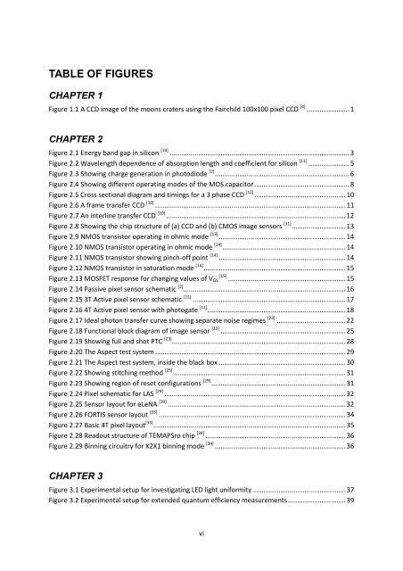
TABLE OF FIGURESCHAPTER 1Figure 1.1 A CCD image <strong>of</strong> the moons craters using the Fairchild 100x100 pixel CCD [4] ....................... 1CHAPTER 2Figure 2.1 Energy band gap in silicon [10] ................................................................................................ 3Figure 2.2 Wavelength dependence <strong>of</strong> absorption length and coefficient for silicon [11] ...................... 5Figure 2.3 Showing charge generation in photodiode [2] ........................................................................ 6Figure 2.4 Showing different operating modes <strong>of</strong> the MOS capacitor ................................................... 8Figure 2.5 Cross sectional diagram and timings for a 3 phase CCD [12] ................................................. 10Figure 2.6 A frame transfer CCD [10] ...................................................................................................... 11Figure 2.7 An interline transfer CCD [10] ................................................................................................ 12Figure 2.8 Showing the chip structure <strong>of</strong> (a) CCD and (b) CMOS image sensors [11] ............................. 13Figure 2.9 NMOS transistor operating in ohmic mode [13] .................................................................... 14Figure 2.10 NMOS transistor operating in ohmic mode [14] .................................................................. 14Figure 2.11 NMOS transistor showing pinch-<strong>of</strong>f point [14] .................................................................... 14Figure 2.12 NMOS transistor in saturation mode [14] ............................................................................ 15Figure 2.13 MOSFET response for changing values <strong>of</strong> V GS [15] ............................................................... 15Figure 2.14 Passive pixel sensor schematic [2] ....................................................................................... 16Figure 2.15 3T Active pixel sensor schematic [11] .................................................................................. 17Figure 2.16 4T Active pixel sensor with photogate [11] .......................................................................... 18Figure 2.17 Ideal photon transfer curve showing separate noise regimes [23] ..................................... 22Figure 2.18 Functional block diagram <strong>of</strong> image sensor [23] ................................................................... 25Figure 2.19 Showing full and shot PTC [23] ............................................................................................. 28Figure 2.20 The Aspect test system ...................................................................................................... 29Figure 2.21 The Aspect test system, inside the black box .................................................................... 30Figure 2.22 Showing stitching method [25] ............................................................................................ 31Figure 2.23 Showing region <strong>of</strong> reset configurations [29] ........................................................................ 31Figure 2.24 Pixel schematic for LAS [29] ................................................................................................. 32Figure 2.25 Sensor layout for eLeNA [30] ............................................................................................... 32Figure 2.26 FORTIS sensor layout [33] .................................................................................................... 34Figure 2.27 Basic 4T pixel layout [33] ....................................................................................................... 35Figure 2.28 Readout structure <strong>of</strong> TEMAPSro chip [34] ........................................................................... 36Figure 2.29 Binning circuitry for X2X1 binning mode [34] ...................................................................... 36CHAPTER 3Figure 3.1 Experimental setup for investigating LED light uniformity .................................................. 37Figure 3.2 Experimental setup for extended quantum efficiency measurements ............................... 39vi


