Overvoltages & Insulation Coordination - engineering site
Overvoltages & Insulation Coordination - engineering site
Overvoltages & Insulation Coordination - engineering site
Create successful ePaper yourself
Turn your PDF publications into a flip-book with our unique Google optimized e-Paper software.
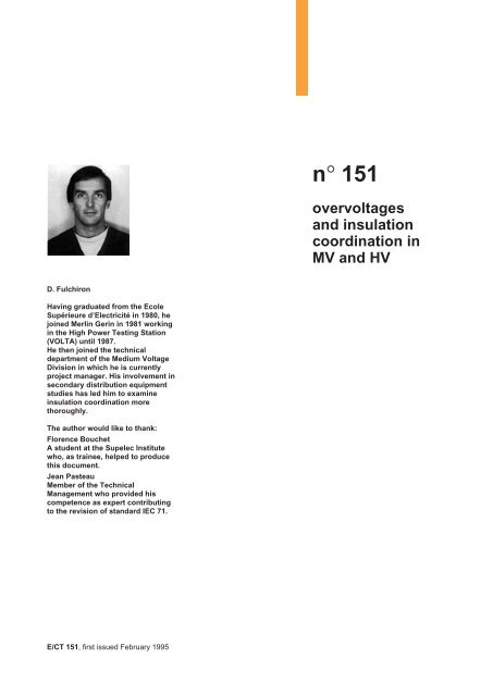
overvoltages and insulation coordinationin MV and HVcontents1. <strong>Overvoltages</strong> Power frequency overvoltages p. 4Switching overvoltages p. 5Lightning overvoltages p. 82. <strong>Insulation</strong> coordination Definition p. 11Clearance and voltage withstand p. 11Withstand voltage p. 12<strong>Insulation</strong> coordination principle p. 133. Overvoltage protective devices Dischargers p. 14Surge arresters p. 144. Standards and insulation HV insulation coordination p. 17coordination as in IEC 715. <strong>Coordination</strong> applied to Breakdown consequences p. 20electrical installation designReduction of overvoltage p. 20risks and level6. Conclusion p. 21Appendix 1: propagation of overvoltage p. 21Appendix 2: installing a surge arrester Maximum safety clearance p. 22Cabling the surge arresters p. 22Appendix 3: electricity standards p. 23Appendix 4: bibliography p. 24<strong>Insulation</strong> coordination is a disciplineaiming at achieving the best possibletechnico-economic compromise forprotection of persons and equipmentagainst overvoltages, whether causedby the network or lightning, occurringon electrical installations.It helps ensure a high degree ofavailability of electrical power.Its value is doubled by the fact that itconcerns high voltage networks. Tocontrol insulation coordination:■ the level of the possible overvoltagesoccurring on the network must beknown;■ the right protective devices must beused when necessary;■ the correct overvoltage withstandlevel must be chosen for the variousnetwork components from among theinsulating voltages satisfying theparticular constraints.The purpose of this "Cahier Technique"is to further knowledge of voltagedisturbances, how they can be limitedand the standards to ensure safe,optimised distribution of electricalpower by means of insulationcoordination. It deals mainly with MVand HV.Cahier Technique Merlin Gerin n° 151 / p.3
1. overvoltagesThese are disturbances superimposedon circuit rated voltage. They mayoccur:■ between different phases or circuits.They are said to be differential mode;■ between live conductors and theframe or earth. They are said to becommon mode.Their varied and random nature makesthem hard to characterise, allowing onlya statistical approach to their duration,amplitudes and effects. The table infigure 1 presents the maincharacteristics of these disturbances.In point of fact, the main risks aremalfunctions, destruction of theequipment and, consequently, lack ofcontinuity of service. These effects mayoccur on the installations of bothenergy distributors and users.Disturbances may result in:■ short disconnections (automaticreclosing on MV public distributionnetworks by overhead lines);■ long disconnections (intervention forchanging damaged insulators or evenreplacement of equipment).Protective devices limit these risks.Their use calls for careful drawing up ofconsistent insulation and protectionlevels. For this, prior understanding ofthe various types of overvoltages isvital: such is the purpose of thischapter.power frequencyovervoltagesThis term includes all overvoltages withfrequencies under 500 Hz.Reminder: the most common networkfrequencies are: 50, 60 and 400 Hz.Overvoltage caused by an insulationfault (see fig. 2)An overvoltage due to an insulationfault occurs on a three-phase networkwhen the neutral is unearthed orimpedance-earthed.In actual fact, when an insulation faultoccurs between a phase and the frameor earth (a damaged undergroundcable, earthing of an overheadconductor by branches, equipmentfault, ...), the phase in question isplaced at earth potential and theremaining two phases are thensubjected, with respect to earth, to thephase-to-phase voltageU = V 3.More precisely, when an insulation faultoccurs on phase A, an earth faultfactor, Sd, is defined by the ratio of thevoltage of phases B and C with respectto earth, to network phase to neutralvoltage.The following equation is used tocalculate Sd:Sd =3 (k 2 + k + 1)k + 2where k = XoXdXd is the direct reactance of thenetwork seen from the fault point, andXo the zero sequence reactance.Note that:■ if the neutral is completely unearthed,Xo =∞:Sd=3 1/ 2 = 3 ;■ if the neutral is completely earthed,Xo = Xd: Sd = 1;■ if, as in the general case,Xo ≤ 3 Xd: Sd ≤ 1.25.Overvoltage on a long off-load line(Ferranti effect)An overvoltage may occur when a longline is energised at one of its ends andnot connected at the other. This is dueovervoltage MV-HV over term steepness dampingtype voltage of frequency(cause) coefficient frontat power frequency ≤ 3 long power low(insulation fault) > 1 s frequencyswitching 2 to 4 short medium medium(short-circuit 1 ms 1 to 200 kHzdisconnection)atmospheric > 4 very short very high high(direct lightning stroke) 1 to 10 µs 1,000 kV/µsfig. 1: characteristics of the various overvoltage types.V BTTNV Aearth faultV CV BT =V CT =3 V BN3 V CNfig. 2: temporary overvoltage on an unearthed neutral network in presence of an insulationfault.CBAV ATV BTV CTthe phase-earth voltage of fault-freephase is raised to the value of thephase-to-phase voltage:Cahier Technique Merlin Gerin n° 151 / p.4
to resonance which takes the form of avoltage wave increasing in linearfashion along the line.In point of fact, where:■ L and C refer to line inductance andtotal capacity respectively;■ Us and Ue are the voltages at theopen end and at line entrance, theovervoltage factor equals:Us 1=Ue1 − L C ω 22This overvoltage factor is around 1.05for a 300 km line and 1.16 for a 500 kmline. These values are more or less thesame for HV and EHV lines.This phenomenon is particularlycommon when a long line is suddenlydischarged.Overvoltage by ferromagneticresonanceIn this case the overvoltage is the resultof a special resonance which occurswhen a circuit contains both a capacitor(voluntary or stray) and an inductancewith saturable magnetic circuit (e.g. atransformer). This resonance occursparticularly when an operation (circuitopening or closing) is performed on thenetwork with a device having poleseither separate or with nonsimultaneousoperation.The circuit shown in the diagram infigure 3, with connected in series asaturable core inductance, L, and thenetwork capacitance, C, makes iteasier to understand the phenomenon.The following three curves can then bedrawn: Uc = f(i), U L= f(i) and(U L- 1 / C ω i) = f(i);■ the first one is a straight sloping line1 / C ω;■ the second one presents a saturationbend;■ and the third one displays twooperating points (O and B) for whichvoltage at the terminals of theLC assembly is zero, and two otherstable operating points, M and P; N isan unstable point of balance.The voltages at the terminalsof L and C (point P) are high. Movefrom M to P may be due only to atransient temporarily raising voltage eto a value greater than E.These overvoltages (see the diagram infigure 3) present a risk of dielectricbreakdown and a danger for any loadsparallel-connected on C. However,more generally, the powers involvedare fairly low (1/2 C V 2 with low C) andonly likely to damage fragile equipment.It is up to the equipment designer toevaluate and limit this risk.Notes:Ferromagnetic resonance, dependingon variable L, may occur for a widefrequency band.A similar demonstration can be madefor parallel resonance.A load connected to the circuit acts asa reducing resistance and preventsmaintenance of resonance conditions.euEeOdiagramfig. 3: ferromagnetic resonance principle..LCM N Pswitching overvoltagesSudden changes in electrical networkstructure give rise to transientphenomena frequently resulting in thecreation of an overvoltage or of a highfrequency wave train of aperiodic oroscillating type with rapid damping.Normal load switching overvoltageA «normal» load is mainly resistive, i.e. itspower factor is greater than 0.7. In thiscase, breaking or making of load currentsdoes not present a major problem. Theovervoltage factor (transient voltageamplitude/operating voltage ratio) variesbetween 1.2 and 1.5.BL ω iievectorial representationUc =iC ωiC ωU = L ω i LiC ω - L ω iiCahier Technique Merlin Gerin n° 151 / p.5
<strong>Overvoltages</strong> caused by making andbreaking of small inductive currentsThis type of overvoltage is caused bythree phenomena:current pinch-off, rearcing andprearcing.The diagram in figure 4 shows anetwork supplying a load through acircuit-breaker. It contains:■ a sinusoidal voltage source with aninductance, L 1and a capacitance, C 1,■ a circuit-breaker, D, which cannot bedissociated from its stray elements,Lp 1and Cp 1,■ an inductive load, L 2, the distributedcapacitance of which cannot beoverlooked, symbolised by acapacitor, C 2,■ finally, a line inductance, L 0,generally negligible.■ current pinch-offThe arc occurring on breaking of lowcurrents, in particular less than circuitbreakerrated current, takes up littlespace. It undergoes considerablecooling due to the circuit-breaker’scapacity to break far higher currents.It thus becomes unstable and itsvoltage may present high relativevariations, whereas its absolute valueremains far below network voltage(case of breaking in SF6 or vacuum).These e.m.f. variations may generateoscillating currents (see fig. 4) of highfrequency in the adjacent capacitances,both stray and voluntary. The amplitudeof these currents can become nonnegligiblewith a 50 Hz current andreach 10 % of its value.Superimposition of the 50 Hz currentand of this high frequency current in thecircuit-breaker will result in the currentmoving to zero several times aroundthe zero of the fundamental wave(see fig. 5).The circuit-breaker, little affected bythese low currents, is often capable ofbreaking at the first current zerooccurring. At this moment, the currentsin the generator and load circuits arenot zero. The instantaneous value, i, ofthe 50 Hz wave on arc extinguishing isknown as the «pinched-off current».The energy trapped in the circuit variesaccording to the type of impedancesinvolved, mainly resistive and inductive.Small inductive currents (see fig. 4)present a load with a high inductancewhich, when the arc is extinguished,will have an energy given by:12 L 2 I2 .The L 2C 2circuit is now in the slightlydamped, free oscillation state, and thepeak value V of the voltage occurringat the terminals of C 2is approximatedby the energy conservationhypothesis:12 L 2 I2 = 1 2 C 2 V2 .If C 2is only made up of straycapacitances with respect to frames,the value of V may present a risk forequipment insulation (circuit-breaker orload).The generator circuit has an equivalentbehaviour, but its inductance isgenerally much smaller and thevoltages occurring at the terminals ofC 1are thus far lower.■ rearcingThis occurs when the pinching-offphenomenon described above causesan input-output overvoltage to occur atthe terminals of the circuit-breakerunable to be withstood by the latter: anarc then occurs. This simplifiedexplanation is complicated by thefirst parallel oscillation loopL 1DC 1 C 2 L 2L 0second oscillationloopCp 1Lp 1fig. 4: equivalent circuit for the study of overvoltages caused by inductive current breakingwhere:Cp 1 : circuit-breaker capacitance,Lp 1 : circuit-breaker inductance."pinched-off"currentpossibleextinguishingcurrent incircuit-breaker50 Hz wavefig. 5: superimposition of a high frequency oscillating current on a power frequency current.Cahier Technique Merlin Gerin n° 151 / p.6
presence of the stray elementspresented above.In actual fact, following current breakingand rearcing, three oscillatingphenomena occur simultaneously atthe respective frequencies Fp 1,Fp 2andFm:■ in the loopD - Lp 1- Cp 1:1Fp 1=2 π Lp 1Cp 1of around a few MHz.■ in the loopD - C 1- Lo - C 2:Fp 2 =12πC 1 + C 2Lo C 1 C 2of around 100 to 500 kHz.■ throughout the circuit,Fm =12πL 1 + L 2L 1 L 2 5 (C 1 + C 2 )of around 5 to 20 kHz.Multiple rearcing then occurs(chopping) until it is stopped byincreasing contact clearance. Thisrearcing is characterised by highfrequency wave trains of increasingamplitude. These overvoltage trainsupstream and downstream from thecircuit-breaker can thus present aconsiderable risk for equipmentcontaining windings.This phenomenon must not beconfused with «reignition» which is thereappearance of a power frequencycurrent wave and thus a breakingfailure on the current wave zero.■ prearcingWhen a device closes (switch,contactor or circuit-breaker), there is amoment when dielectric withstandbetween contacts is less than appliedvoltage. In the case of rapidly closingdevices, with respect to 50 Hz,behaviour depends on the phase angleduring operation.An arc is then created between thecontacts, and the circuit witnesses avoltage pulse due to the suddencancellation of voltage at the deviceterminals. This pulse may result inoscillation of existing parallel circuits(surging discharge of straycapacitances) and reflections onimpedance failures, and hence in theappearance of high frequency currents,with respect to 50 Hz, through the arc.If device operation is slow comparedwith this phenomenon, the arcingcurrent may be made to move throughzero by superimposition of the highfrequency current and the incipient50 Hz current.Extinguishing of the arc, according toequipment characteristics, will thenresult in a behaviour similar to thatdescribed for the phenomena above.However, since dielectric withstandbetween contacts decreases withclosing, the successive overvoltagesdecrease right up to complete closing.This phenomenon is extremelycomplex. The resulting overvoltagesdepend, among other factors, on:■ circuit-breaker characteristics(dielectric properties, capacity to breakhigh frequency currents, ...),■ characteristic cable impedance,■ load circuit natural frequencies.<strong>Overvoltages</strong>, extremely hard tocalculate, cannot generally bepredetermined since they involveuncalculable elements which vary from<strong>site</strong> to <strong>site</strong>. They also require asophisticated mathematical model ofthe arc chute.Prearcing overvoltages particularlyaffect, in HV and MV, off-loadtransformers on energising and motorson starting (see Merlin Gerin "CahierTechnique" n° 143).Overvoltage caused by switching oncapacitive circuitsCapacitive circuits are defined ascircuits made up of capacitor banks,and off-load lines.■ energising of capacitor banksWhen capacitor banks are energised,normally without initial load, and in thecase of slow operating devices, arcingoccurs between the contacts aroundthe 50 Hz wave peak.Damped oscillation of the LC system infigure 6 then occurs. The frequency ofthis oscillation is generally far higherthan power frequency, and voltageoscillation is mainly centered aroundthe 50 Hz wave peak value. Themaximum voltage value observed isthen around twice the 50 Hz wave peakvalue.In the case of faster operating devices,arcing does not systematically occuraround the peak value: the overvoltage,if any, is thus lower.If a capacitor bank is put back intooperation very soon after it has beendisconnected from the network, itsresidual load voltage is between zeroand the 50 Hz wave peak voltage.Arcing between contacts occurs arounda peak of oppo<strong>site</strong> polarity (breakdownunder a stress twice peak voltage).The oscillation described above occurswith a double initial pulse. Themaximum voltage value observed maythen be close to three times the 50 Hzpeak voltage.For safety reasons, capacitor banks arealways fitted with discharging resistorsable to eliminate residual voltages withtime constants of around one minute.Consequently, an overvoltage factorof 3 corresponds to very specific cases.■ energising of off-load lines or cablesSlow closing of a device on this type ofload causes, in this case also, arcingaround the 50 Hz peak: the voltagestep applied to one end of the line orcable will spread and be reflected onthe open end (see appendix 1).Superimposition of the incident stepand the reflected step results in avoltage stress twice the applied step,give or take the dampings, andassuming that the 50 Hz can be likenedto DC for these phenomena.eLfig. 6: schematic diagram showing acapacitor operating circuit.CCahier Technique Merlin Gerin n° 151 / p.7
As this type of behaviour is related tothe distributed inductances andcapacitances of the conductorsconsidered, overhead lines present, inaddition, a phase-to-phase couplingmaking modelling relatively complex.This reflection phenomenon must betaken into consideration particularly in(EHV) transmission lines, as a result ofthe small relative difference betweenoperating voltage and insulatingvoltage.■ capacitive circuit breakingBreaking of capacitive circuits normallypresents few difficulties. In point of fact,as capacitances remain charged at the50 Hz wave peak value, after the arc isextinguished at current zero, voltage isresumed at the equipment terminals at50 Hz with no transients. However, onealternation after breaking, the device issubjected to an input output voltagetwice peak voltage.If it is unable to withstand this stress(e.g. opening not yet sufficient),reignition may occur. This is followed,provided the circuit so allows (singlephaseor connected neutral circuit) byvoltage inversion at capacitor terminals,raising them to a maximum load ofthree times peak voltage (see fig. 7).The current breaks yet again and anew reignition may take place with avalue five times peak voltage at thenext alternation.Such behaviour may result inconsiderable escalation and must beavoided by choosing equipment whichprevents reignition.Note that the rising front of lightningstrokes chosen by standards is 1.2 µsfor voltage and 8 µs for current.A distinction is often made between:■ «direct» lightning strokes striking aline;■ «indirect» lightning strokes, fallingnext to a line, on a pylon or, whichcomes to the same, on the earth cable(this cable, earthed, connects the topsof pylons and protects live conductorsfrom direct lightning strokes).Direct lightning strokesThis results in the injection of a currentwave of several dozens of kA in the line.This current wave, which may causeconductors to melt by propa-gating oneither side of the point of impact (seefig. 9) results in an increase in voltage Ugiven by the formula:U = Zc i 2where i is the injected current andZc the characteristic line zero sequenceimpedance (300 to 1,000 ohms).U then reaches values of severalmillion volts, which no line canwithstand. At a point in the line, forexample at the first pylon the wavemeets, voltage increases untilclearance breakdown occurs (insulatorstring). According to whether or notarcing has occurred (depending on thevalue of the current injected into theline), the wave which continues topropagate after the pylon is said to bebroken or full.For various network voltages, arcingdoes not occur below the critical currentindicated by the straight line in figure 10.For networks with a voltage less than400 kV, virtually all direct lightningstrokes result in arcing and an earthfault.In actual fact, it is estimated that only3 % of overvoltages, observed on theFrench 20 kV MV public network,exceed 70 kV and are thus ascribableto direct lightning strokes. Moreover, asa result of attenuation of the voltage+5 Vclightning overvoltagesA storm is a natural phenomenon wellknown to all, and which is bothspectacular and dangerous.On average 1,000 storms break outeach day throughout the world.In France, (see fig. 8), they cause eachyear 10 % of fires, the death of40 people and 20,000 animals and50,000 electricity or phone cuts.Overhead networks are those mostaffected by lightning overvoltages andovercurrents.Lightning strokes are characterised bytheir polarisation: they are generallynegative (negative cloud and positiveground). Roughly 10 % have reversedpolarity, but these are the most violent.VI20 m sbreakingVc1/2 T-3 Vcfig. 7: voltage escalation on separation of a capacitor bank from the network by a slowoperating device.U, ItCahier Technique Merlin Gerin n° 151 / p.8
55105105101525102510151015253020202515303030252525wave throughout its propagation alongthe line, maximum overvoltages (veryrare) at the entrance of a substation orbuilding are estimated at 150 kVin MV.It should be remembered that thehighest impulse withstand of 24 kVequipment is 125 kV.Indirect lightning strokesWhen indirect strokes fall on a supportor even simply next to a line, highovervoltages are generated in thenetwork.Indirect strokes, more frequent thandirect ones, may prove almost asdangerous.■ if lightning falls on the pylon or theearth cable, the current flowing offcauses an increase in metal framepotential with respect to earth(see fig. 11). The correspondingovervoltage U may reach severalhundreds of kV.U = Ri2 + L 2didtwhere R is the earth connection steepwave resistance and L is theinductance of the pylon and/or theearthing conductor.5 10 15 20 25 30 daysfig. 8: isokeraunic levels in continental France (graduated in annual mean number of stormydays).Source: Météorologie Nationale.U = Ri2 + L 2didtiU = Zc i/2Ui/2ilikelihood (%)99.5225 kV989590400 kVLUi/2i/27050750 kV1,100 kVfig. 9: when lightning strikes directly, thecurrent wave propagates on either side ofthe point of impact.301,500 kV103 5 10 20 30 50lightning stroke strenght (kA)fig. 10: statistical distribution of the strengthof direct lightning stokes and minimumarcing strengths as a function of networkvoltage level.Rfig. 11: when lightning falls on the earthcable, current evacuation causes anincrease in the potential of the pylon metalframe with respect to earth.Cahier Technique Merlin Gerin n° 151 / p.9
When this voltage reaches the arcingvoltage of an insulator, an «arcingreturn» occurs between the metalstructure and one or more of the liveconductors.In the case of network voltages greaterthan 150 kV, this arcing return isunlikely. The quality of pylon earthconnections plays an important role.From 750 kV onwards, there is virtuallyno more risk of arcing return, thusjustifying the installation of earth cableson EHV lines. Below 90 kV, thesecables only provide efficient protectionif the pylon earth connection isexcellent.■ if lightning falls next to the line, theenergy flowing off to the ground causesa very fast variation of theelectromagnetic field. The wavesinduced on the line are similar in shapeand amplitude to those obtained bydirect lightning. They are mainlycharacterised by their very steep front(around one micro-second) and theirvery fast damping (whether or notaperiodic) (typical characteristics ofthese waves as in standard IEC 60:front time: 1.2 µs and tail time: ≈ 50 µs).■ when the voltage wave resulting froma lightning stroke passes through aMV / LV transformer, transmissionmainly occurs by capacitive coupling.The amplitude of the overvoltage thustransmitted, observed on the secondarywinding on the LV side, is less than10 % of its value on the MV side(generally less than 70 kV). Therefore,on LV lines, induced overvoltages aregenerally less than 7 kV.A statistical observation, retained bythe French electrotechnical committee,revealed that 91 % of overvoltagesoccurring at LV consumers did notexceed 4 kV and 98 % did not exceed6 kV (see fig. 12). This accounts, forexample, for the connection circuitbreakermanufacturing standard whichstipulates an impulse withstand of 8 kV.Electrostatic overvoltagesOther types of atmospheric dischargesexist. Indeed, although the majority ofinduced overvoltages areelectromagnetic in origin, some areelectrostatic and concern in particularunearthed networks.30252015105number ofovervoltages-12-10 -8 -6 -4 -2 0 2 4 6 8 10 kVatmospheric overvoltagelevelsfig. 12: statistical distribution of atmosphericovervoltage amplitude drawn up from twoobservation campaigns (183 between 1973and 1974, and 150 in 1975), henceduplication of curves.For example, in the minutes precedinga lightning stroke, when a cloudcharged at a certain potential is placedabove a line, this line takes on acharge of oppo<strong>site</strong> direction (seediagram in figure 13).Before the lightning strikes, thusdischarging the cloud, an electric field,E, thus exists between the line and theground which can reach 30 kV/m.Under the effect of this field, the line/earth capacitor is charged to a potentialof around 150 to 500 kV according tohow high the line is from the ground.Unenergetic breakdown may thenoccur in the least well insulatedcomponents of the network.When arcing occurs between the cloudand the earth, since the electric fieldhas disappeared, the capacitancesdischarge.++-E+ +- -+ +fig. 13: origin of an electrostatic overvoltage.Cahier Technique Merlin Gerin n° 151 / p.10
2. insulation coordinationThe first electrical networks (Grenoble-Jarrie 1883) were technologicallyextremely rudimentary and at the mercyof atmospheric conditions such as windand rain:■ wind, by causing inter-conductorclearance gaps to vary, wasresponsible for arcing;■ rain encouraged current leaks toearth.These problems resulted in:■ use of insulators;■ determination of clearances;■ earthing of metal frames of devices.definitionThe purpose of insulation coordinationis to determine the necessary andsufficient insulation characteristics ofthe various network components inorder to obtain uniform withstand tonormal voltages and to overvoltages ofvarious origins (see fig. 14). Its finalobjective is to ensure safe, optimiseddistribution of electrical power.By «optimised» is meant finding thebest possible economic balancebetween the various parametersdepending on this coordination:■ cost of insulation;■ cost of protective devices;■ cost of failures (operating loss andrepairs) in view of their probability.The first step towards removing thedetrimental effects of overvoltages is toconfront the phenomena generatingthem: a task which is not alwayssimple. Indeed, although equipmentswitching overvoltages can be limitedby means of suitable techniques, it isimpossible to have any effect onlightning.It is thus necessary to locate the pointof least withstand through which thecurrent generated by the overvoltagewill flow, and to equip all the othernetwork elements with a higher level ofdielectric withstand.Before presenting the various technicalsolutions (methods and equipment), areminder will be given of the definitionsof clearance and withstand voltage.overvoltagefactor> 442 to 4≤ 31overvoltagetypeslightningelectrostaticswitchingpower frequencyfig. 14: various voltage levels present onMV-HV networks.creepagedistanceair clearancefig. 15: air clearance and creepage distance.clearance and voltagewithstandClearanceThis term covers two notions: «gasclearance (air, SF6, etc...) and«creepage distance» of solid insulators(see fig. 15):■ gas clearance is the shortest pathbetween two conductive parts;■ creepage distance is also theshortest path between two conductors,but following the outer surface of a solidinsulator (this is known as creepage).These two clearances are directlyrelated to the concern with overvoltageprotection, but do not have identicalwithstand.Voltage withstandThis varies in particular according tothe type of overvoltage applied(voltage level, rising front, frequency,time....).Moreover, creepage distances may besubjected to ageing phenomena,specific to the insulating material inquestion, causing deterioration of theircharacteristics.airclearanceCahier Technique Merlin Gerin n° 151 / p.11
The main influencing factors are:■ environmental conditions (humidity,pollution, UV radiation);■ permanent electrical stresses (localvalue of electric field).Gas clearance withstand also dependson pressure:■ variation of air pressure with altitude;■ variation of device filling pressure.withstand voltageIn gases, insulation withstand voltage isa highly nonlinear function of clearance.For example, in air, a root mean squarevoltage stress of 300 kV/m isacceptable under 1 m, but can bereduced to 200 kV/m between 1 and4 m and to 150 kV/m between 4 and8 m. It should also be pointed out thatthis clearance is practically unaffectedby rain.This macroscopic behaviour is due tothe lack of uniformity of the electric fieldbetween electrodes of all shapes andnot to intrinsic gas characteristics. Itwould not be observed between flatelectrodes of «infinite» size (uniformfield).Creepage distances of busbarsupports, transformer bushings andinsulator strings are determined toobtain a withstand similar to direct airclearance between two end electrodeswhen they are dry and clean. On theother hand, rain and especially wetpollution considerably reduce theirwithstand voltage.Power frequency withstandIn normal operating conditions, networkvoltage may present short durationpower frequency overvoltages (afraction of a second to a few hours:depending on network protection andoperating mode). Voltage withstandchecked by the standard one-minutedielectric tests is normally sufficient.Determination of this category ofcharacteristics is simple, and thevarious insulators are easy to compare.For example, figure 16 provides acomparison of voltage withstandsbetween air and SF6 as a function ofpressure.Switching impulse voltage withstandClearances subjected to switchingimpulses have the four following mainproperties:■ nonlinearity, mentioned above, in theclearance/voltage relationship;■ dispersion, which means withstandmust be expressed in statistical terms;■ unbalance (withstand variesaccording to whether wave polarity ispositive or negative);■ passage through a minimum curvevalue of the withstand voltage as afunction of front time. When the gapbetween electrodes increases, thisminimum value moves to increasinglyhigher front times (see fig. 17). Onaverage it is around 250 µs whichaccounts for the choice of standard testvoltage rising front (standard tests as inIEC 60: application of a wave of fronttime 250 µs and half-amplitude time2,500 µs).Lightning overvoltage withstandIn the case of lightning, withstand ischaracterised by far greater linearitythan for the other stress types.Dispersion is present in this case alsowith a positive polarity withstand (the«+» applied to the most pointedelectrode) inferior to that of negativepolarity.The two following simple formulasenable withstand to a 1.2 µs/50 µspositive polarity impulse of an air gap tobe evaluated for EHV and MV networks:d■ U 50 =1. 9U 50= voltage for which breakdownlikelihood is 50 %;d■ Uo =2.1Uo = withstand voltagewhere d is clearance in metresU 50and Uo are in MV.A large number of experimental studieshave made it possible to draw upprecise correspondence tables betweenclearance and withstand voltage,taking into account a variety of factorssuch as front and tail times,environmental pollution and insulatortype.To give an example, figure 18 showsthe variations in voltage U 50as afunction of clearance and tail time T 2fora positive peak-plane interval.Moreover, table T in figure 19 showsthat withstand voltage does not dependon rising front time.10080604020fig. 16: SF6 and air breakdown voltage as afunction of absolute pressure.432101 2 3 4 5 6 7absolute pressure (bar)withstand voltage U 50 (MV)01 10 100 1,000locus of minimums13 m7 m4 m2 m1 mfronttime (µs)fig. 17: line showing minimum withstandvalues as a function of front time of impulseapplied in positive polarity.U 50kV4,0003,0002,000breakdownvoltage(peak kV)d = 8 m6 m4 m2 mmSF6air50Hz1,00010 100 1,000 T2 µs.fig. 18: U 50as a function of time T 2decreasing at half-amplitude.Intervale between the positive peak and theplane: d = 4 - 6 - 8 m.Cahier Technique Merlin Gerin n° 151 / p.12
T cr 7 22(µs)T 2 1,400 1,500(µs)U 50 2,304 2,227(kv)σ 370 217fig. 19: influences of time up to the peak ondielectric withstand of a positive peak-planeinterval = d = 8 m.insulation coordinationprincipleStudy of insulation coordination of anelectrical installation is thus thedefinition, based on the possiblevoltage and overvoltage levels on thisinstallation, of one or more overvoltageprotection levels. Installation equipmentand protective devices are thus chosenaccordingly (see fig. 20).Protection level is determined by thefollowing conditions:■ installation;overvoltagefactor> 442 to 4≤ 31overvoltage typesatmosphericelectrostaticswitchingpower frequencyprotection leveldischargerssurge arrestersovervoltagesclearedwithstand levelMV equipmentinsulationvoltagewithstoodfig. 20: insulation coordination: correctly protection level and equipment withstand as a functionof probable overvoltages.■ environment;■ equipment use.Study of these «conditions» determinesthe overvoltage level to which theequipment could be subjected duringuse. Choice of the right insulation levelwill ensure that, at least as far as powerfrequency and switching impulses areconcerned, this level will never beovershot.As regards lightning, a compromisemust generally be found betweeninsulation level, protection level ofarresters, if any, and acceptable failurerisk.Proper control of the protection levelsprovided by surge limiters requiresthorough knowledge of theircharacteristics and behaviour: this isthe purpose of the following chapter.Cahier Technique Merlin Gerin n° 151 / p.13
3. overvoltage protective devicesDischargers and surge arresters arethe devices used to clip and limit highamplitude transient overvoltages. Theyare normally designed so that they candeal with lightning overvoltages.dischargersUsed in MV and HV, they are placed inparticularly exposed network points andat the entrance to MV/LV substations.Their function is to create a weak pointcontrolled in network insulation so thatany arcing will systematically occur justthere.The first and oldest protective device isthe point discharger. It consisted of twopoints facing each other, known aselectrodes, one connected to theconductor to be protected and the otherto the earth.The most common current models usethe same principle but contain two«horns» to elongate the arc, simplifyrestoration of dielectric qualities bydeionising the arcing gap and, incertain cases, to extinguish the arc.In addition, some models are fitted witha rod, between these two electrodes,designed to prevent untimely «shortcircuiting»by birds (see fig. 21) andtheir electrocution.The gap between the two electrodesenables adjustment of protection level.Although this device is simple, fairlyefficient and economical, it has manydrawbacks:■ arcing voltage is considerablydispersed and depends to a largeextent on atmospheric conditions:variations of more than 40 % havebeen observed;■ arcing level also depends onovervoltage amplitude (see fig. 22);■ arcing delay increases as overvoltagedecreases.In these conditions, an impulse voltagemay cause arcing of a device with awithstand voltage greater than that ofthe discharger, for the simple reasonthat this device has a smaller arcingdelay (e.g. cables).earth electrodeelectrodeholderrigid anchoringchaindevice for adjusting B andlocking the electrodebirdproof rod45° 45°Bphase electrodefig. 21: a MV discharger with birdproof rode.g.on EDF 24 kV networks, B ≈ 25 mm.kv90080070060050040030020010000.5 1 1.5 2 2.5 3 3.5 4ØMoreover, after arcing, ionisationbetween the electrodes maintains thearc which is then supplied by networkvoltage and may give rise (accordingto neutral earthing) to a powerfrequency retaining current. Thiscurrent is a full earth fault and requiresintervention of the protective devicesplaced at the front of the line (e.g.rapid reclosing circuit-breaker or shuntcircuit-breaker).Finally, arcing causes the appearanceof a steep front broken wave whichcould damage the windings (transformersand motors) placed nearby.Although still used in networks,dischargers are today increasinglyreplaced by surge arresters.surge arrestersArresters have the advantage of havingno retaining current and of preventingpoint discharger e = 350 mmtests performed in 1.2 / 50 wavearcing pointstheoretical voltage curve line:beforearcingafterarcingvoltage/time characteristicfig. 22: behaviour of a point discharger in standard lightning impulse, as a function of peakvalue.µsCahier Technique Merlin Gerin n° 151 / p.14
the network from being short-circuitedand then de-energised after arcing.A variety of models have beendesigned: water stream arrester, gasarrester… Only the most common typesare presented in the paragraphs below.These arresters are used on HV andMV networks.Nonlinear resistance arresters andair gap protectorsThis arrester type connects in series airgap protectors and nonlinearresistances (varistors) able to limitcurrent on occurrence of a surge.Once the discharging current wave hasflown off, the arrester is only subjectedto network voltage. This voltagemaintains an arc on the air gapprotector, but the correspondingcurrent, known as the «retainingcurrent» flows through the resistancewhose value is now high. It is thussufficiently low not to damage the airgap protector and to be cleared whenthe current moves to zero for the firsttime (the arc is naturally extinguished).Nonlinearity of resistances maintains aresidual voltage which appears at theterminals of the device, close to arcinglevel, since resistance decreases ascurrent increases.A variety of techniques have beenused to produce varistor arresters andair gap protectors. The most classicalkind uses a silicon carbide (SiC)resistance.Some arresters also contain voltagedistribution systems (resistive orcapacitive dividers) and arc blowingsystems (magnets or coils for magneticblowing).This type of arrester is characterisedby:■ its extinction voltage or ratedvoltage, which is the highest powerfrequency voltage under which thearrester can be spontaneously deenergised.It must be greater than thehighest short duration power frequencyovervoltage which could occur on thenetwork;■ its arcing voltages according to waveshape (power frequency, switchingimpulse, lightning impulse....); they arestatistically defined;■ its impulse current evacuationcapacity, i.e. its energy dissipationcapacity. Absorption capacity isgenerally given by withstand torectangular current waves.Zinc oxide (ZnO) arrestersMade up only of varistors, they areincreasingly replacing nonlinearresistance arresters and air gapprotectors (see fig. 23).connecting spindleexhaust pipe andoverpressure devicein the upper andlower flangesfault indicationplateexhaust pipeflangering clampingdeviceAbsence of air gap means that ZnOarresters are permanently conductive,but under protected network ratedvoltage, have a very small earthleakage current (less than 10 mA).Their operating principle is very simple,based on the highly nonlinearcharacteristic of ZnO varistors.This nonlinearity is such that resistancedecreases from 1.5 M Ω to 15 Ωflange(aluminium alloy)elastic stirrupfig. 23: example of the structure of a ZnO arrester in a porcelain enclosure for the EDF 20 kVnetwork.rivetZnO blockswasherspacerthermal shieldporcelain enclosurecompression springrubber sealprestressed tightnessdeviceoverpressure deviceCahier Technique Merlin Gerin n° 151 / p.15
etween operating voltage and voltageat rated discharging current(see fig. 24).The advantage of these arresters istheir increased limitation and reliabilitycompared with silicon carbide arresters.Improvements have been made inrecent years, in particular in the thermaland electrical stability field of ZnOpellets on ageing.Thus in 1989 only two failures wereobserved on 15,000 surge arresters ofthis type installed by EDF after eighteenmonths’ experimentation. No changeswere noted in the characteristics,checked by tests.ZnO arrresters are characterised by(see fig. 25):■ their maximum permanent operatingvoltage;■ their rated voltage which may be linked,by analogy with silicon carbide arresters,to withstand to temporary overvoltages;peak kVU600500400300200100ZnO■ the protection level, defined arbitrarilyas the residual voltage of the arrestersubjected to a given current impulse(5, 10 or 20 kA according to class),8/20 µs wave;■ rated discharging current;■ impulse current withstand.(this refers to the need for withstand tolong waves causing considerableenergy dissipation and not to the needto flow off such currents in operation).EnclosureZinc oxide arresters are available:■ in porcelain enclosures for nearly alloperating voltages;■ in synthetic enclosures (glass fibreplus resin) for distribution networks.The second technique, more recent,has produced arresters which are farlighter, less vulnerable to vandalismand with better live part protectionagainst humidity since they arecompletely compound-filled. In point ofSiClinearfact, humidity is the main cause offailure identified on the ZnO arresters.The outside of these arresters isgenerally made up of silicon polymerproviding environmental resistance andreconstitution of sufficient creepagedistances. Their internal compositionand silicon enclosures mean that thesearresters can be placed in far morepositions with optimisation of implementation(e.g.: horizontal mounting).In addition to EDF specifications suchas HN 65S20 / IEC 99-1, a variety ofFrench standards apply to arresters,e.g. the NF C 65-100 for HV installationdevices.In conclusion, these various arrestertypes are used for protection ofequipment, transformers and cables. Inthis case, practically all the arrestersused are zinc oxide ones which aregradually replacing horn gaps andsilicon carbide arresters.The purpose of this evolution isincreased accuracy of protection levelsto guarantee insulation coordination toa even higher degree.Readers interested in implementationof arresters can refer to appendix 2.■ maximum permanent 12.7 kVvoltage■ rated voltage24 kV■ residual voltage at rateddischarging current< 75 kV■ rated discharging current(8/20 µs wave) 5 kA■ impulse current withstand(4/10 µs wave) 65 kA.001 .01 .1 1 10 100 1,000 10,000 Ifig. 24: characteristics of two arresters with the same level of protection 550 kV/10 kA peak kV.fig. 25: example of characteristics of a ZnOarrester meeting specification EDFHN 65S20.Cahier Technique Merlin Gerin n° 151 / p.16
4. standards and insulation coordinationFor many years now the InternationalElectrotechnical Commission (IEC) hasbeen concerned with the problem ofHV insulation coordination.<strong>Insulation</strong> coordination is dealt with intwo main documents:■ IEC 664 for LV;■ IEC 71 for HV.IEC 71 is divided into two parts, thesecond part forming an exhaustiveapplication guide.«Product» standards, including:■ IEC 694 «common clauses forequipment»;■ IEC 76 «transformers»;■ IEC 99 «surge arresters»;comply with IEC 71 as regards specificwithstand voltages.HV insulation coordinationas in IEC 71One of the objectives of this standardwhich should come into force in 93 is toexplain and break down the variousfactors for achievement of withstandvoltages. This approach encouragessearch for optimisation and evenreduction in voltage withstand levels.Standard IEC 71 proposes conventionalmodelling of actual stresses by waveshapes producible in laboratories andhaving shown satisfactory equivalence.Moreover, two new concepts are dealtwith in this standard:■ longitudinal insulation (between theterminals of the same phase of an opendevice);■ consideration of altitude and ofinstallation ageing.This draft-standard distinguishesinternal insulation, external insulationand two voltage ranges:■ internal insulation covers everythingnot in ambient air (for example, liquidinsulation for transformers, SF6 orvacuum for circuit-breakers);■ external insulation refers to airclearances.■ range l: from 1 kV to 245 kV inclusive■ range ll: above 245 kV.For each of these, implementation ofinsulation coordination varies slightly.A table of standardised rated withstandvoltages exists for each range. Thesetables have been drawn up accordingto various criteria, and, although mostlyempirical up to now, have beenconfirmed, with a few reservations, byexperience. Indeed, it cannot be deniedthat the levels laid down, which havenot been changed for years, are fullyacceptable as regards operating safety.Moreover, the gradual replacement ofdischargers by arresters enablesreduction of the safety margin whichhad become superfluous betweenarrester protection level and equipmentspecified insulating voltage.Determining insulation levelsThe standard does not stipulateinvariable withstand voltages valid in allcases, but enables insulationcoordination studies to be carried out ina number of stages:■ definition of relationships betweennetwork type and choice of itsinsulations.The purpose is to establish thecharacteristics of the maximumpossible permanent voltages and theforeseeable temporary overvoltages asa function of:■ network structure and its ratedvoltage,■ the neutral earthing connectiondiagram,■ the substations and rotatingmachines present on the line,■ the type and position of surgelimitation devices, if any,and according to considerationscommon to all overvoltage classesdefined by the standard (see fig. 26).overvoltage low frequency transientclass permanent temporary slow front fast front very fast frontshapeT tT T p T t T 1Tf2T 2Tt100 > T f > 3 nsshape range f = 50 or 60 Hz 10 < f < 500 Hz 5,000 > T p > 20 µs 20 > T 1 > 0.1 µs 0.3 > f 1 > 100 MHz(frequency, rising front,30 > f 2 > 300 kHzterm) T t ≥ 3,600 s 3,600 ≥ T t ≥ 0.03 s 20 ms ≥ T 2 300 µs ≥ T 2 3 ms ≥ T tstandardised shape f = 50 or 60 Hz 48 ≤ f ≤ 62 Hz T p = 250 µs T 1 = 1.2 µs (*)T t (*) T t = 60 s T 2 = 2,500 µs T 2 = 50 µsstandardised (*) short duration switching lightning (*)withstand test power frequency impulse test impulse testtest(*) to be specified by the relevant product Committeefig. 26: representative overvoltage shapes and tests considered by draft-standard IEC 71.Cahier Technique Merlin Gerin n° 151 / p.17
■ coordination of network insulationOnce these data have been collected,the corresponding coordinationwithstand voltage must be determinedfor each overvoltage class taking intoconsideration the required performanceand, generally, the acceptableinsulation failure rate. The valueobtained is specific to the networkstudied and to its situation and is thelowest withstand voltage to theovervoltage in question that thenetwork has to have in its operatingconditions.To choose the components of anetwork, their specified withstandvoltages must be defined.Determination of coordination withstandvoltages consists in setting theminimum values of the insulationwithstand voltages satisfyingperformance criterion when insulation issubjected to the representativeovervoltages in operating conditions.Determination of specified insulationwithstand voltages consists inconverting the coordination withstandvoltages into appropriate standardisedtest conditions. This is achieved bymultiplying the coordination withstandvoltages by factors compensating thedifferences between actual insulationoperation conditions and standardisedwithstand test conditions.Rated insulation level is chosen byselecting the most economical series ofstandardised insulation withstandvoltages, sufficient to prove that all thespecified withstand voltages aresatisfied.The study chart for final determinationof rated insulation is shown in figure 27.This chart covers the two factors,altitude and manufacturing dispersion,defined in the draft-standard, by theterm of corrective factor.■ rated withstand voltage or insulationlevel is the same as specified withstandvoltage for overvoltages which can betested, i.e.:■ power frequency test,■ switching impulse test,■ lightning impulse test.■ the equivalence factors proposed bystandard IEC 71 mean generally thatonly two withstand voltages need bespecified out of the 3 considered.For operating voltages under 245 kV,the power frequency test and thelightning impulse test are the onesnormally chosen.■ the final choice is made fromstandardised levels (see fig. 28) fromall the rated voltages.An example:Figure 29 presents a calculation of thiskind taken from the application guide ofthe draft-revision of publication IEC 71.It shows the insulation coordinationstudy for a substation characterised bythe highest voltage for the equipmentUm = 24 kV.This example mainly deals withexternal insulation, as the chief problemfacing installation and network■ origin and classification of constrainingvoltages(§ 3.16)■ protection level of voltage limitingdevices(§ 3.20)■ insulation characteristics■ insulation characteristics■ performance criterion■ statistical distribution■ inaccuracy of initial data(+) effects combined in acoordination factor Kc■ atmospheric correctionfactor ka■ all equipment tested■ production dispersion■ installation quality■ ageing in operation■ other unknown factors(*) effects combined in a safetyfactor Ks■ test conditions■ test conversion factor Kt■ standardised withstandvoltages■ Um ranges(§ 3.21)(+)(+)(§ 3.24)(§ 3.26)(*)(*)(*)(*)(*)(§ 3.27)(Chapter 5)(§ 3.29)(§ 4.06 & 4.07)(§ 4.08)standardised or rated insulation level: all of Uwdesigners is the sizing of externalinsulations. Whereas use of SF6 forinsulation and of the vacuum or SF6for the breaking gap means thatinternal dielectric withstand is clearlydetermined and not dependent onenvironmental conditions (climate,altitude, degree of moisture,pollution,....).Rated insulation levels to be retained:■ 50 kV at power frequency meetsrated withstand voltage at lowfrequency permanent overvoltages(32 kV) and at more than 81 % ratedwithstand voltage at slow fronttransients (61 kV by equivalence);■ 125 kV chosen as a technicoeconomiccompromise for fast fronttransients, results in:network analysisrepresentative voltagesand overvoltages Urpchoice of insulation satisfyingthe performance criterioncoordination withstandvoltage Ucwapplication of factors taking intoconsideration the differencesbetween standard test conditionsand operating conditions (§ 4.04)specified withstand voltage Urw (§ 3.26)choice of standardisedwithstand voltagefig. 27: organisation chart for determining rated and standardised insulation levels.Notes: between brackets, paragraphs of IEC 71 where the term is defined or the actiondescribed.data to be condidered.actions to be performed.results obtained.(§ 4.02)(§ 3.18)(§ 4.03)(§ 3.23)(§ 4.05 & 4.09)(§ 3.32 & 3.33)Cahier Technique Merlin Gerin n° 151 / p.18
■ either acceptance of a failure rategreater than that already taken as anhypothesis,■ or addition of arresters to theinstallation to ensure the latter is notstressed beyond this level.For high and extra high voltages, theinsulation coordination procedure is thesame, but equipment insulation isgenerally qualified by its switchingimpulse and lightning impulsewithstands.highest voltage standardised short standardised withstandfor equipment duration withstand voltage voltages to lightningUm at power frequency impulseskV rms kV rms kV rms3.6 10 20/407.2 20 40/6012 28 60/75/9517.5 38 75/9524 50 95/125/14536 70 145/17052 95 25072.5 140 325123 (185)/230 450/550145 (185)/230/275 (450)/550/650170 (230)/275/325 (550)/650/750245 (275)/(325)/360/395/460 (650)/(750)/850/950/1050fig. 28: standardised insulation levels for root mean square voltage networks between 1 and245 kV (there is a similar table for voltages greater than 245 kV).rated withstand voltage at short duration to lightningkV power frequency impulsesrated withstand voltage 74 108 141to lightning impulsesequivalence factor 1.06 1.06slow front ➔ fastrated withstand voltage 28 32 42 61to an overvoltage at shortduration power frequencyequivalence factor 0.6 0.6slow front ➔ 50 Hzspecified withstand voltagewithstand voltage 28 32 70 102 141altitude correction 1.13 1.13 1.13dispersion factor 1.15 1.15 1.05 1.05 1.05coordination withstand voltage 24 28 59 86 119*(case of equipment subjectedto atmospheric pressures)overvoltages in operationconventional representative short duration 250-2,500 µs impulse 1.2-50 µs impulseimpulse shape 50 Hz power frequency (1 mn) 2 % arcingconventional representative 24 28 59 86amplitude (kV) (2.6 p.U.) (3.86 p.U)overvoltage categories phase / phase to phase / phase to phase / frame andframe phase frame phase phase to phasetemporary slow front fast frontat power frequency (switching) (lightning)*: this value comes from the followingcriteria:- arrester protection level: 80 kW- arrester/equipment clearance: 8 m- safety factor: 1.05Calculation example:for a slow front coordination withstand voltage of 59 kV■ slow front specified withstand voltage = 59 kV x 1.05 x 1.13 = 70 kV■ equivalent rated withstand voltage at standard short term frequency = 70 kV x 0.6 = 42 kV■ equivalent rated withstand voltage to lightning impulses = 70 kV x 1.06 = 74 kV.fig. 29: example of an insulation coordination study for a 24 kV network, with external insulation equipment (taken and adapted from the draftrevisionof IEC 71).Cahier Technique Merlin Gerin n° 151 / p.19
5. coordination applied to electricalinstallation designThe high operating voltage involvedincreases the economic importance ofthis study.Three criteria justify this statement:■ increase of number of customers orof distributed power;■ increase of failure cost (cost ofequipment to be replaced);■ the smaller relative part of thecoordination study in total installationcost.breakdown consequencesDielectric failure (breakdown or arcing)can cause:■ tripping of the protective devices inthe best possible case;■ destruction of equipment in the worstpossible case;■ interruption of operation each time afailure occurs.In HV, the resulting power failure canaffect an entire town, a region or aniron and steel plant, and causes:■ a risk of network destabilisation;■ a loss of energy billed for the energydistributor;■ production loss for industrialconsumers;■ a risk for people (e.g. in hospitals)and for computer data.To avoid such incidents, studies mustbe conducted for each new installationto provide consistent and optimised riskprotection.One solution is to increase installationinsulation level by increasingclearances. However, this results inconsiderable increase in cost: doublingthese clearances means multiplyingeight times volumes and costs.Oversizing is therefore unacceptablein HV, which accounts for theimportance of optimising HV equipment.In MVThe consequences of insulation faultson MV networks are the same, on alesser scale, as those in HV.The consequences of the resultingelectricity failures can also be seriousfor energy distributors (invoice losses),industrial consumers (productionlosses) and people (safety).In LVIn practice, the lower the operatingvoltage, the more limited theconsequences of breakdown in powerdistribution terms. Howeverdevelopment of electronic equipmentand systems is responsible for a largenumber of incidents further toovervoltages. In point of fact,disturbance withstand level is notalways specified or is not coordinatedwith the level corresponding to itsinstallation.However, these systems play anincreasingly large role in the integrity ofinstallations, production andmanagement, and the economicconsequences for the companyconcerned can be serious.<strong>Coordination</strong> of «withstands» is thusvital, even in LV....... and the use of arresters should begeneralised. Today they are highlyrecommended for LV consumerssupplied by overhead lines.reduction of overvoltagerisks and levelSimple solutions to the variousovervoltages looked at in chapter 1 canbe considered as from the initial projectof installation.Overvoltage due to ferromagneticresonanceThe only means of removing thiscompletely is for 1/C ω to be greaterthan the slope at the origin of L ω i.However, other solutions can beconsidered, in particular in MV where■ an unbalance between the 3 phasescan occur in the case of protection byphase by phase controlled switch. Thegreatest simultaneity possible must besought on closing the 3 network phases(omnipole equipment);■ closing an off-load transformer maybe the transient phenomenon causingferromagnetic resonance. To preventthis, the capacitances must be reducedby approaching, for example, thetransformer energising equipment.Connection of a load prior to energisingis useful since this load acts as areducing resistance which can preventresonance.Earthing the neutral is also a solutionfor phase/earth resonances.Overvoltage caused by capacitivecurrent breakingThe solution is to prevent successivereignitions by increasing contactseparation speed and using a gooddielectric (vacuum or SF6).Overvoltage caused by closing offloadlinesThis is prevented on transmissionnetworks by progressive energising,obtained by adding insertionresistances to the circuit-breaker.Overvoltage caused by lightningstrokeThere are three possibilities:■ installation of earth cables to preventdirect impulses (see chapter 1);■ installation of protective devices atvulnerable points (dischargers or,preferably, arresters), (see appendix 2);■ creation of good quality earthconnections (see chapter 1).Cahier Technique Merlin Gerin n° 151 / p.20
6. conclusion<strong>Insulation</strong> coordination aims at findingthe right balance between equipmentreliability from a dielectric standpoint,on the one hand, and their sizing andthus cost, on the other.The presentation made in thisdocument shows the complexity of theparameters involved in such ananalysis.Moreover, the statistical aspect ofbehaviour to transient overvoltagesrules out the possibility of absolutesolutions.Although the modellings chosen mayappear somewhat arbitrary at first sight,they have been confirmed byexperience.More detailed information can be foundin the publications quoted for readerswishing to examine the subject ingreater depth. The progress made inknowledge of phenomena now ensuresincreased installation reliabilityalongside optimisation of economy andelectrical operating stresses.Increasing use of arresters, partly dueto improvement of their characteristicsand reliability, contributes to greatercontrol of protection levels.Consideration of this aspect byinternational standard committees, bothgenerally and as regards productrecommendations, is proof of theimportance of the subject and of itsassociated advantages.appendix 1: propagation of overvoltageWhatever the origin of the overvoltage,it will propagate along the line or cablemaking up the network.This propagation support can bemodelled by using values per lengthunit of inductance and resistance inlongitudinal and of capacitance andconductance in transverse (see fig. 30).The impedance, in sinusoidal state, isthen given by:L ω + RZ =C ω + GAt the high frequencies generallyassociated with overvoltages, theinductive and capacitive terms becomepreponderant. The impedance knownas "characteristic impedance" thenequals:Lfig. 30: modelling of a propagation support.evolutionin timeRCV600 kv1/G2 µsPropagation speed approaches that ofthe velocity of light, i.e. approximately3 x 10 8 m/s. This speed can also besaid to be equal to 300 metres permicrosecond, thus providing anestimation of the distribution along theconductor of a very short term wavefront (see fig. 31).The theory of guided propagationmakes it possible to establish that,when a wave propagating along afront: 300 kv/µsLZc =CThe resistive and conductive termscorrespond to losses causing waveattenuation during its propagation.The magnitudes of the characteristicimpedances are:■ EHV lines: 300 to 500 ohms;■ HVA lines (overhead); approximately1,000 ohms,distributionin spaceVfig. 31: representation in time and space of a lightning wave.t (at constant x)front: 1 kv/m600 mx (at constant t)Cahier Technique Merlin Gerin n° 151 / p.21
conductor arrives at a point ofimpedance change, partial reflectionand transmission are observed.If Zc is the characteristic impedance ofthe first conductor and Za that of thesecond, the transmission and reflectioncoefficients are given by:T = 2 Za/(Za + Zc) et R = (Za-Zc)/(Za +Zc)The limit values of these coefficientscorrespond to simple physical cases:■ Za = 0 (line closed at the frame):voltage at the point in question is thuszero at all times: this corresponds to azero transmitted wave and a reflectedwave with a factor -1;■ Za = Zc (homogeneous conductor):transmission equals 1 and reflectionzero;■ Za = infinite (line open): voltage at thereflection point is given by thesuperimposition of the incident waveand the reflected wave with afactor + 1. Its maximum value will thenbe equal to twice the peak of theincident wave. Although there is nopropagation in the medium Za, theborder value is still given by T whichalso equals 2.This case results in a high stress at thereflection point and in its vicinity(vicinity in the space distribution sensementioned above).The expression «doubling of thevoltage wave», frequently used, maylead to confusion by letting people thinkthat the reflected wave is twice as largeas the initial wave. It is only at thereflection point that the maximum valueobserved is twice the value of theincident wave, since this is the onlypoint where the incident wave and thereflected wave join their peaks.appendix 2: installing a surge arrestermaximum safety clearanceWave reflection and propagation (seeappendix 1) mean that surge arrestersonly limit overvoltages at theirterminals.The clipped wave retains the dv/dt ofits rising front and could develop, byreflection, at the opening point, avoltage twice that of limitation voltage.As equipment withstand voltage isgenerally lower than twice the residualvoltage of the arrester, there is amaximum clearance not to beexceeded between the arrester and thesubstation equipment.Example:■ lightning wave: 300 kV/ µs;■ hence a voltage gradient on the lineon passage of the rising frontof 1 kV/m;■ MV substation: impulse withstand of125 kV;■ surge arrester: residual voltage:75 kV.The maximum stress at the open pointwill be generated by reflection of thewave peak limited by the arrester. Thisstress will have twice the value of thispeak.In order to keep to the limit of 125 kV ofthe equipment, the arrester musttherefore act at the latest when theincident wave in its positionequals: 125 = 62.5 kV2(instant T0 in figure 32).As its conduction level (if approximatedto the protection level) is 75 kV,intervention is only possible by thesuperimposition of the reflected waveon the incident wave.The reflected wave must have reacheda value of 75 - 62.5 = 12.5 kV.The difference between the incidentvalue (62.5 kV) and the reflected value(12.5 kV), i.e. 50 kV, corresponds to thewave front distributed on the returnjourney between the arrester and theopen point. The return distance is thusno more than 50 m, i.e. a maximumprotection clearance of 25 m.direction of displacementof the lightning waveinstants... T0locations:T1wave at T0wave at T1arresterfig. 32: propagation and reflection in the presence of an arrester.Note:The coefficient 2 does not mean thatpeak voltage is doubled but refers tosuperimposition of the incident waveand the reflected wave (see fig. 32).cabling the surge arrestersA current wave flows off to the earthwhen an arrester is used for limitation.This results from application of thevoltage wave to the characteristic lineimpedance:line: I =voltageuZc .2 x U0 = maximum stress reachedat T1 ⇒ T1 the most severe instantUp = arrester protection levelU0 = value of the incident wavereached on the arrester at T0u = value of the reflected wavereached on the arrester at T0(U0 + U = Up ⇒ start of conduction)dequipmentCahier Technique Merlin Gerin n° 151 / p.22
Lif L < 25 m: a surge limiter placed on the pole is sufficientif L 25 m: a second limiter must be placed at the transformer terminals, ,,,,,,,, fig. 33: position of surge limiters on a substation supplied by an overhead-undergroundnetwork.A voltage drop, mainly inductive andwhich may be high, then occurs in theearthing circuit.Example:■ current wave: 1 kA/ µs;■ earth down-cable inductance:1µH/m;■ hence U L = 1 kV/m.If this voltage is not to be added toresidual voltage, the proposedequipment must be bypassed at thearrester terminals as regards the«lightning phenomenon».In practice this consists in connectingas shown in figure 33. If the HV/equipment link is not made on thearrester, conductor length must be asshort as possible (see fig. 34).arrestertransformerwrong cablingright cablingfig. 34: arrester cabling principle: load-arrester connections must be as short as possibletransformer.appendix 3: electricity standardsThere are three levels of standards:The following three organisations act atinternational, European and Frenchlevel respectively:■ the IEC (InternationalElectrotechnical Commission) producesthe «IEC» standards with theparticipation of 60 countries. Standardsare accepted only if opposition is lessthan 20 %. Its application may give riseto waivers in certain countries.■ the CENELEC (EuropeanElectrotechnical StandardisationCommittee) produces the «EN»standards and groups 18 countries,mostly European. Application of thestandards it votes is mandatory.■ the UTE (Union Technique del’Electricité) produces the French «NF»standards.Cahier Technique Merlin Gerin n° 151 / p.23
appendix 4: bibliographyStandards■ IEC 60: Hight voltage test techniques.■ IEC 71-1: <strong>Insulation</strong> co-ordination:definition, principles and rules.■ IEC 71-2: <strong>Insulation</strong> co-ordination:application guide.■ IEC 99: Surge arresters.Merlin Gerin "Cahier technique"publications■ HV industrial network design,Cahier Technique n° 169G. THOMASSET■ Behaviour of the SF6 MV circuitbreakersFluarc for switching motorstarting currents,Cahier Technique n° 143J. HENNEBERTOther publications■ Techniques de l’ingénieur : chapteron «Gaz Isolants».■ Les propriétés diélectriques de l’air etles très hautes tensions.(EDF Publication).■ Principles and procedures of theinsulation co-ordination.KH. WECK.■ Dimensionnement des parafoudresMT pour le réseau EDF (1988).A. ROUSSEAU (EDF).Cahier Technique Merlin Gerin n° 151 / p.24Réal.: Illustration Technique - LyonDTE - 02-95 - 2500 - Impr.: Clerc


