5. coordination applied to electricalinstallation designThe high operating voltage involvedincreases the economic importance ofthis study.Three criteria justify this statement:■ increase of number of customers orof distributed power;■ increase of failure cost (cost ofequipment to be replaced);■ the smaller relative part of thecoordination study in total installationcost.breakdown consequencesDielectric failure (breakdown or arcing)can cause:■ tripping of the protective devices inthe best possible case;■ destruction of equipment in the worstpossible case;■ interruption of operation each time afailure occurs.In HV, the resulting power failure canaffect an entire town, a region or aniron and steel plant, and causes:■ a risk of network destabilisation;■ a loss of energy billed for the energydistributor;■ production loss for industrialconsumers;■ a risk for people (e.g. in hospitals)and for computer data.To avoid such incidents, studies mustbe conducted for each new installationto provide consistent and optimised riskprotection.One solution is to increase installationinsulation level by increasingclearances. However, this results inconsiderable increase in cost: doublingthese clearances means multiplyingeight times volumes and costs.Oversizing is therefore unacceptablein HV, which accounts for theimportance of optimising HV equipment.In MVThe consequences of insulation faultson MV networks are the same, on alesser scale, as those in HV.The consequences of the resultingelectricity failures can also be seriousfor energy distributors (invoice losses),industrial consumers (productionlosses) and people (safety).In LVIn practice, the lower the operatingvoltage, the more limited theconsequences of breakdown in powerdistribution terms. Howeverdevelopment of electronic equipmentand systems is responsible for a largenumber of incidents further toovervoltages. In point of fact,disturbance withstand level is notalways specified or is not coordinatedwith the level corresponding to itsinstallation.However, these systems play anincreasingly large role in the integrity ofinstallations, production andmanagement, and the economicconsequences for the companyconcerned can be serious.<strong>Coordination</strong> of «withstands» is thusvital, even in LV....... and the use of arresters should begeneralised. Today they are highlyrecommended for LV consumerssupplied by overhead lines.reduction of overvoltagerisks and levelSimple solutions to the variousovervoltages looked at in chapter 1 canbe considered as from the initial projectof installation.Overvoltage due to ferromagneticresonanceThe only means of removing thiscompletely is for 1/C ω to be greaterthan the slope at the origin of L ω i.However, other solutions can beconsidered, in particular in MV where■ an unbalance between the 3 phasescan occur in the case of protection byphase by phase controlled switch. Thegreatest simultaneity possible must besought on closing the 3 network phases(omnipole equipment);■ closing an off-load transformer maybe the transient phenomenon causingferromagnetic resonance. To preventthis, the capacitances must be reducedby approaching, for example, thetransformer energising equipment.Connection of a load prior to energisingis useful since this load acts as areducing resistance which can preventresonance.Earthing the neutral is also a solutionfor phase/earth resonances.Overvoltage caused by capacitivecurrent breakingThe solution is to prevent successivereignitions by increasing contactseparation speed and using a gooddielectric (vacuum or SF6).Overvoltage caused by closing offloadlinesThis is prevented on transmissionnetworks by progressive energising,obtained by adding insertionresistances to the circuit-breaker.Overvoltage caused by lightningstrokeThere are three possibilities:■ installation of earth cables to preventdirect impulses (see chapter 1);■ installation of protective devices atvulnerable points (dischargers or,preferably, arresters), (see appendix 2);■ creation of good quality earthconnections (see chapter 1).Cahier Technique Merlin Gerin n° 151 / p.20
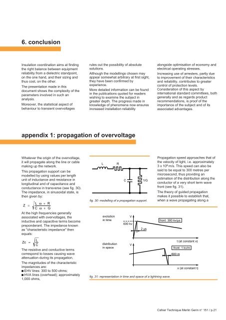
6. conclusion<strong>Insulation</strong> coordination aims at findingthe right balance between equipmentreliability from a dielectric standpoint,on the one hand, and their sizing andthus cost, on the other.The presentation made in thisdocument shows the complexity of theparameters involved in such ananalysis.Moreover, the statistical aspect ofbehaviour to transient overvoltagesrules out the possibility of absolutesolutions.Although the modellings chosen mayappear somewhat arbitrary at first sight,they have been confirmed byexperience.More detailed information can be foundin the publications quoted for readerswishing to examine the subject ingreater depth. The progress made inknowledge of phenomena now ensuresincreased installation reliabilityalongside optimisation of economy andelectrical operating stresses.Increasing use of arresters, partly dueto improvement of their characteristicsand reliability, contributes to greatercontrol of protection levels.Consideration of this aspect byinternational standard committees, bothgenerally and as regards productrecommendations, is proof of theimportance of the subject and of itsassociated advantages.appendix 1: propagation of overvoltageWhatever the origin of the overvoltage,it will propagate along the line or cablemaking up the network.This propagation support can bemodelled by using values per lengthunit of inductance and resistance inlongitudinal and of capacitance andconductance in transverse (see fig. 30).The impedance, in sinusoidal state, isthen given by:L ω + RZ =C ω + GAt the high frequencies generallyassociated with overvoltages, theinductive and capacitive terms becomepreponderant. The impedance knownas "characteristic impedance" thenequals:Lfig. 30: modelling of a propagation support.evolutionin timeRCV600 kv1/G2 µsPropagation speed approaches that ofthe velocity of light, i.e. approximately3 x 10 8 m/s. This speed can also besaid to be equal to 300 metres permicrosecond, thus providing anestimation of the distribution along theconductor of a very short term wavefront (see fig. 31).The theory of guided propagationmakes it possible to establish that,when a wave propagating along afront: 300 kv/µsLZc =CThe resistive and conductive termscorrespond to losses causing waveattenuation during its propagation.The magnitudes of the characteristicimpedances are:■ EHV lines: 300 to 500 ohms;■ HVA lines (overhead); approximately1,000 ohms,distributionin spaceVfig. 31: representation in time and space of a lightning wave.t (at constant x)front: 1 kv/m600 mx (at constant t)Cahier Technique Merlin Gerin n° 151 / p.21