Commercial Framing Systems - Ullrich Aluminium
Commercial Framing Systems - Ullrich Aluminium
Commercial Framing Systems - Ullrich Aluminium

Create successful ePaper yourself
Turn your PDF publications into a flip-book with our unique Google optimized e-Paper software.
ALUMINIUMCOMMERCIAL FRAMING SYSTEMSPRODUCT MANUALCONTENTSSECTIONGENERAL INFORMATION 1DESIGN 2WINDLOAD/MULLION SELECTION TABLES 3HUNTINGDALE FRAMING SYSTEM 4ST. GEORGE FRAMING SYSTEM 5ST. KILDA FRAMING SYSTEM 6ST. LEONARDS FRAMING SYSTEM 7PENTAGON 80 FRAMING SYSTEM 8SLIDING DOORS 9GLAZING CHANNELS AND ADAPTORS 10MANUAL NUMBER :PRINT DATE : 1st March 2005
ALUMINIUM1COMMERCIAL FRAMING SYSTEMSPRODUCT MANUALSECTION 1.PAGES – 01 to 02• GENERAL INFORMATION• INTRODUCTION• CLEANING OF ALUMINIUM• SURFACE FINISH• HANDLING AND STORAGE• FASTENERS• ISOLATION OF ALUMINIUMP1P1P2P2P2P2
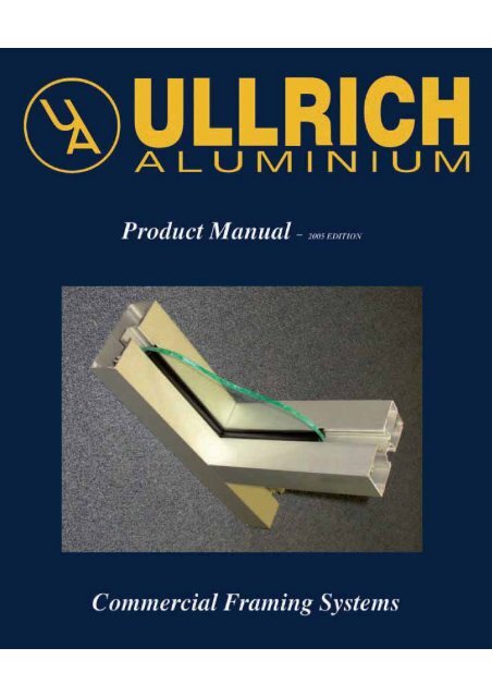
ALUMINIUMGLAZING CHANNELS & ADAPTORSSection No:Page No:Date:Replaces:1101.05.052003 EDITIONINTRODUCTIONThis Product Manual has been designed with the aim of providingSHOPFITTERS, DESIGNERS AND ARCHITECTS with acomprehensive guide to the FRAMING SYSTEMS available from<strong>Ullrich</strong> <strong>Aluminium</strong>. All systems are manufactured to the highestcommercial quality standards in respect of chemical composition,metallurgical properties, dimensional accuracy and surface finish.These systems are intended for a variety of commercial and industrialapplications such as:• SHOPFRONTS• CURTAIN WALLS• SMALL FACTORIES• OFFICE FRONTS• DOMESTIC DWELLINGSCLEANING ALUMINIUMGrime, which causes deterioration cannot be prevented from settling onexposed surfaces. If cleaned reasonably frequently then the mildestmethod of washing will produce satisfactory results.Mildest method should be tried first. The following cleaning materialsand procedures are listed in ascending order of harshness:• PLAIN WATER• MILD SOAP OR DETERGENT• KEROSENE, TURPENTINE OR WHITE SPIRIT• NON-ETCHING CHEMICAL CLEANER• WAX-BASE POLISH CLEANERAfter washing thoroughly, it should be dried with a clean cloth to preventstreakiness.DO NOT use highly caustic or abrasive cleaners.DO NOT use solvent cleaners particularly on powder coated finishes.
ALUMINIUMCOMMERCIAL FRAMING SYSTEMSPRODUCT MANUAL2SECTION 2.PAGES – 02 to 17• DESIGN• RESPONSIBILITY FOR DESIGN P1• AUSTRALIAN STANDARDS P1• CALCULATING DESIGN WIND LOADS P2BUILDING CLASSIFICATIONP2BUILDING DEFINITIONSP2SELECTING THE WIND RATINGP4REGION – AP5REGION – BP6REGION – CP7FACTORS – TERRAIN, SHIELDING, TOPOGRAPHICAL P8• CALCULATING ‘I’ SECTION REQUIRED P9• WINDOW / FRAMING FLOW CHART P10• LOAD DEFLECTION CRITERIA P11‘I’ VALUES – GRAPH 1.‘I’ VALUES – GRAPH 2.‘I’ VALUES – GRAPH 3.P12P13P14• TRANSOM DEFLECTION P15• SAMPLE CALCULATION P16• PRODUCT STRUCTURAL PROPERTIES P17
DESIGNALUMINIUMSection No:Page No:Date:Replaces:2101.05.052003 EDITIONRESPONSIBILITYThere are three prime areas of responsibility identified in the process ofspecifying, supplying and installing windows. To comply with therequirements the following procedure should be adhered to.• Firstly, the designer must provide the builder with the windclassification or loading applicable to the building• Secondly, the window manufacturer must be able to certify thatthe windows supplied will meet the specified performance.• Thirdly, the builder must ensure that the windows as supplied arelabelled or certified to the specific ratings and installed inaccordance with manufacturers installation instructions.Note: The fabricator SHOULD NOT determine the wind pressure, asthey are not qualified.RECOMMENDATIONThese tables and graphs in this manual are presented as a quick method ofcalculating the approximate structural performance of any given systemwith basic site conditions. For borderline or unusual cases, <strong>Ullrich</strong><strong>Aluminium</strong> recommends that a qualified structural engineer check calculations.Any assistance, information or recommendation supplied by <strong>Ullrich</strong><strong>Aluminium</strong> is given in good faith and believed to be appropriate for theapplication, however without any liability or responsibility on <strong>Ullrich</strong><strong>Aluminium</strong>’s part.AUSTRALIAN STANDARDSAS 2047 – 1999AS 1170 . 2-2002AS 4055Windows in BuildingsSelection and InstallationSAA Loading Code - Wind LoadsWind loads for housing
DESIGNALUMINIUMSection No:Page No:Date:Replaces:2301.05.052003 EDITIONSTEP 2: Building needs to be Defined.A house can be a Class 1 or Class 10 subject to its geometric size. AS4055 defines abuilding as follows:TABLE: 2. BUILDING DEFINITIONSReferenceFrom ground to the underside of eavesFrom gound to the highest point of roof excluding chimneyExternal wall height measured between storeysBuilding width including roofed verandahs, but excluding eavesBuilding lengthRoof pitchMaximum dimension6 m8.5 m2.7 m16 mNot to exceed 5 x widthNo greater than 35˚STEP: 3. Determine window rating.The rating is the wind pressure that the window can withstand.AS1170.2 defines window rating for residential buildings as “LIMITEDSTATE DESIGN WIND PRESSURE”AS2047.2 and AS4055 defines window rating for housing as “WINDCLASSIFICATION TERMS”The Building Window Rating is subject to ‘Individual aspects’ which canchange according to the ‘building application’ see table 3 below.TABLE: 3. WINDOW RATINGApplication Deflection Water penetrationAir infiltration L/s m 2 at testpressure - all applicationsHousing Span/150 150pa - 450pa Non Air Cond. 5.0 @ 75Padepending on8.0 @ 150Pageographic region.Residential Span/180 Air Cond 1.0 @ 75Pa1.6 @ 150Pa30% of Serviceability<strong>Commercial</strong> Span/250 Louvres 20 @ 75Pa32 @ 150Pa
DESIGNALUMINIUMSection No:Page No:Date:Replaces:2501.05.052003 EDITIONCHART 1.WINDOW RATINGS FOR RESIDENTIAL AND COMMERCIALREGION ‘A’RATING (Pa)Category 2NoYes3 StoreyNo9 StoreyYesYesServiceability = 1000Ultimate = 1800Serviceability = 1300Ultimate = 2300Category 3NoYes3 StoreyNo9 StoreyYesYesServiceability = 700Ultimate = 1200Serviceability = 1000Ultimate = 1800Category 4Yes3 StoreyNo9 StoreyYesYesServiceability = 600Ultimate = 1000Serviceability = 700Ultimate = 1200
DESIGNALUMINIUMSection No:Page No:Date:Replaces:2601.05.052003 EDITIONCHART 2.WINDOW RATINGS FOR RESIDENTIAL AND COMMERCIALREGION ‘B’RATING (Pa)Category 2NoYes3 StoreyNo9 StoreyYesYesServiceability = 1000Ultimate = 2600Serviceability = 1300Ultimate = 3300Category 3NoYes3 StoreyNo9 StoreyYesYesServiceability = 700Ultimate = 1800Serviceability = 1000Ultimate = 2600Category 4Yes3 StoreyNo9 StoreyYesYesServiceability = 600Ultimate = 1500Serviceability = 700Ultimate = 1700
DESIGNALUMINIUMSection No:Page No:Date:Replaces:2701.05.052003 EDITIONCHART 3.WINDOW RATINGS FOR RESIDENTIAL AND COMMERCIALREGION ‘C’RATING (Pa)Category 2NoYes3 StoreyNo9 StoreyYesYesServiceability = 2100Ultimate = 5000Serviceability = 2600Ultimate = 7200Category 3NoYes3 StoreyNo9 StoreyYesYesServiceability = 1400Ultimate = 4000Serviceability = 2100Ultimate = 6700Category 4Yes3 StoreyNo9 StoreyYesYesServiceability = 1200Ultimate = 4000Serviceability = 1300Ultimate = 6700
DESIGNALUMINIUMSection No:Page No:Date:Replaces:2801.05.052003 EDITIONTERRAIN CATEGORYTerrain category will range from 1 to 4 subject to obstructions that willinfluence the wind intensity on the building. See AS1170.2 clause 4.2.CATEGORY 1.WINDDIRECTIONEXPOSED OPEN TERRAIN FEW OR NO OBSTRUCTIONS.IE. HOUSES ON FLAT TREELESS, GRASSLESS AREASCATEGORY 2.WINDDIRECTIONOPEN TERRAIN, GRASSED AREAS, WITH SCATTEREDOBSTRUCTIONS. HEGHTS 1.5 - 10mCATEGORY 3.WINDDIRECTIONNUMEROUS CLOSELY SPACED OBSTRUCTIONS OFSIMILAR SIZE TO HOUSE 3m - 5mCATEGORY 4.WINDDIRECTIONNUMEROUS LARGE AND CLOSELY SPACED OBSTRUCTIONSIE. LARGE CITY CENTRES 10m - 30mSHIELDING FACTORThe shielding factor will also affect the exposure of the building. See table 4.3 AS1170.2.Usually taken as 1.0.TOPOGRAPHICAL FACTORThe wind intensity will increase if the building is located on top of a hill, ridge or steepslope. The hill shape multiplier shall be taken as 1.0 except for specific areas. SeeAS1170.2 TABLE 4.4Note:The above factors are simplified, anyone wishing to calculate the wind load/ratings isadvised to refer to the Australian Standard AS1170.2
DESIGNALUMINIUMSection No:Page No:Date:Replaces:2901.05.052003 EDITIONCALCULATING THE ‘I’ SECTION REQUIRED (if wind load is known)• From TABLE 3. (page 3) select the DEFLECTION CRITERIA.• From GRAPH 1,(pages 12-14) enter Mullion height (H) and Panel width (W)• To determine Moment of Inertia ‘I’ (second moment of area)• Use TABLE 4 (page 11) to adjust the ‘I’ in accordance with the deflectioncriteria.• From the commercial framing systems product manual select a product withmoment of inertia ‘I’ greater than calculated.• Horizontal members such as mid-rails and transoms can also be checked usinggraph 4 and 5 (page 15). In the following case the load distribution is:WWWHHHWind load on shaded area transferred to mullion.Note:• Horizontal members need to be checked to ensure that the membercan support the glass dead load. See graph 4 and 5 (page 15).• Usually the critical structural member is the vertical mullion orcombination of shapes dividing adjacent sheets of glass.• The wind load on the glass is assumed to be evenly distributed andtransferred to mullion. See shaded area in the diagram below.L (H)AverageHeightTransom• The mullion is considered as a simply supported beam. No end restraint.• Deflection is usually the limiting factor. Stress cannot be discounted.
DESIGNALUMINIUMSection No:Page No:Date:Replaces:21001.05.052003 EDITIONWINDOW AND FRAMING FLOW CHARTIs the buildingresidential?NoIs the building height< 10mNoIs the building height< 30mYesUSE AS1170.2, AS2047 for design of wind load.OR - USE charts 1 - 3 (page 5 - 7).To determine ‘I’ value use graphs 1 - 3 (page 12-14)Span/250 serviceability limitNoYesYesUSE AS1170.2, AS2047 for design of wind load.OR - USE charts 1 - 3 (page 5 - 7).To determine ‘I’ value use graphs 1 - 3 (page 12-14)Span/250 serviceability limitUSE AS1170.2, AS2047 for design of wind load.OR - USE charts 1 - 3 (page 5 -7).To determine ‘I’ value use graphs 1 - 3 (page 12-14)Span/250 serviceability limitIs the residentialbuilding a house?YesDoes the house fallwithin the limits of AS4055, Clause 6?YesUSE charts 1 - 3 (page 5-7). for design of wind load.To determine ‘I’ value use graphs 1 - 3 (page 12-14)Span/150 serviceability limitNoNoUSE AS1170.2, for design of wind load.OR - USE charts 1 - 3 (page 5 -7).To determine ‘I’ value use graphs 1 - 3 (page 12-14)Span/180 serviceability limitIs the building height< 10mYesUSE AS1170.2, for design of wind load.OR - USE charts 1 - 3 (page 5 -7).To determine ‘I’ value use graphs 1 - 3 (page 12-14)Span/180 serviceability limitNoIs the building height< 30mNoYesUSE AS1170.2, for design of wind load.OR - USE charts 1 - 3 (page 5 -7).To determine ‘I’ value use graphs 1 - 3 (page 12-14)Span/180 serviceability limitUSE AS1170.2, for design of wind load.OR - USE charts 1 - 3 (page 5 -7).To determine ‘I’ value use graphs 1 - 3 (page 12-14)Span/180 serviceability limit
DESIGNALUMINIUMSection No:Page No:Date:Replaces:21101.05.052003 EDITIONTABLE 4: MULTIPLYING FACTORS FOR ALTERNATIVELOAD AND DEFLECTION CRITERIALoad Span Span Span Span(pascals) 150 180 250 360500 0.3 0.36 0.50 0.72600 0.36 0.43 0.60 0.86700 0.42 0.50 0.70 1.01800 0.48 0.58 0.80 1.151000 0.60 0.72 1.00 1.441200 0.72 0.86 1.20 1.731500 09.0 1.08 1.50 2.162000 1.20 1.44 2.00 2.882500 1.50 1.80 2.50 3.603000 1.80 2.16 3.00 4.323500 2.10 2.52 3.50 5.044000 2.40 2.88 4.00 5.76
DESIGNALUMINIUMSection No:Page No:Date:Replaces:21201.05.052003 EDITIONGRAPH 1. (determines ‘I’ values)1900WW1800H1700Height of Mullion (mm)160015001400130012001100100010090807060504030Moment of Inertia (second moment of area) ‘I’ x 10 3 mm 49002080010700300 500 700 900 1100 1300 1500 1700 1900 2000Panel Width (mm)Load: 1000 PascalsDeflection Span250Note: Use tables 4 (page 11) to adjust ‘I’ for alternative load and deflection criteria
DESIGNALUMINIUMSection No:Page No:Date:Replaces:21301.05.052003 EDITIONGRAPH 2. (determines ‘I’ values)5000WWHHeight of Mullion (mm)40003000200020001750150012501000900800700600500400300200Moment of Inertia (second moment of area) ‘I’ x 10 3 mm 41501000300 500 700 900 1100 1300 1500 1700 1900 2000Panel Width (mm)Load: 1000 PascalsDeflection Span250Note: Use tables 4 (page 11) to adjust ‘I’ for alternative load and deflection criteria
DESIGNALUMINIUMSection No:Page No:Date:Replaces:21401.05.052003 EDITIONGRAPH 3. (determines ‘I’ values)7000WWH6000Height of Mullion (mm)50004000300012000115001100010500100009500900085008000750070006500600055005000450040003500300025002000Moment of Inertia (second moment of area) ‘I’ x 10 3 mm 42000300 500 700 900 1100 1300 1500 1700 1900 2000Panel Width (mm)Load: 1000 PascalsDeflection Span250Note: Use tables 4 (page 11) to adjust ‘I’ for alternative load and deflection criteria
DESIGNALUMINIUMSection No:Page No:Date:Replaces:21501.05.052003 EDITIONDEFLECTION OF TRANSOM DUE TO DEAD LOAD OF GLASSThe graphs below indicate sizes of 6mm and 10mm glass supported at quarter points producean arbitrary mid span deflection of 3mm in transom. In certain situations such asover doorways little or no deflection can be tolerated. Mid span deflection can be reducedby supporting the glass closer to the ends, rather than at the quarter points. Rememberthat the ‘I’ section obtained from the graphs is about the horizontal axis.GRAPH: 4.Deflection (with 6mm Glass)400050 100 150 200 300 400 5001 value x 10 3 mm 4 of transomHeight of glass (mm)3000200010006mm glassSH09001200 1500 1800 2100 2400 2700 3000Span of transom (mm)GRAPH: 5.Deflection (with 10mm Glass)400050 100 150 200 300 400 5001 value x 10 3 mm 4 of transomHeight of glass (mm)30002000100010mm glassSH09001200 1500 1800 2100 2400 2700 3000Span of transom (mm)
ALUMINIUMSection No:Page No:Date:Replaces:21601.05.052003 EDITIONEXAMPLE27001200TRANSOMS DO NOTADD STRUCTURALSTRENGTH TO MULLIONSDATA:STEP: 1.<strong>Commercial</strong> building, 5 Storey, 15m High, Location Sydney.‘Building located in Sydney’ - ‘Region’ = ‘A’(see maps - Page 5-7)STEP: 2. ‘Building is in commercial area’ - ‘Terrain Category’ = ‘4’(see page 8)STEP: 3.‘Building is <strong>Commercial</strong> and less than 30m high’(from flow chart page 10) - Serviceability limit = SPANor table 3 250STEP: 4. ‘Wind Rating’ can now be obtained (from pages 5-7)Known data: Region = ‘A’, Category = ‘4’, Building height =greater than 3 storey.Window Rating = 700 Pa (Serviceability)STEP: 5.Now need to select a section with a ‘Moment of Inertia’ thatwill take the wind pressure. (from graphs pages 12-14)Known data: Height of Mullion = 2700mm, Panel Width=1200mm.Locate point where Mullion Height and Panel Width crosses.Follow graph (curved lines) to edge of graph read Moment ofInertia = 1050 x 10 3 mm 4STEP: 6. Now need to adjust Ixx for ‘site conditions’. (from table 4 Page11 ).Known data: Wind Load = 700 Pa,Deflection Criteria = SPAN250(From table 4 page 11) – Multiplying factor = 0.7Revised Ixx = 1050 x 10 3 mm 4 x 0.7 = 735 x 10 3 mm 4STEP: 7. Select mullion with Ixx greater than 735. (from table 5 page 17).IE. USE AS7106 WITH AS 7110Which has an Ixx value of 848 x 10 3 mm 4
DESIGNALUMINIUMSection No:Page No:Date:Replaces:21701.05.052003 EDITIONTABLE 5: PRODUCT SELECTIONIxx Iyy PART Nosx 10 3 mm 4 x 10 3 mm 4210 137 AS405215 156 AS961253 AS977, AS7891, AS7891262 AS50313, AS50313, AS10311267 124 AS8034, AS8033278 AS8205, AS8204, AS7891284 187 ST850, AS7771295 201 ST850, AS10486303 AS50320, AS50320405 51 AS4424, AS4425482 27 AS8130594 75 AS9969, AS9969601 84 AS8I31621 69 AS8556, AS7109650 89 AS7107, AS7109, AS7111680 220 AS805, AS7112, AS7125682 79 AS8557, AS8558782 AS878, AS7891, AS7891807 AS7557, AS7558, AS7891820 133 AS7906, AS7110848 102 AS7106, AS7110869 126 AS10251, AS10252, AS10253876 115 AS7106, AS7109887 85 AS7115, AS7116939 AS972, AS7891, AS7891950 AS7777, AS7778, AS7891976 154 AS10250, AS10253986 AS50320, AS503121000 137 AS7703, AS71101066 AS50423, AS50423, AS103111130 480 ST863, AS77711150 481 ST863, AS104861219 96 FU1048, FU10481240 149 AS7704, AS77051398 502 AS7117, AS71101415 166 AS7975, AS79741515 242 AS806, AS7112, AS71251686 329 AS50312, AS503121803 196 AS10370, AS103691900 58 UN00242, UN002422082 212 UN00239, ME71092140 214 AS8278, AS82782290 276 AS30271, AS302712431 161 AS8274, AS82763123 645 AS0969, AS77713140 648 AS0969, AS104863150 257 AS8280, AS73453194 190 AS8273, AS73453230 212 AS8273, AS82753246 340 AS807, AS7112, AS71254020 135 AS8277, AS82774398 208 AS8281, AS82826570 811 987-358, AS77716590 815 987-358, AS10486
ALUMINIUMCOMMERCIAL FRAMING SYSTEMSPRODUCT MANUALSECTION – 3.PAGES – 01 to 073• WIND LOAD / MULLIONSELECTION TABLES• AS7106 / AS7109• AS8556 / AS7109• AS10253 / AS10251• FU1048 / FUI048• AS8278 / AS8278• AS30271 / AS30271• AS8273 / AS8275• AS8277 / AS8277• UN00242 / UN00242• UN00239 / UN00239P1P1P2P2P3P3P4P4P5P5‘I’xx for TRANSOM/MIDRAILTRANSOMMIDRAILP6P7
ALUMINIUMMULLION SELECTIONSection No:Page No:Date:Replaces:3101.05.052003 EDITIONMULLION STRENGTHSThe following wind load tables have been produced asa guide to assist in the selection of a suitable framingsection. Values are based on theoretical properties of theextruded sections together with tests performed by aNATA approved testing laboratory as specified inAS2047 1999.Ixx = 876 x 10 3 mm 4Iyy = 115 x 10 3 mm 4Yield Stress = 110 MpaS = Serviceability - (deflection limited pressure) span/250U = Ultimate limit state pressureYXAS 7106AS 7109YIxx = 621 x 10 3 mm 4Iyy = 70 x 10 3 mm 4Yield Stress = 110 MpaXMullionHeight (mm)Pressure kPa3800 S 0.429 - - - - - - -U 1.117 - - - - - - -3600 S 0.505 - - - - - - -U 1.244 - - - - - - -3400 S 0.599 0.479 - - - - - -U 1.395 1.116 - - - - - -3200 S 0.719 0.575 0.479 0.411 - - - -U 1.575 1.260 1.050 0.900 - - - -3000 S 0.872 0.698 0.581 0.498 0.436 - - -U 1.791 1.433 1.194 1.024 0.896 - - -2800 S 1.073 0.858 0.715 0.613 0.536 0.477 0.429 -U 2.057 1.645 1.371 1.175 1.028 0.914 0.823 -2600 S 1.340 1.072 0.893 0.766 0.670 0.595 0.536 0.487U 2.385 1.908 1.590 1.363 1.193 1.060 0.954 0.8672400 S 1.703 1.363 1.136 0.973 0.852 0.757 0.681 0.619U 2.799 2.239 1.866 1.600 1.400 1.244 1.120 1.0182200 S 2.211 1.769 1.474 1.264 1.106 0.983 0.885 0.804U 3.331 2.665 2.221 1.904 1.666 1.481 1.332 1.2112000 S 2.943 2.355 1.962 1.682 1.472 1.308 1.177 1.070U 4.031 3.225 2.687 2.303 2.015 1.791 1.612 1.466Mullion spacing (mm) 800 1000 1200 1400 1600 1800 2000 2200S = Serviceability- (deflection limited pressure) span/250U = Ultimate limit state pressureXAS 8556YYAS 7109XMullionHeight (mm)Pressure kPa3400 S 0.425 - - - - - - -U 0.989 - - - - - - -3200 S 0.509 - - - - - - -U 1.116 - - - - - - -3000 S 0.618 0.495 0.412 - - - - -U 1.270 1.016 0.847 - - - - -2800 S 0.760 0.608 0.507 0.435 - - - -U 1.458 1.166 0.972 0.833 - - - -2600 S 0.950 0.760 0.633 0.543 0.475 0.422 - -U 1.691 1.353 1.127 0.966 0.845 0.751 - -2400 S 1.208 0.966 0.805 0.690 0.604 0.537 0.483 0.439U 1.984 1.587 1.323 1.134 0.992 0.882 0.794 0.7222200 S 1.568 1.254 1.045 0.896 0.784 0.697 0.627 0.570U 2.362 1.889 1.574 1.349 1.181 1.050 0.945 0.8592000 S 2.087 1.669 1.391 1.192 1.043 0.927 0.835 0.759U 2.857 2.286 1.905 1.633 1.429 1.270 1.143 1.039Mullion spacing (mm) 800 1000 1200 1400 1600 1800 2000 2200
ALUMINIUMMULLION SELECTIONMULLION STRENGTHSSection No:Page No:Date:Replaces:3201.05.052003 EDITIONThe following wind load tables have been produced asa guide to assist in the selection of a suitable framingsection. Values are based on theoretical properties of theextruded sections together with tests performed by aNATA approved testing laboratory as specified inAS2047 1999.XAS 10253XIxx = 976 x 10 3 mm 4Iyy = 154 x 10 3 mm 4Yield Stress = 110 MpaYXYIxx = 1220 x 10 3 mm 4Iyy = 96 x 10 3 mm 4Yield Stress = 110 MpaFU 1048YAS 10250FU 1048XYS = Serviceability - (deflection limited pressure) span/250U = Ultimate limit state pressureMullionHeight (mm)Pressure kPa4000 S 0.410 - - - - - - -U 1.123 - - - - - - -3800 S 0.478 - - - - - - -U 1.244 - - - - - - -3600 S 0.562 0.450 - - - - - -U 1.386 1.109 - - - - - -3400 S 0.667 0.534 0.445 - - - - -U 1.554 1.243 1.036 - - - - -3200 S 0.801 0.641 0.534 0.458 - - - -U 1.754 1.403 1.170 1.002 - - - -3000 S 0.972 0.777 0.648 0.555 0.486 0.432 - -U 1.996 1.597 1.331 1.141 0.998 0.887 - -2800 S 1.195 0.956 0.797 0.683 0.598 0.531 0.478 0.435U 2.291 1.833 1.528 1.309 1.146 1.018 0.917 0.8332600 S 1.493 1.194 0.995 0.853 0.746 0.663 0.597 0.543U 2.657 2.126 1.772 1.518 1.329 1.181 1.063 0.9662400 S 1.898 1.518 1.265 1.084 0.949 0.843 0.759 0.690U 3.119 2.495 2.079 1.782 1.559 1.386 1.247 1.1342200 S 2.464 1.971 1.643 1.408 1.232 1.095 0.986 0.896U 3.712 2.969 2.474 2.121 1.856 1.650 1.485 1.3502000 S 3.279 2.623 2.186 1.874 1.640 1.457 1.312 1.192U 4.491 3.593 2.994 2.566 2.245 1.996 1.796 1.633Mullion spacing (mm) 800 1000 1200 1400 1600 1800 2000 2200S = Serviceability- (deflection limited pressure) span/250U = Ultimate limit state pressureMullionHeight (mm)Pressure kPa4200 S 0.442 - - - - - - -U 1.272 - - - - - - -4000 S 0.512 0.410 - - - - - -U 1.402 1.122 - - - - - -3800 S 0.597 0.478 - - - - - -U 1.554 1.243 - - - - - -3600 S 0.702 0.562 0.468 - - - - -U 1.731 1.385 1.154 - - - - -3400 S 0.834 0.667 0.556 0.476 0.417 - - -U 1.941 1.553 1.294 1.109 0.970 - - -3200 S 1.000 0.800 0.667 0.571 0.500 0.444 - -U 2.191 1.753 1.461 1.252 1.096 0.974 - -3000 S 1.214 0.971 0.809 0.693 0.607 0.539 0.485 0.441U 2.493 1.994 1.662 1.425 1.246 1.108 0.997 0.9072800 S 1.493 1.194 0.995 0.853 0.746 0.663 0.597 0.543U 2.862 2.289 1.908 1.635 1.431 1.272 1.145 1.0412600 S 1.864 1.491 1.243 1.065 0.932 0.829 0.746 0.678U 3.319 2.655 2.213 1.897 1.659 1.475 1.328 1.2072400 S 2.370 1.896 1.580 1.354 1.185 1.053 0.948 0.862U 3.895 3.116 2.597 2.226 1.948 1.731 1.558 1.4162200 S 3.077 2.462 2.052 1.758 1.539 1.368 1.231 1.119U 4.636 3.708 3.090 2.649 2.318 2.060 1.854 1.6862000 S 4.096 3.277 2.731 2.340 2.048 1.820 1.638 1.489U 5.609 4.487 3.739 3.205 2.805 2.493 2.244 2.040Mullion spacing (mm) 800 1000 1200 1400 1600 1800 2000 2200
ALUMINIUMMULLION SELECTIONSection No:Page No:Date:Replaces:3301.05.052003 EDITIONMULLION STRENGTHSThe following wind load tables have been produced asa guide to assist in the selection of a suitable framingsection. Values are based on theoretical properties of theextruded sections together with tests performed by aNATA approved testing laboratory as specified inAS2047 1999.Ixx = 2140 x 10 3 mm 4Iyy = 214 x 10 3 mm 4Yield Stress = 110 MpaXIxx = 2290 x 10 3 mm 4Iyy = 276 x 10 3 mm 4Yield Stress = 110 MpaXAS8278AS 30271YYAS8278XYAS 30271XYS = Serviceability - (deflection limited pressure) span/250U = Ultimate limit state pressureMullionHeight (mm)Pressure kPa4200 S 0.775 0.620 0.517 0.443 - - - -U 2.229 1.783 1.486 1.274 - - - -4000 S 0.897 0.718 0.598 0.513 0.449 - - -U 2.457 1.966 1.638 1.404 1.229 - - -3800 S 1.046 0.837 0.698 0.598 0.523 0.465 0.419 -U 2.723 2.178 1.815 1.556 1.361 1.210 1.089 -3600 S 1.231 0.984 0.820 0.703 0.615 0.547 0.492 0.447U 3.034 2.427 2.022 1.733 1.517 1.348 1.213 1.1033400 S 1.461 1.169 0.974 0.835 0.730 0.649 0.584 0.531U 3.401 2.721 2.267 1.943 1.700 1.512 1.360 1.2373200 S 1.752 1.402 1.168 1.001 0.876 0.779 0.701 0.637U 3.839 3.071 2.560 2.194 1.920 1.706 1.536 1.3963000 S 2.127 1.701 1.418 1.215 1.063 0.945 0.851 0.773U 4.368 3.495 2.912 2.496 2.184 1.941 1.747 1.5882800 S 2.618 2.092 1.744 1.495 1.308 1.162 1.046 0.951U 5.015 4.012 3.343 2.865 2.507 2.229 2.006 1.8232600 S 3.267 2.613 2.178 1.867 1.633 1.452 1.307 1.188U 5.816 4.653 3.877 3.323 2.908 2.585 2.326 2.1152400 S 4.153 3.323 2.769 2.373 2.077 1.846 1.661 1.510U 6.825 5.460 4.550 3.900 3.413 3.034 2.730 2.4822200 S 5.392 4.314 3.595 3.081 2.696 2.397 2.157 1.961U 8.123 6.498 5.415 4.642 4.061 3.610 3.249 2.9542000 S 7.177 5.742 4.785 4.101 3.588 3.190 2.871 2.610U 9.829 7.863 6.552 5.616 4.914 4.368 3.931 3.574Mullion spacing (mm) 800 1000 1200 1400 1600 1800 2000 2200S = Serviceability- (deflection limited pressure) span/250U = Ultimate limit state pressureMullionHeight (mm)Pressure kPa4200 S 0.830 0.664 0.553 0.474 0.415 - - -U 2.386 1.909 1.591 1.364 1.193 - - -4000 S 0.961 0.768 0.640 0.549 0.480 0.427 - -U 2.631 2.105 1.754 1.503 1.315 1.169 - -3800 S 1.120 0.896 0.747 0.640 0.560 0.498 0.448 -U 2.915 2.332 1.943 1.666 1.458 1.296 1.166 -3600 S 1.318 1.054 0.878 0.753 0.659 0.586 0.527 0.479U 3.248 2.598 2.165 1.856 1.624 1.444 1.299 1.1813400 S 1.564 1.251 1.043 0.894 0.782 0.695 0.626 0.569U 3.641 2.913 2.428 2.081 1.821 1.618 1.457 1.3243200 S 1.876 1.501 1.251 1.072 0.938 0.834 0.750 0.682U 4.111 3.289 2.740 2.349 2.055 1.827 1.644 1.4953000 S 2.277 1.821 1.518 1.301 1.138 1.012 0.911 0.828U 4.677 3.742 3.118 2.673 2.339 2.079 1.871 1.7012800 S 2.800 2.240 1.867 1.600 1.400 1.245 1.120 1.018U 5.369 4.295 3.579 3.068 2.685 2.386 2.148 1.9522600 S 3.498 2.798 2.332 1.999 1.749 1.555 1.399 1.272U 6.227 4.981 4.151 3.558 3.113 2.767 2.491 2.2642400 S 4.447 3.558 2.965 2.541 2.223 1.976 1.779 1.617U 7.308 5.846 4.872 4.176 3.654 3.248 2.923 2.6572200 S 5.773 4.619 3.849 3.299 2.887 2.566 2.309 2.099U 8.697 6.958 5.798 4.970 4.348 3.865 3.479 3.1632000 S 7.684 6.147 5.123 4.391 3.842 3.415 3.074 2.794U 10.523 8.419 7.016 6.013 5.262 4.677 4.209 3.827Mullion spacing (mm) 800 1000 1200 1400 1600 1800 2000 2200
ALUMINIUMMULLION SELECTIONMULLION STRENGTHSSection No:Page No:Date:Replaces:3401.05.052003 EDITIONThe following wind load tables have been produced asa guide to assist in the selection of a suitable framingsection. Values are based on theoretical properties of theextruded sections together with tests performed by aNATA approved testing laboratory as specified inAS2047 1999.Ixx = 3230 x 10 3 mm 4Iyy = 212 x 10 3 mm 4Yield Stress = 110 MpaXXYIxx = 4020 x 10 3 mm 4Iyy = 135 x 10 3 mm 4Yield Stress = 110 MpaXAS 8273AS 8277YYAS 8275AS 8277XYS = Serviceability - (deflection limited pressure) span/250U = Ultimate limit state pressureMullionHeight (mm)Pressure kPa4200 S 1.172 0.937 0.781 0.669 0.586 0.521 0.469 0.426U 2.245 1.796 1.496 1.283 1.122 0.998 0.898 0.8164000 S 1.356 1.085 0.904 0.775 0.678 0.603 0.542 0.493U 2.475 1.980 1.650 1.414 1.237 1.100 0.990 0.9003800 S 1.582 1.265 1.055 0.904 0.791 0.703 0.633 0.575U 2.742 2.194 1.828 1.567 1.371 1.219 1.097 0.9973600 S 1.860 1.488 1.240 1.063 0.930 0.827 0.744 0.676U 3.055 2.444 2.037 1.746 1.528 1.358 1.222 1.1113400 S 2.208 1.767 1.472 1.262 1.104 0.981 0.883 0.803U 3.425 2.740 2.283 1.957 1.713 1.522 1.370 1.2463200 S 2.649 2.119 1.766 1.514 1.324 1.177 1.060 0.963U 3.867 3.093 2.578 2.210 1.933 1.719 1.547 1.4063000 S 3.215 2.572 2.143 1.837 1.607 1.429 1.286 1.169U 4.399 3.520 2.933 2.514 2.200 1.955 1.760 1.6002800 S 3.954 3.163 2.636 2.259 1.977 1.757 1.582 1.438U 5.050 4.040 3.367 2.886 2.525 2.245 2.020 1.8372600 S 4.938 3.951 3.292 2.822 2.469 2.195 1.975 1.796U 5.857 4.686 3.905 3.347 2.929 2.603 2.343 2.1302400 S 6.279 5.023 4.186 3.588 3.139 2.790 2.511 2.283U 6.874 5.499 4.583 3.928 3.437 3.055 2.750 2.5002200 S 8.151 6.521 5.434 4.658 4.076 3.623 3.261 2.964U 8.181 6.545 5.454 4.675 4.090 3.636 3.272 2.9752000 S 9.899 7.919 6.599 5.656 4.949 4.399 3.959 3.600U 9.899 7.919 6.599 5.656 4.949 4.399 3.959 3.600Mullion spacing (mm) 800 1000 1200 1400 1600 1800 2000 2200S = Serviceability- (deflection limited pressure) span/250U = Ultimate limit state pressureMullionHeight (mm)Pressure kPa4200 S 1.457 1.166 0.971 0.833 0.729 0.648 0.583 0.530U 2.790 2.232 1.860 1.594 1.395 1.240 1.116 1.0144000 S 1.687 1.349 1.124 0.964 0.843 0.750 0.675 0.613U 3.076 2.461 2.051 1.758 1.538 1.367 1.230 1.1183800 S 1.967 1.574 1.312 1.124 0.984 0.874 0.787 0.715U 3.408 2.726 2.272 1.947 1.704 1.515 1.363 1.2393600 S 2.314 1.851 1.542 1.322 1.157 1.028 0.925 0.841U 3.797 3.038 2.532 2.170 1.899 1.688 1.519 1.3813400 S 2.747 2.197 1.831 1.569 1.373 1.221 1.099 0.999U 4.257 3.406 2.838 2.433 2.129 1.892 1.703 1.5483200 S 3.294 2.636 2.196 1.883 1.647 1.464 1.318 1.198U 4.806 3.845 3.204 2.746 2.403 2.136 1.922 1.7483000 S 3.998 3.199 2.665 2.285 1.999 1.777 1.599 1.454U 5.468 4.374 3.645 3.125 2.734 2.430 2.187 1.9882800 S 4.918 3.934 3.278 2.810 2.459 2.186 1.967 1.788U 6.277 5.022 4.185 3.587 3.139 2.790 2.511 2.2832600 S 6.142 4.914 4.095 3.510 3.071 2.730 2.457 2.233U 7.280 5.824 4.853 4.160 3.640 3.236 2.912 2.6472400 S 7.809 6.247 5.206 4.462 3.904 3.471 3.124 2.840U 8.544 6.835 5.696 4.882 4.272 3.797 3.418 3.1072200 S 10.138 8.110 6.759 5.793 5.069 4.506 4.055 3.687U 10.168 8.134 6.779 5.810 5.084 4.519 4.067 3.6972000 S 12.303 9.843 8.202 7.030 6.152 5.468 4.921 4.474U 12.303 9.843 8.202 7.030 6.152 5.468 4.921 4.474Mullion spacing (mm) 800 1000 1200 1400 1600 1800 2000 2200Note: Italics represents limit state pressure governs over deflection limited pressure
ALUMINIUMMULLION SELECTIONMULLION STRENGTHSSection No:Page No:Date:Replaces:3501.05.052003 EDITIONThe following wind load tables have been produced asa guide to assist in the selection of a suitable framingsection. Values are based on theoretical properties of theextruded sections together with tests performed by aNATA approved testing laboratory as specified inAS2047 1999.Ixx = 1900 x 10 3 mm 4Iyy = 58 x 10 3 mm 4Yield Stress = 110 MpaXUN 00242YYUN 00242XIxx = 2082 x 10 3 mm 4Iyy = 212 x 10 3 mm 4Yield Stress = 110 MpaXUN 00239YYME 7109XS = Serviceability - (deflection limited pressure) span/250U = Ultimate limit state pressureMullionHeight (mm)Pressure kPa4200 S 0.688 0.550 0.458 - - - - -U 1.339 1.071 0.893 - - - - -4000 S 0.796 0.637 0.531 0.455 - - - -U 1.477 1.181 0.984 0.844 - - - -3800 S 0.928 0.743 0.619 0.530 0.464 0.413 - -U 1.636 1.309 1.091 0.935 0.818 0.727 - -3600 S 1.092 0.873 0.728 0.624 0.546 0.485 0.437 -U 1.823 1.458 1.215 1.042 0.911 0.810 0.729 -3400 S 1.296 1.037 0.864 0.741 0.648 0.576 0.518 0.471U 2.044 1.635 1.362 1.168 1.022 0.908 0.817 0.7433200 S 1.554 1.244 1.036 0.888 0.777 0.691 0.622 0.565U 2.307 1.846 1.538 1.318 1.154 1.025 0.923 0.8393000 S 1.887 1.509 1.258 1.078 0.943 0.838 0.755 0.686U 2.625 2.100 1.750 1.500 1.312 1.167 1.050 0.9552800 S 2.320 1.856 1.547 1.326 1.160 1.031 0.928 0.844U 3.013 2.411 2.009 1.722 1.507 1.339 1.205 1.0962600 S 2.898 2.319 1.932 1.656 1.449 1.288 1.159 1.054U 3.495 2.796 2.330 1.997 1.747 1.553 1.398 1.2712400 S 3.685 2.948 2.456 2.106 1.842 1.638 1.474 1.340U 4.101 3.281 2.734 2.344 2.051 1.823 1.641 1.4912200 S 4.784 3.827 3.189 2.734 2.392 2.126 1.914 1.740U 4.881 3.905 3.254 2.789 2.441 2.169 1.952 1.7752000 S 5.906 4.725 3.937 3.375 2.953 2.625 2.362 2.148U 5.906 4.725 3.937 3.375 2.953 2.625 2.362 2.148Mullion spacing (mm) 800 1000 1200 1400 1600 1800 2000 2200Note: Italics represents limit state pressure governs over deflection limited pressureMullionHeight (mm)Pressure kPa4200 S 0.755 0.604 0.504 0.432U 1.837 1.469 1.224 1.0504000 S 0.874 0.700 0.583 0.500 0.437U 2.025 1.620 1.350 1.157 1.0133800 S 1.020 0.816 0.680 0.583 0.510 0.453U 2.244 1.795 1.496 1.282 1.122 0.9973600 S 1.200 0.960 0.800 0.685 0.600 0.533 0.480 0.436U 2.500 2.000 1.667 1.429 1.250 1.111 1.000 0.9093400 S 1.424 1.139 0.949 0.814 0.712 0.633 0.570 0.518U 2.803 2.242 1.869 1.602 1.401 1.246 1.121 1.0193200 S 1.708 1.366 1.139 0.976 0.854 0.759 0.683 0.621U 3.164 2.531 2.109 1.808 1.582 1.406 1.266 1.1513000 S 2.073 1.658 1.382 1.184 1.036 0.921 0.829 0.754U 3.600 2.880 2.400 2.057 1.800 1.600 1.440 1.3092800 S 2.549 2.040 1.700 1.457 1.275 1.133 1.020 0.927U 4.133 3.306 2.755 2.362 2.066 1.837 1.653 1.5032600 S 3.184 2.547 2.123 1.819 1.592 1.415 1.274 1.158U 4.793 3.834 3.195 2.739 2.396 2.130 1.917 1.7432400 S 4.048 3.239 2.699 2.313 2.024 1.799 1.619 1.472U 5.625 4.500 3.750 3.214 2.813 2.500 2.250 2.0452200 S 5.256 4.205 3.504 3.003 2628 2.336 2.102 1.911U 6.694 5.355 4.463 3.825 3.347 2.975 2.678 2.4342000 S 6.996 5.596 4.664 3.997 3.498 3.109 2.798 2.544U 8.100 6.480 5.400 4.629 4.050 3.600 3.240 2.945Mullion spacing (mm) 800 1000 1200 1400 1600 1800 2000 2200S = Serviceability- (deflection limited pressure) span/250U = Ultimate limit state pressure
ALUMINIUMTRANSOM SELECTIONSection No:Page No:Date:Replaces:3601.05.052003 EDITIONGRAPH 6:GLASS ‘DEAD LOAD’ ON TRANSOMThis graph can be used to select the ‘I’ (moment of inertia) required by a transom to support theweight of glass.(Based on a deflection of 3mm and glass supported at quarter points). Note: By increasing the ‘I’value by 2 will reduce the deflection to half. IE. 1.5mmNOTE: Loads due to wind will need to be calculated separately.Weight of Glass in (Kg/Metre length of transom)1008060402050100 150 200160'I' Value x 10 3 mm 401.0 1.1 1.2 1.3 1.4 1.5 1.6 1.7 1.8 1.9 2.0Length of Transom in (M)HOW TO USE THE GRAPH• To calculate Weight of Glass / Metre length of transomMultiply Glass Weight / m 2 x Glass panel Height.• Knowing the Weight of Glass and Transom Widthfrom graph plot the intersection point.Follow the curved lines to the top of the graph andread ‘I’ value required.select a transom with ‘I’ greater than required.GLASS DETAILThickness Weight/M 24mm 10.0Kg5mm 12.5Kg6mm 15.0Kg8mm 20.0Kg10mm 25.0KgEXAMPLE:• A fixed unit using 6mm glass, 1.6m wide x 2.4m high.• Glass Weight x Height = (15 x 2.4) = 36 Kg/ m length of transom• From graph plot intersection of 1.6m and 36 Kg = 160 x 10 3 mm 4• Select AS8278/AS8278 which has an ‘Iyy’ of 214 x 10 3 mm 4
ALUMINIUMMIDRAIL SELECTIONSection No:Page No:Date:Replaces:3701.05.052003 EDITIONGRAPH 7:GLASS ‘DEAD LOAD’ ON MIDRAILThis graph can be used to select the ‘I’ required by a midrail to support the weight of glass.(Based on a deflection of 3mm and glass supported at quarter points). Note: By increasing the ‘I’value by 2 will reduce the deflection to half. IE. 1.5mmNOTE: Loads due to wind will need to be calculated separately.Weight of Glass in (Kg/Metre length of transom)1008060402050100'I' Value x 10 3 mm 4150 20001.0 1.1 1.2 1.3 1.4 1.5 1.6 1.7 1.8 1.9 2.0Panel Width in Metres (Transom Length)HOW TO USE THE GRAPH210300 400 500 600 700• To calculate Weight of Glass / Metre length of transomMultiply Glass Weight / m 2 x Glass panel Height.• Knowing the Weight of Glass and Transom Widthfrom graph plot the intersection point.Follow the curved lines to the top of the graph andread ‘I’ value required.select a transom with ‘Ixx’ greater than required.GLASS DETAILThickness Weight/M 24mm 10.0Kg5mm 12.5Kg6mm 15.0Kg8mm 20.0Kg10mm 25.0KgEXAMPLE:• A fixed unit using 6mm glass, 1.8m wide x 2.0 high.• Glass Weight x Height = (15 x 2.0) = 30 Kg/ m length of transom• From graph plot intersection of 1.8m and 30 Kg = 210 x 10 3 mm 4• Select AS805/AS7112/AS7125 which has an ‘Ixx’ of 680 x 10 3 mm 4OR AS8278/AS8278 (on side) which has an ‘Iyy’ of 214 x 10 3 mm 4
ALUMINIUMCOMMERCIAL FRAMING SYSTEMSPRODUCT MANUALSECTION 4.PAGES – 01 to 27• HUNTINGDALE FRAMING SYSTEM4• 401, 402 SERIES FEATURES P1• 401,402 SERIES GLAZING NOTES P2• 401,402 SERIES COMPONENTS P3 - 9• 401,402 SERIES ASSEMBLY DRAWINGS P10 - 11• 403 SERIES FEATURES P12• 403 SERIES GLAZING NOTES P13• 403 SERIES COMPONENTS P14• 403 SERIES ASSEMBLY DRAWINGS P15 - 16• 601 SERIES FEATURES P17• 601 SERIES COMPONENTS P18 - 20• 601 SERIES ASSEMBLY DRAWINGS P21• SOLARIUM COMPONENTS P22• SOLARIUM ASSEMBLY DRAWINGS P23 – 24• STRUCTURAL PROPERTIES OF SECTIONS P25 - 27
ALUMINIUMHUNTINGDALE FRAMING SYSTEMSection No:Page No:Date:Replaces:4101.05.052003 EDITIONFEATURES: (series 401, 402)• Simple to install• Centre glazing• Accepts glass thickness from 5mm to 10mm• Ranges of Sizes - 101.6 x 44.5, 101.6 x 101.6 x 152.5 x 44.5mullions to 200 mm door mid-rails.• Built-in drainage minimising potential water leaks• All screw flutes are standard 10 gauge• Designed for both wet and dry weather glazing• Pocket grooves allows for flush glazing and contains the P.V.C.wedgesNOTES:1. Sub-sills should be used in extreme weatherconditions. Remember to fix stop ends2. Dry glazing is not recommended for shopfronts inextreme weather conditions3. Allow for mullion expansion or contraction inareas that are subject to thermal movement10 # SCREWFLUTE44.576.2 crs101.6
ALUMINIUMHUNTINGDALE FRAMING SYSTEMSection No:Page No:Date:Replaces:4201.05.052003 EDITIONDaylight 8Dry GlazingP.V.C. GlazingWedgeDaylight 8Wet Glazing19 Pocket 19 PocketSilicone SealGlazing TapeSilicone Seal88Setting BlockGlass Dry Glazing Wet GlazingInside Wedge Outside Wedge Inside Outside Wedge5 mm 343-5 343-5 Silicone & Tape 343-56 mm 343-6 343-6 Silicone & Tape 343-66.38 mm Y113 Y113 Silicone & Tape Y1138 mm 343-8 343-8 Silicone & Tape 343-810 mm 114-10 114-10 Silicone & Tape 114-10GLASS CUTTING SIZE; Height & Width = Daylight + 16 mmBecause of tolerances in P.V.C. wedges and extrusion the above recommendations should beused as a guide only.GLAZING NOTES:DRY GLAZING: One side must have a removable bead. Position setting blocks (2) approx _ 1 /4width in from the edge. Use silicone to eliminate them from moving. Place glass panel into thepocket resting on the setting blocks. Position the glass and install temporary wedges on bothsides of glass.Cut wedges approx. 5% oversize and place in warm soapy water.Insert wedge starting from ends. Remove temporary ones as you go.Fit wedges to both sides before proceeding to either the sill or head.Seal all corners with black silicone.Glazing from one side is possible using captive wedges. These are inserted into one side of thepocket, the glass is then inserted and wedge fitted to the other side.343-5 343-6 Y113 343-8 114-10(5mm Glass) (6mm Glass) (6.38mm Glass) (8mm Glass) (10mm Glass)
ALUMINIUMHUNTINGDALE FRAMING SYSTEMSection No:Page No:Date:Replaces:4301.05.052003 EDITION101.61944.5AS7106HEAD / MULLIONWT = 1.426Kg/mAP = 527mmPP = 187mmAS7111SILL BEADWT = 0.345Kg/mAP = 177mmPP = 100mmAS7107SILLWT = 1.233Kg/mAP = 445mmPP = 125mmAS7109POCKETED FILLERWT = 0.777Kg/mAP = 312mmPP = 100mm
ALUMINIUMHUNTINGDALE FRAMING SYSTEMSection No:Page No:Date:Replaces:4401.05.052003 EDITIONFU1048SELF-MATIINGMULLION LIGHTWT = 1.367Kg/mAP = 475mmPP = 210mmAS8278SELF-MATIINGMULLION HEAVYWT = 2.623Kg/mAP = 515mmPP = 127mmAS7115C.O.C. TRANSOMWT = 1.458Kg/mAP = 458mmPP = 149mmAS7116C.O.C. TRANSOMWT = 0.479Kg/mAP = 229mmPP = 116mm
ALUMINIUMHUNTINGDALE FRAMING SYSTEMSection No:Page No:Date:Replaces:4501.05.052003 EDITIONAS71172 & 3 WAY CORNERWT = 2.172Kg/mAP = 698mmPP = 211mmAS7110FLAT FILLERWT = 0.492Kg/mAP = 206mmPP = 100mmAS808AWNINGWT = 0.687Kg/mAP = 340mmPP = 150mmAS7112GLAZING BEADWT = 0.207Kg/mAP = 122mmPP = 60mm
ALUMINIUMHUNTINGDALE FRAMING SYSTEMSection No:Page No:Date:Replaces:4601.05.052003 EDITIONALCP0173SUB SILLWT = 0.921Kg/mAP = 400mmPP = 115mmAS10391SUB SILLWT = 1.118Kg/mAP = 418mmPP = 100mmFU1036SUB SILLWT = 1.097Kg/mAP = 419mmPP = 100mm
ALUMINIUMHUNTINGDALE FRAMING SYSTEMSection No:Page No:Date:Replaces:4701.05.052003 EDITIONAS7912SUB HEADWT = 1.474Kg/mAP = 449mmPP = 225mmAS8131PLAIN MULLIONWT = 0.981Kg/mAP = 443mmPP = 208mmAS8130NARROW PERIMETER FRAMEWT = 1.126Kg/mAP = 461mmPP = 152mmAS10389SUB SILLWT = 1.195Kg/mAP = 462mmPP = 115mm
ALUMINIUMHUNTINGDALE FRAMING SYSTEMSection No:Page No:Date:Replaces:4801.05.052003 EDITIONAS7561SUB SILLWT = 1.669Kg/mAP = 497mmPP = 114mmAS7795SUB SILLWT = 2.139Kg/mAP = 462mmPP = 100mmADAPTORSAS7114DOOR STOPWT = 0.291Kg/mAP = 147mmPP = 147mmAS7113POCKET FILLERWT = 0.184Kg/mAP = 108mmPP = 100mmAS7124AWNING SASH ADAPTORWT = 0.30Kg/mAP = 163mmPP = 100mmAS8279DOOR STOPWT = 0.297Kg/mAP = 151mmPP = 100mmAS7118GLAZING ADAPTORWT = 0.499Kg/mAP = 187mmPP = 100mmAS7112GLAZING BEADWT = 0.207Kg/mAP = 122mmPP = 100mm
ALUMINIUMHUNTINGDALE FRAMING SYSTEMSection No:Page No:Date:Replaces:4901.05.052003 EDITIONAS8556MAIN FRAMEWT = 1.235Kg/mAP = 536mmPP = 187mmAS8558GLAZING BEADWT = 0.277Kg/mAP = 180mmPP = 100mmAS8557SILLWT = 1.050Kg/mAP = 456mmPP = 125mm
ALUMINIUMHUNTINGDALE FRAMING SYSTEMSection No:Page No:Date:Replaces:41001.05.052003 EDITION16944.51AS7109AS57106122 7 1013Glass = daylight + 168191723 4151620 2122544.528 8AS7111AS7107AS71098 11Typical ElevationDaylight8AS7111AS710744.53AS710937 Daylight84AS7111AS710740 Daylight85AS7111AS7107AS7561AS7795
ALUMINIUMHUNTINGDALE FRAMING SYSTEMSection No:Page No:Date:Replaces:41101.05.052003 EDITION101.6AS7110AS7117AS7109AS7109AS7117AS71098Daylight101.6817 18HS7124AS7110AS7106AS7112AS8089819
ALUMINIUMHUNTINGDALE FRAMING SYSTEMSection No:Page No:Date:Replaces:41201.05.052003 EDITIONFEATURES: (Series 403)• Simple to install• Centre glazing• Accepts 25mm double glazed units• Heavier than 44.5mm for greater spans• Built-in drainage minimising potential water leaks• Flexibility of design-different mullion sections can be used• All screw flutes are standard 10 gauge• Designed for both wet and dry weather glazing• Pocket grooves allows for flush glazing and contains the P.V.C.wedgesNOTES:1. Sub-sills should be used in extreme weatherconditions. Remember to fix stop ends.2. Dry glazing is not recommended for shopfronts inextreme weather conditions.3. Allow for mullion expansion or contraction inareas that are subject to thermal movement.2576.2crs501033.2101.6
ALUMINIUMHUNTINGDALE FRAMING SYSTEMSection No:Page No:Date:Replaces:41301.05.052003 EDITION33.2SPACER (FULL LENGTH)(by others)WEDGE10 DAYLIGHTGLASSDRY GLAZING---------- ---------------------25 mm 343-6 WEDGE Inside and outsideGLAZING NOTES:DRY GLAZING: One side must have a removable bead. Position setting blocks (2) approx 1 /4width in from the edge. Use silicone to eliminate them from moving. Place glass panel into thepocket resting on the setting blocks. Position the glass and install temporary wedges on bothsides of glass.Cut wedges approx. 5% oversize and place in warm soapy water.Insert wedge starting from ends. Remove temporary ones as you go.Fit wedges to both sides before proceeding to either the sill or head.Seal all corners with black silicone.Glazing from one side is possible using captive wedges. These are inserted into one side of thepocket, the glass is then inserted and wedge fitted to the other side.
ALUMINIUMHUNTINGDALE FRAMING SYSTEMSection No:Page No:Date:Replaces:41401.05.052003 EDITIONAS10250 HEAD / JAMB MULLIONWT = 1.473Kg/mAP = 560mmPP = 174mmAS10252 BEADWT = 0.336Kg/mAP = 174mmPP = 100mmAS10254 DOOR STOPWT = 0.370Kg/mAP = 186mmPP = 100mmAS10251 SILLWT = 1.289Kg/mAP = 466mmWT = 0.803Kg/mAP = 325mmPP = 100mmAS10253 GLAZING ADAPTORAS7110 FLUSH FILLERWT = 0.492Kg/mAP = 207mmPP = 100mmAS30104 AWNING SASH STOPWT = 0.340Kg/mAP = 187mmPP = 100mmAS7744 25mm BEADWT = 0.184Kg/mAP = 100mmPP = 100mmAS30271 H/D SELF MATING MULLIONWT = 2.423Kg/mAP = 555mmPP = 112mmAS976 AWNING SASHWT = 0.686Kg/mAP = 220mmPP = 154mm
ALUMINIUMHUNTINGDALE FRAMING SYSTEMSection No:Page No:Date:Replaces:41501.05.052003 EDITION502050DAYLIGHT10 10DAYLIGHTGLASS = DAYLIGHT + 20101050GLASS = DAYLIGHT +231AS10252AS10252AS7110AS10250AS10251AS10253AS10251DAYLIGHT 50DAYLIGHT50 DAYLIGHTGLASS = DAYLIGHT + 24105AS976SASH = DAYLIGHT - 72AS976104AS10250AS30104 AS1025310 10AS7744AS30104 AS10253AS10250
ALUMINIUMHUNTINGDALE FRAMING SYSTEMSection No:Page No:Date:Replaces:41601.05.052003 EDITION10AS30271AS30271AS30271AS302716 6GLASS = DAYLIGHT + 20DAYLIGHT50 DAYLIGHT50DAYLIGHTAS10250AS10250AS7110AS71107108GLASS = DAYLIGHT + 2050 DAYLIGHT50 DAYLIGHTAS10250AS7110AS10250AS800AS8029 10AS10254AS10253DAYLIGHT50 DOOR DAYLIGHT 50 DOORREBATEREBATE
ALUMINIUMHUNTINGDALE FRAMING SYSTEMSection No:Page No:Date:Replaces:41701.05.052003 EDITIONFEATURES: (Series 601)• Simple to install• Centre glazing• Accepts glass thickness from 5mm to 10mm• Frame size 152mm x 44.5mm designed for greater spans• Built-in drainage minimising potential water leaks• All screw flutes are standard 10 gauge• Designed for both wet and dry weather glazing• Pocket grooves allows for flush glazing and contains the P.V.C.wedgesNOTES:1. Sub-sills should be used in extreme weatherconditions. Remember to fix stop ends2. Dry glazing is not recommended for shopfronts inextreme weather conditions3. Allow for mullion expansion or contraction inareas that are subject to thermal movement152.510# SCREWFLUTE44.572.6crs
ALUMINIUMHUNTINGDALE FRAMING SYSTEMSection No:Page No:Date:Replaces:41801.05.052003 EDITION152.544.5AS8273HEAD / JAMB / MULLIONWT = 2.539Kg/mAP = 649mmPP = 248mmAS8275POCKET FILLERWT = 1.201Kg/mAP = 400mmPP = 110mmAS8276BEADWT = 0.440Kg/mAP = 229mmPP = 100mmAS8274SILLWT = 2.227Kg/mAP = 570mmPP = 162mm
ALUMINIUMHUNTINGDALE FRAMING SYSTEMSection No:Page No:Date:Replaces:41901.05.052003 EDITIONUN00239MAIN FRAMEWT = 13.215Kg/mAP = 729mmPP = 310mmUN00242SELF MATING MULLIONWT = 12.149Kg/mAP = 577mmPP = 225mm
ALUMINIUMHUNTINGDALE FRAMING SYSTEMSection No:Page No:Date:Replaces:42001.05.052003 EDITIONAS8277SELF MATING MULLIONWT = 2.198Kg/mAP = 572mmPP = 111mmAS7345FLAT FILLERWT = 0.930Kg/mAP = 310mmPP = 127mmAS10009SUBSILLWT = 2.037Kg/mAP = 562mmPP = 115mm
ALUMINIUMHUNTINGDALE FRAMING SYSTEMSection No:Page No:Date:Replaces:42101.05.052003 EDITION1AS827544.5 44.5Daylight44.5Daylight + 168 82320 X 6 DrainageslotsAS8276AS8276AS8273AS8274AS8275AS8274AS8273AS804AS71121.6 thk foldedsub-sillAS8275AS8277AS8277AS8273AS827564 8 8 5710Daylight + 1644.5 Daylight44.5
ALUMINIUMHUNTINGDALE FRAMING SYSTEMSection No:Page No:Date:Replaces:42201.05.052003 EDITIONAS405GLAZING BAR MULLIONWT = 1.732Kg/mAP = 393mmPP = 200mmAS42742 WAY CORNERWT = 0.472Kg/mAP = 237mmPP = 100mmAS6355AWNING SASHWT = 0.865Kg/mAP = 307mmPP = 166mmAS7124GLAZING BAR MULLIONWT = 0.300Kg/mAP = 164mmPP = 100mmNB 1104AWNING SASHCORNER STAKEWT = 0.851Kg/mAP = 204mmPP = N/ANB 7700GLAZING BARCORNER STAKEWT = 6.156Kg/mAP = 551mmPP = N/A
ALUMINIUMHUNTINGDALE FRAMING SYSTEMSection No:Page No:Date:Replaces:42301.05.052003 EDITIONFLASHING25 X 25 ANGLE1AS7106SILICONEJOINTNB 7700CORNERSPIGOT23˚2500 MAX.50x25 ANGLE2AS7111AS7107AS7561
ALUMINIUMHUNTINGDALE FRAMING SYSTEMSection No:Page No:Date:Replaces:42401.05.052003 EDITIONAS6355AS71246AS40525 X 25 ANGLEAS7106AS405AS427438 DAYLIGHT 8DAYLIGHT + 1645
FU1048ALUMINIUMHUNTINGDALE FRAMING SYSTEMYSection No:Page No:Date:Replaces:42501.05.052003 EDITIONXAS7106AS7109XIxx = 876.6 x 10 3 mm 4Iyy = 115 x 10 3 mm 4AS7112YAS807AS7112XAS8278YXYYXXAS8278AS7111YIxx = 2140 x 10 3 mm 4Iyy = 214 x 10 3 mm 4XAS7109YYAS7107XIxx = 650 x 10 3 mm 4Iyy = 89 x 10 3 mm 4AS7112AS7112YIxx = 3246 x 10 3 mm 4Iyy = 340 x 10 3 mm 4XYXIxx = 1220 x 10 3 mm 4FU1048XAS7115AS7116XIxx = 887 x 10 3 mm 4Iyy = 85 x 10 3 mm 4YAS7112YYYYAS7112XIyy = 96 x 10 3 mm 4 Ixx = 848 x 10 3 mm 4AS806XXXXAS805XAS7106AS7110AS7125YAS805Ixx = 680 x 10 3 mm 4Iyy = 220 x 10 3 mm 4 Ixx = 1515 x 10 3 mm 4Iyy = 242 x 10 3 mm 4YYIyy = 102 x 10 3 mm 4
ALUMINIUMHUNTINGDALE FRAMING SYSTEMSection No:Page No:Date:Replaces:42601.05.052003 EDITIONYYAS10250XXAS10253AS30271XXIxx = 976 x 10 3 mm 4Ixx = 2290 x 10 3 mm 4Iyy = 154 x 10 3 mm 4Iyy = 276 x 10 3 mm 3YXXIxx = 869 x 10 3 mm 4Iyy = 126 x 10 3 mm 4AS10253AS10252AS10251AS30271YYY
ALUMINIUMHUNTINGDALE FRAMING SYSTEMSection No:Page No:Date:Replaces:42701.05.052003 EDITIONYYAS8273AS7345AS8277AS8277XXXXYYIxx = 3194 x 10 3 mm 4Ixx = 4020 x 10 3 mm 4Iyy = 190 x 10 3 mm 4Iyy = 135 x 10 3 mm 4YAS405XXYIxx = 210 x 10 3 mm 4Iyy = 137 x 10 3 mm 4
ALUMINIUMCOMMERCIAL FRAMING SYSTEMSPRODUCT MANUALSECTION 5.PAGES – 01 to 16• ST. GEORGE FRAMING SYSTEM• FEATURES – EXTERNALLY GLAZED P15• NOTES – EXTERNALLY GLAZED P2• COMPONENTS – EXTERNALLY GLAZED P3 - 6• SIZE LIMITATIONS – WINDOW/STAYS P7• STAY SELECTION CHARTS P8• ASSEMBLY DRAWINGS – EXTERNALLY GLAZED P9 - 10• FEATURES – INTERNALLY GLAZED P11• NOTES – INTERNALLY GLAZED P12• COMPONENTS – INTERNALLY GLAZED P13• ASSEMBLY DRAWINGS – INTERNALLY GLAZED P14 - 15• STRUCTURAL PROPERTIES OF SECTIONS P16
ALUMINIUMST. GEORGE FRAMING SYSTEMSection No:Page No:Date:Replaces:5101.05.052003 EDITIONFEATURES:• Highly versatile – permitting a wide range of design freedom• High performance commercial class window and framing system• Accepts glass thickness from 4 to 14mm and 25mm• Corner stakes with double seal sash• Aesthetics completely changed by using square or bevelled beads68.5101.67232
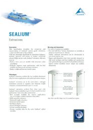
ALUMINIUMST. GEORGE FRAMING SYSTEMSection No:Page No:Date:Replaces:5201.05.052003 EDITION3513.5 1.5Glass=Daylight + 2512.5 DaylightGlass=Daylight + 2512.5 Daylight30.5 1.5Notch bead toreceive settingblock.GLAZING POCKET DESCRIPTIONGlass ............... 4 to 14mm and 25mm thickGlass cutting size... Daylight + 25mmMATERIAL BEADS GLASS TAPE SHIM WEDGETHICKNESS SIZE DIA. NoAll framing AE7891 4mm 8 x 5 3mm 343-6members NB7559 5mm 8 x 5 3mm 343-86mm 8 x 5 3mm 114-108mm 8 x 5 3mm Y113NB10172 12mm 8 x 5 3mm 114-10NB7744 25mm 8 x 5 3mm Y113NOTES:because of tolerances on metal, glass and glazing materials, these recommendations should be taken as a guideonly and should be verified and modified if required to suit actual job materials
ALUMINIUMST. GEORGE FRAMING SYSTEMSection No:Page No:Date:Replaces:5301.05.052003 EDITION101.645AS7557FEMALE FRAMEWT = 0.904Kg/mAP = 404mmPP = 198mm25AS7558MALE FRAMEWT = 0.815Kg/mAP = 389mmPP = 176mmAS878TUBULAR FRAMEWT = 0.1.799Kg/mAP = 375mmPP = 375mmAS8089DOOR JAMBWT = 0.672Kg/mAP = 326mmPP = 148mm
ALUMINIUMST. GEORGE FRAMING SYSTEMSection No:Page No:Date:Replaces:5401.05.052003 EDITION68.545AS8205FEMALE FRAMEWT = 0.687Kg/mAP = 322mmPP = 177mm25AS8204MALE FRAMEWT = 0.627Kg/mAP = 323mmPP = 201mmAS977TRANSOMWT = 1.252Kg/mAP = 306mmPP = 306mm
ALUMINIUMST. GEORGE FRAMING SYSTEMSection No:Page No:Date:Replaces:5501.05.052003 EDITIONAS7560SUB HEADWT = 1.148Kg/mAP = 370mmPP = 187mmAS10389SUB SILLWT = 1.195Kg/mAP = 462mmPP = 115mmAS10171SUBHEADWT = 0.853Kg/mAP = 308mmPP = 152mmAS10011SUB SILLWT = 0.960Kg/mAP = 363mmPP = 100mm
ALUMINIUMST. GEORGE FRAMING SYSTEMSection No:Page No:Date:Replaces:5601.05.052003 EDITIONAdaptors, Sash and BeadsAdaptors, Sash and BeadsAS7559BEVEL BEADWT = 0.177Kg/mAP = 124mmPP = 100mmAS7891SQUARE BEADWT = 0.206Kg/mAP = 144mmPP = 100mmAS774425mm BEADWT = 0.184Kg/mAP = 100mmPP = 100mm138-040DOOR STOPAS976AWNING SASHWT = 0.686Kg/mAP = 220mmPP = 154mmAS1017212mm BEADWT = 0.190Kg/mAP = 134mmPP = 100mm
ALUMINIUMST. GEORGE FRAMING SYSTEMSection No:Page No:Date:Replaces:5701.05.052003 EDITIONWAWNING WINDOWH = Max 1200mm, Min 350mmW = Max 1300mmHMax Area = 1.80m 2NOTE:Sashes up to 1000mm wide - 1 cam handleSashes over 1000mm wide - 2 cam handlesWCASEMENT WINDOWH = Max 1200mmW = Max 650mm, Min 350mmMax Area = 0.78 2HNOTE:Sashes up to 1000mm high - 1 cam handleSashes over 1000mm high - 2 cam handlesReference to Standard Publication:AS1170.2 - 2002AS2047 - 1999- SAA Loading Code - wind loads- Windows in Building (Selection and installation)NOTES:Stays should be selected in accordance with manufacturers load recommendations and fitted toprovide slight compression to bulb seals when sash is in closed position. Cam Handles or ChainWinders can be used and should be fitted securely to sash frame or bead. If fitted to the beadsensible care should be exercised in pulling the sash closed to avoid twisting the bead off.
ALUMINIUMST. GEORGE FRAMING SYSTEMSection No:Page No:Date:Replaces:5801.05.052003 EDITION1.71.71.61.51.4500A830A1.61.51.4500A830ASASH HEIGHT (m)1.31.21.11.00.90.80.7330A230ASASH HEIGHT (m)1.31.21.11.00.90.80.7330A230A0.60.60.50.4230V0.50.4230V0.3 0.4 0.5 0.6 0.7 0.8 0.9 1.0 1.1 1.2 1.3SASH WIDTH (m)4mm GLASS0.3 0.4 0.5 0.6 0.7 0.8 0.9 1.0 1.1 1.2 1.3SASH WIDTH (m)5mm GLASS1.71.71.61.5500A830A1.61.5500A1.41.41.31.3SASH HEIGHT (m)1.21.11.00.90.80.70.6330A230ASASH HEIGHT (m)1.21.11.00.90.80.70.6330A230A830A0.50.4230V0.50.4230V0.3 0.4 0.5 0.6 0.7 0.8 0.9 1.0 1.1 1.2 1.3SASH WIDTH (m)6mm GLASS0.3 0.4 0.5 0.6 0.7 0.8 0.9 1.0 1.1 1.2 1.3SASH WIDTH (m)4mm DOUBLE GLASS1.71.71.61.6830A1.51.41.3500A830A1.51.41.3500ASASH HEIGHT (m)1.21.11.00.90.80.70.6330A230ASASH HEIGHT (m)1.21.11.00.90.80.70.6330A230A0.50.50.4230V0.4230V0.3 0.4 0.5 0.6 0.7 0.8 0.9 1.0 1.1 1.2 1.3SASH WIDTH (m)5mm DOUBLE GLASS0.3 0.4 0.5 0.6 0.7 0.8 0.9 1.0 1.1 1.2 1.3SASH WIDTH (m)6mm DOUBLE GLASS
ALUMINIUMST. GEORGE FRAMING SYSTEMSection No:Page No:Date:Replaces:5901.05.052003 EDITION18295FFF4 6 7310FFTYPICAL ELEVATIONO/A FRAME72 45Glass = Daylight + 251512.5 Daylight 12.51 BULBSEAL2AS87889AS7891AS7559AS976AS878AS7560BULBSEALSASH =DAYLIGHT + 60AS7557AS7560AS75593AS755710AS7557DrainageAS7561AS10389
ALUMINIUMST. GEORGE FRAMING SYSTEMSection No:Page No:Date:Replaces:51001.05.052003 EDITION3 67.5AS 7557AS 8089AS 8019Daylight7Daylight12.548Spacer support (by others)AS 7558AS 7557AS 7557AS 87812.5 Daylight 12.5Glass = Daylight + 254 512.5 Daylight12.5Glass = Daylight + 25645 7272DaylightQ/A FRAME
ALUMINIUMST. GEORGE FRAMING SYSTEMSection No:Page No:Date:Replaces:51101.05.052003 EDITIONFEATURES:• High performance commercial class window and framing system• Accepts glass thickness from 4 to 14mm and 25mm• External fin provides:1. external glass face2. internal glazing3. greater rentable areaNOTE:This is a fixed light system and does not readily adapt to Awning/Casementwindows sashes101.6357232
ALUMINIUMST. GEORGE FRAMING SYSTEMSection No:Page No:Date:Replaces:51201.05.052003 EDITION1.513.5Glass =Daylight + 2512.5DaylightGlass =Daylight + 2512.5Daylight1.5 30.5notch bead toreceive settingblock1GLAZING POCKET DESCRIPTIONGlass ............... 4 to 8mm and 25mm thickGlass cutting size... Daylight + 25mmMATERIAL BEADS GLASS TAPE SHIM WEDGETHICKNESS SIZE DIA. NoAll framing AE7891 4mm 8 x 5 3mm 343-6members NB7559 5mm 8 x 5 3mm 343-86mm 8 x 5 3mm 114-108mm 8 x 5 3mm Y113NB10172 12mm 8 x 5 3mm 114-10NB7744 25mm 8 x 5 3mm Y113NOTES:because of tolerances on metal, glass and glazing materials, these recommendations should be taken as a guideand should be verified or modified as required to suit actual job materials.
ALUMINIUMST. GEORGE FRAMING SYSTEMSection No:Page No:Date:Replaces:51301.05.052003 EDITION101.645AS 7777FEMALE FRAMEWT = 0.961Kg/mAP = 398mmPP = 144mm25AS 7778MALE FRAMEWT = 0.853Kg/mAP = 383mmPP = 102mmAS 972TUBULAR FRAMEWT = 0.961Kg/mAP = 398mmPP = 144mm
ALUMINIUMST. GEORGE FRAMING SYSTEMSection No:Page No:Date:Replaces:51401.05.052003 EDITION194251086 7311Typical Elevation32O/A FRAME45 724515AS7560AS7777AS7560Glass = Daylight + 25Glass = Daylight + 2512312.5 12.512.5DaylightDaylight12.5AS7559AS7778AS7777AS777791011AS7891AS972Drainageslots20 x 6DRAINAGESLOTSAT 450 ctsAS10389DrainageAS7561
ALUMINIUMST. GEORGE FRAMING SYSTEMSection No:Page No:Date:Replaces:51501.05.052003 EDITIONAS7777AS7778412.5 Daylight12.5Glass = Daylight + 25545 72O/A FRAMEAS7778AS8089AS8029 DaylightAS7559SUPPORT SPACER BY OTHERSDaylight12.548Doorrebate8AS774412.5 Daylight 12.56 7Glass = Daylight + 2572 45O/A FRAME
ALUMINIUMST. GEORGE FRAMING SYSTEMSection No:Page No:Date:Replaces:51601.05.052003 EDITIONYYXAS 977XXAS 8205AS 8204XAS10172YAS10172AS 7891 AS 7891YIxx = 278 x 10 3 mm 4YXIxx = 253 x 10 3 mm 4 Ixx = 950 x 10 3 mm 4YAS 878XXAS 7777AS 7778XAS 7891 AS 7891AS10172AS10172YIxx = 782 x 10 3 mm 4YYYXAS 7557AS 7558XAS 972XXAS 7891 AS 7891AS10172 AS10172YIxx = 807 x 10 3 mm 4YIxx = 939 x 10 3 mm 4
ALUMINIUMCOMMERCIAL FRAMING SYSTEMSPRODUCT MANUALSECTION 6PAGES – 01 to 07• ST. KILDA FRAMING SYSTEM6• FEATURES• GLAZING NOTESP1P2• COMPONENTS P3 - 4• ASSEMBLY DRAWINGS P5 - 6• STRUCTURAL PROPERTIES OF SECTIONSP7
ALUMINIUMST. KILDA FRAMING SYSTEMSection No:Page No:Date:Replaces:6101.05.052003 EDITIONFEATURES:(ST. KILDA SUITE)• Accepts glass thickness from 6mm to 16mm• Concealed bracket fixing• Glass is located on external edge• Range of sizes from 50, 100, 150, and 200mm• Flush smooth faces inside and out• Accepts the Huntingdale door system• ‘Snap - on’ external covers, sealed with sealantNOTES:• Sub sills should be used in extreme weather conditions. Remember to fix stop ends• Dry glazing is not recommended for shopfronts in extreme weather conditions• Not recommended on a building higher than 3 storeysConcealed Bracket50.8Varies from 50 up to 200
ALUMINIUMST. KILDA FRAMING SYSTEMSection No:Page No:Date:Replaces:6201.05.052003 EDITIONBack glazingadaptor variesSilicone beadsealContinuousspacer19 16or 28.5pocket50, 100, 150 or 200FrontadaptorTape andshim50.8Glazing pocket descriptionMethod ............................................Tape, continuous spacer with silicone bead seal.Glass................................................6 mm to 16 mm, depending on back adaptor used.Glass cutting size ............................Daylight + 25 mm or frame centre - 25 mm.MATERIAL SPECIFICATION:BACK GLASS TAPE SHIM SPACERADAPTOR THICKNESS SIZE DIA. DIA.AS7771 6mm 10 x 5 3mm 8mm8mm 10 x 5 3mm 6mmAS10486 12mm 12 x 8 5mm 12mm16mm 12 x 8 5mm 10mm
ALUMINIUMST. KILDA FRAMING SYSTEMSection No:Page No:Date:Replaces:6301.05.052003 EDITIONAS 7770Snap AdaptorWT = 0.366 kg/mAP = 188mmPP = 100mmAS 1048613mm Back AdaptorWT = 0.915 kg/mAP = 167mmPP = 167mmAS 7769Front AdaptorWT = 0.505 kg/mAP = 125mmPP = 125mmAS 77716mm Back AdaptorWT = 0.667 kg/mAP = 140mmPP = 140mm
ALUMINIUMST. KILDA FRAMING SYSTEMSection No:Page No:Date:Replaces:6401.05.052003 EDITIONWT = 1.287 kg/mAP = 200mmPP = 200mmST850(SH502 . 5MI6 . 5L)WT = 3.154 kg/mAP = 400mmPP = 400mmWT = 3.967 kg/mAP = 500mmPP = 500mmWT = 2.348 kg/mAP = 300mmPP = 300mmAS0969(RH150503MI6 . 5L)ST863(RH100503MI6 . 5L)987 - 358(RH200503MI6 . 5L)
ALUMINIUMST. KILDA FRAMING SYSTEMSection No:Page No:Date:Replaces:6501.05.052003 EDITION150234
ALUMINIUMST. KILDA FRAMING SYSTEMSection No:Page No:Date:Replaces:6601.05.052003 EDITION5Box Section(As req'd)367.5AS 8019 DaylightBack adaptors (as req'd)Front adaptorsAS77696 7Snap adaptorsAS7770
ALUMINIUMST. KILDA FRAMING SYSTEMSection No:Page No:Date:Replaces:6701.05.052003 EDITIONRefer toColumn 1Box sectionXNB7770Snap adaptorYYNB7769Front adaptorXRefer toColumn 2Back adaptor'H'EXTRUSIONSTRUCTURAL PROPERTIESCOLUMN COLUMN DIMENSION MOMENT OF INERTIA.( x 10 3 mm 4 )1 2 H mm Ixx IyyST850 AS7771 85 284 187ST850 D1830 97 295 201ST863 AS7771 135 1130 480ST863 D1830 149 1150 481AS0969 AS7771 185 3123 645AS0969 D1830 197 3140 648987-358 AS7771 235 6570 811987-358 D1830 247 6590 815
ALUMINIUMCOMMERCIAL FRAMING SYSTEMSPRODUCT MANUALSECTION – 7.PAGES – 01 to 12• ST. LEONARDS FRAMING SYSTEM• FEATURES P1• GLAZING DETAILS P27• COMPONENTS P3 - 8• ASSEMBLY DRAWINGS P9 - 11• STRUCTURAL PROPERTIES OF SECTIONS P12
ALUMINIUMST LEONARDS FRAMING SYSTEMSection No:Page No:Date:Replaces:7101.05.052003 EDITIONFEATURES:(ST LEONARDS SUITE)NOTES:• Screw spline construction• 50mm wide mullions and perimeter frames• Glass is located on external edge• Range of sizes from 53.5mm, 103.5mm to 150.0mm• Mullions are split to accommodate expansion/contraction• Accepts glass thickness 6mm to 10mm using snap cover NB7707 and up to 14mmthickness using snap cover NB8315• Accepts the Huntingdale door system• Range of structural glazed mullions or mullions with snap on covers• Designed for both wet and dry glazing• Sub sills should be used in extreme weather conditions. Remember to fix stop ends• Dry glazing is not recommended for shopfronts in extreme weather conditions• Not recommended on a building higher than 2 storeys• <strong>Ullrich</strong> Metals does not support 4 sided structural glazing, but will allow 2 sided withsnap covers on the remaining 2 sidesAS7704AS7705AS7975AS79743.5 16 103.650 50Structurally glazed withStructurally glazedsnap on Cover
ALUMINIUMST LEONARDS FRAMING SYSTEMSection No:Page No:Date:Replaces:7201.05.052003 EDITIONContinuous GlazingTape16Silicon SealP.V.C. Captive WedgeALC27-121Snap Cover12.5Wet Glazing: Without Snap covers(STRUCURAL GLAZING)Continuous Glazing Tape5 18Dry Glazing: (NOT FOR EXTERNAL USE)Foam Tape16Foam TapeCompressed 25%on assembly12.5AS8034 & AS961 with AS7707 provide an 18mm pocket, & with AS 8315 a 22mm pocket.AS30250 provides, with 4" and 150 St Leonards and AS 7707, a 35mm pocket.
ALUMINIUMST LEONARDS FRAMING SYSTEMSection No:Page No:Date:Replaces:7301.05.052003 EDITION103.5AS7703Head, Jamb, TransomWT = 1.231kg/mAP = 526mmPP = 230mm50AS7110Flush fillerWT = 0.492kg/mAP = 207mmPP = 100mmAS7704Male MullionWT = 1.065kg/mAP = 419mmPP = 136mmAS7705Female MullionWT = 1.031kg/mAP = 396mmPP = 171mm
ALUMINIUMST LEONARDS FRAMING SYSTEMSection No:Page No:Date:Replaces:7401.05.052003 EDITION103.5AS7906Structural GlazedTransomWT = 1.179kg/mAP = 500mmPP = 243mm50AS7975Structural GlazedMale MullionWT = 1.145kg/mAP = 441mmPP = 140mmAS7974Structural GlazedFemale MullionWT = 1.234kg/mAP = 467mmPP = 189mmAS50050Structural GlazedTransomWT = 1.513kg/mAP = 331mmPP = 331mm
ALUMINIUMST LEONARDS FRAMING SYSTEMSection No:Page No:Date:Replaces:7501.05.052003 EDITIONWT = 1.017kg/mAP = 387mmPP = 154mmAS9413Concealed MullionDrainageWT = 1.669kg/mAP = 496mmPP = 114mmAS7561Sub-sill SlottedWT = 2.139kg/mAP = 463mmPP = 100mmDrainageAS7795Sub-sill SlottedWT = 0.921kg/mAP = 400mmPP = 115mmALCP0173Sub-sill Curtain Wall
ALUMINIUMST LEONARDS FRAMING SYSTEMSection No:Page No:Date:Replaces:7601.05.052003 EDITION150AS8280Head, Jamb, TransomWT = 2.555kg/mAP = 676mmPP = 284mm50AS8281Male Mullion HeavyWT = 2.130kg/mAP = 500mmPP = 181mmAS8282Female Mullion HeavyWT = 2.096kg/mAP = 472mmPP = 217mmAS10009SubsillWT = 2.037kg/mAP = 562mmPP = 115mm
ALUMINIUMST LEONARDS FRAMING SYSTEMSection No:Page No:Date:Replaces:7701.05.052003 EDITION53.5AS8034Narrow MaleMullionWT = 1.156kg/mAP = 267mmPP = 158mm50WT = 0.874kg/mAP = 328mmPP = 95mmAS961Narrow TransomWT = 0.808kg/mAP = 295mmPP = 125mmAS10370Heavy Male MullionWT = 1.767kg/mAP = 376mmPP = 170mmAS8033Narrow FemaleMullionAS10369Heavy Female MullionWT = 1.928kg/mAP = 404mmPP = 134mm103.5
ALUMINIUMST LEONARDS FRAMING SYSTEMSection No:Page No:Date:Replaces:7801.05.052003 EDITIONAS7706AdaptorWT = 0.394kg/mAP = 156mmPP = 100mmWT = 1.287kg/mAP = 200mmPP = 200mmST850 (SH502•5MI6•5L)50x50x2.5 BoxWT = 2.665kg/mAS7707AP = 190mmSnap cover PP = 100mmMax. Glass thk.=10mm25x10# Pan.Hds/s screw.AS7708Snap infill coverWT = 0.490kg/mAP = 214mmPP = 100mmALC27-121Snap coverP.V.C. WedgeAS3025025mmGlass AdaptorWT = 0.431kg/mAS8315 AP = 206mmSnap cover PP = 100mmMax. Glass thk.=14mmWT = 0.295kg/mAP = 148mmPP = 100mm
ALUMINIUMST LEONARDS FRAMING SYSTEMSection No:Page No:Date:Replaces:7901.05.052003 EDITION65012 50Daylight 50Daylight12.5 12.5 12.5 12.5Glass = daylight + 25Glass = daylight + 25123AS7707AS7707AS7703AS7110AS7703AS7110AS7703AS756145AS7708AS7708AS7703AS7110AS804AS7112AS7703AS7110DRAINAGE SLOTS20x6 AT 300 cts
ALUMINIUMST LEONARDS FRAMING SYSTEMSection No:Page No:Date:Replaces:71001.05.052003 EDITIONAS7703AS7704AS7705AS7707 Glass = daylight + 2512.5Daylight12.512.510 505067Door rebate8
ALUMINIUMST LEONARDS FRAMING SYSTEMSection No:Page No:Date:Replaces:71101.05.052003 EDITION69NB7707AS770312AS7110DaylightGlass = daylight + 31AS797519AS79745010AS79065 2 519AS7110Daylight19Glass = daylight + 381118 54 5 1812DAYLIGHT242025AS7795DRAINAGE SLOTS20x6 AT 300 cts.
ALUMINIUMST LEONARDS FRAMING SYSTEMSection No:Page No:Date:Replaces:71201.05.052003 EDITIONYYYAS7704XAS7705XAS7703XAS7110XXAS8034AS8033XYIxx = 1240 x 10 3 mm 4Iyy = 149 x 10 3 mm 4YYIxx = 267 x 10 3 mm 4Iyy = 124x 10 3 mm 4YIxx = 1000 x 10 3 mm 4Iyy = 137 x 10 3 mm 4YYAS7975XAS7974XAS7906XAS7110XXAS961XYYYIxx = 215 x 10 3 mm 4Iyy = 156 x 10 3 mm 4Ixx = 1415 x 10 3 mm 4Iyy = 166 x 10 3 mm 4Ixx = 820 x 10 3 mm 4Iyy = 133 x 10 3 mm 4YYYAS8281AS8282X XAS8280AS7345X XAS10370AS10369X XYIxx = 4398 x 10 3 mm 4Iyy = 208 x 10 3 mm 4YIxx = 3150 x 10 3 mm 4Iyy = 257 x 10 3 mm 4YIxx = 1803 x 10 3 mm 4Iyy = 196 x 10 3 mm 4
ALUMINIUMCOMMERCIAL FRAMING SYSTEMSPRODUCT MANUALSECTION – 8.PAGES – 01 to 05• PENTAGON 80 FRAMING SYSTEM• FEATURES P1• GLAZING NOTES P2• COMPONENTS P3 - 4• ASSEMBLY DRAWINGS AND STRUCTURALPROPERTIES OF SECTIONSP58
ALUMINIUMPENTAGON 80 FRAMING SYSTEMFEATURES: (PENTAGON 80 )Section No:Page No:Date:Replaces:8101.05.052003 EDITION• Accepts glass thickness from 4mm to 10mm• Lightest and slimmest of the framing systems• Centre glazing• Adaptors available to facilitate the use of hinged doors• Has a fin adaptor for fixing to brickwork, timber reveals or studs• Suitable for internal partitions, residential entrances, picture windows and shop frontswith minimal wind load• Designed for both wet and dry glazingNOTES:• Sub sills should be used in wet weather conditions. Remember to fix stop ends• Dry glazing is not recommended for shopfronts in extreme weather conditions• Not recommended on a building higher than 1 storey8335
ALUMINIUMPENTAGON 80 FRAMING SYSTEMSection No:Page No:Date:Replaces:8201.05.052003 EDITIONDry GlazingP.V.C. GlazingWedge8 Daylight 819 PocketSetting BlockGlass Dry Glazing Wet GlazingInside Wedge Outside Wedge Inside Wedge Outside Wedge5 mm 343-5 343-5 Silicone & Tape 343-56 mm 343-5 343-6 Silicone & Tape 343-66.38 mm Y113 Y113 Silicone & Tape Y1138 mm 343-8 343-8 Silicone & Tape 343-810 mm 114-10 114-10 Silicone & Tape 114-10GLASS CUTTING SIZE: Height & Width = Daylight + 16mmBecause of tolerance in P.V.C. wedges and extrusions, the above recommendations should beused as a guide only.P.V.C. Glazing Wedges343-5(5mm Glass)343-6(6mm Glass)Y113(6.3mm Glass)343-8(8mm Glass)114-10(10mm Glass)
ALUMINIUMPENTAGON 80 FRAMING SYSTEMSection No:Page No:Date:Replaces:8301.05.052003 EDITIONWT = 1.093kg/mAP = 486mmPP = 144mmAS4424Head, jamb, mullionWT = 0.313kg/mAP = 168mmPP = 100mmAS5012Sill beadAS6479SillWT = 0.936kg/mAP = 409mmPP = 105mmAS9969Self Mating MullionWT = 1.056kg/mAP = 471mmPP = 109mmSP2786SubsillWT = 1.072kg/mAP = 401mmPP = 275mm
ALUMINIUMPENTAGON 80 FRAMING SYSTEMSection No:Page No:Date:Replaces:8401.05.052003 EDITIONADAPTORSAS4425Pocket fillerWT = 0.482kg/mAP = 233mmPP = 100mmAS4144Flat fillerWT = 0.461kg/mAP = 159mmPP = 100mmWT = 0.291kg/mAP = 147mmPP = 147mmAS9628Door stopFor 45mm doorsAS7114Door stopFor 35mm doorswith this suite(needs 4424 atHead & Jambs)AS7113Pocket fillerWT = 0.184kg/mAP = 109mmPP = 100mmAS4937Door or Awningsash adaptorWT = 0.245kg/mAP = 133mmPP = 100mmWT = 0.291kg/mAP = 159mmPP = 100mmAS10557Built-in adaptorWT = 0.284kg/mAP = 195mmPP = 110mm
ALUMINIUMPENTAGON 80 FRAMING SYSTEMSection No:Page No:Date:Replaces:8501.05.052003 EDITIONYAS4424AS4425Q/A Frame38 Daylight3538 Daylight88 88Glass=Daylight+16 Glass=Daylight+1612XAS9969XXYIxx = 405 x 10 3 mm 4Iyy = 51 x 10 3 mm 4YAS9969X3YIxx = 594 x 10 3 mm 4Iyy = 75 x 10 3 mm 4AS44243 67.5AS9969AS4244AS9969AS42254 5 6Glass=Daylight+16Glass=Daylight+168 8 888Door daylight10 35Daylight 40 Daylight 35 Door rebate
ALUMINIUMCOMMERCIAL FRAMING SYSTEMSPRODUCT MANUALSECTION – 9.PAGES – 01 to 22• SLIDING DOORS• FEATURES 7000 DOOR P1• COMPONENTS - HUNTINGDALE SUITE P2 - 5• COMPONENTS - O’CONNOR SUITE P6 – 7• COMPONENTS - 7000 DOOR P8 - 11• ASSEMBLY DRAWINGS – HUNTINGDALE P12 – 16• ASSEMBLY DRAWINGS - 7000 DOOR P17 – 21• STRUCTURAL PROPERTIES OF SECTIONS P229
ALUMINIUMSLIDING DOORSSection No:Page No:Date:Replaces:9101.05.052003 EDITIONNOTE: Australian Standard AS2047 states that all doors be rated for designwind load pressure. The rating required will depend on its location, height ofbuilding, terrain category. (see design section of this manual) the 7000 seriessliding door has been tested in accordance with AS2047- 1999FEATURES:(7000 DOOR)• Panel configuration of 2, 3, and 4• Passed water penetration test up to 1000Pa with sub sill• Accepts midrail (optional)• Accepts commercial and domestic locks• Accepts glass thickness from 5mm, 6mm toughened and6.38mm laminated• Adjustable height rollers of various load capacity• Frame width of 101.6mm enables coupling to Huntingdale suite• Interlock adaptor allows panel to be installed to outside of preexistingglazed windows• Plant on jamb/head allows door units to be installed intowindows of greater frame depthNOTES: 1. Sub-sills should be used in extreme weatherconditions. Remember to fix stop ends2. Dry glazing is not recommended for shopfronts inextreme weather conditions3. Allow for mullion expansion or contraction inareas that are subject to thermal movement
ALUMINIUMHUNTINGDALE DOOR FRAMINGSection No:Page No:Date:Replaces:9201.05.052003 EDITIONAS800HINGE STILEWT = 1.626Kg/mAP = 269mmPP = 206mmAS801LOCK STILEWT = 1.599Kg/mAP = 279mmPP = 209mmAS50029SWEEP LOCK STILEWT = 1.566Kg/mAP = 269mmPP = 203mmAS802DOUBLE WEATHER STILEWT = 1.621Kg/mAP = 291mmPP = 204mmAS803SLIDING DOOR STILEWT = 1.648Kg/mAP = 279mmPP = 205mmAS50070WIDE STILEWT = 2.227Kg/mAP = 372mmPP = 266mm
ALUMINIUMHUNTINGDALE DOOR FRAMINGSection No:Page No:Date:Replaces:9301.05.052003 EDITIONAS809TOP RAILWT = 1.692Kg/mAP = 362mmPP = 158mmAS804TOP RAILWT = 1.508Kg/mAP = 306mmPP = 160mmAS50251BOTTOM RAILWT = 2.381Kg/mAP = 516mmPP = 294mmAS805BOTTOM RAILWT = 1.910Kg/mAP = 435mmPP = 220mmAS7125BOTTOM RAILADAPTORWT = 0.428Kg/mAP = 188mmPP = 100mmUN00497THRESHOLDWT = 1.37Kg/mAP = 361mm
ALUMINIUMHUNTINGDALE DOOR FRAMINGSection No:Page No:Date:Replaces:9401.05.052003 EDITIONAS7121DOOR HEAD TRACKWT = 2.117Kg/mAP = 457mmPP = 251mmAS7122DOOR PELMETWT = 0.864Kg/mAP = 322mmPP = 130mmAS7123BOTTOM GUIDEWT = 1.078Kg/mAP = 283mmPP = 200mmAS7120JOINING SPIGOTWT = 1.858Kg/mAP = 399mmPP = N/AHSSPIGOT 807 = 126LGAS9737MIGLHSSPIGOT 806 = 91LGAS9737MIGL
ALUMINIUMHUNTINGDALE DOOR FRAMINGSection No:Page No:Date:Replaces:9501.05.052003 EDITIONAS9022DOOR MIDRAIL 44mmWT = 0.781Kg/mAP = 336mmPP = 106mmAS807MID RAIL 190mmWT = 3.059Kg/mAP = 432mmPP = 309mmAS806MID RAIL 136mmWT = 2.122Kg/mAP = 490mmPP = 300mmMISCELLANEOUS ACCESSORIESNOY 414FIN SEALSCHPS 13BWOOLPILEDOOR STOPBULB. PRO71BBKJACKING SCREW
ALUMINIUMO’CONNOR DOOR FRAMINGSection No:Page No:Date:Replaces:9601.05.052003 EDITIONALCN4272LOCK STILEWT = 1.344Kg/mAP = 260mmPP = 190mmALCN4273HINGE STILEWT = 1.428Kg/mAP = 268mmPP = 196mmALCN4274PIVOT STILEWT = 1.344Kg/mAP = 269mmPP = 189mmALCN4275SLIDER STILEWT = 1.3900Kg/mAP = 275mmPP = 195mm
ALUMINIUMO’CONNOR DOOR FRAMINGSection No:Page No:Date:Replaces:9701.05.052003 EDITIONALCN4911Bottom RailWT = 1.753kg/mAP = 439mmPP = 175mmALCN4912123mm Mid RailWT = 1.988kb/mAP = 389mmPP = 284mmALCN4913Top RailWT = 1.418kb/mAP = 321mmPP = 158mmALCN4910Glazing BeadWT = 0.194kb/mAP = 133mmPP = 100mmALCN4914200mm Mid RailWT = 3.106kb/mAP = 623mmPP = 424mm
ALUMINIUM7000 DOOR FRAMINGSection No:Page No:Date:Replaces:9801.05.052003 EDITION1 Per Door2 per opening leafDS299Door StopBufferDR23050kg cap.4 Per DoorDS378SpacerPlug8mm - HPLUG2613BK11mm - HPLUH2633BKDR211DR352-Stainless steelSCHPBS48525-4B5.25AS9909Head / JambWT = 1.537 kg/mAP = 573mmPP = 358mmAS9910ThresholdWT = 0.528kg/mAP = 216mmPP = 100mmAS9958FillerWT = 0.197kg/mAP = 102mmPP = 50mmAS9911SillWT = 1.458kg/mAP = 522mmAS9931Sill ExtenderWT = 0.741kg/mAP = 255mmPP = 121mm
ALUMINIUM7000 DOOR FRAMINGSection No:Page No:Date:Replaces:9901.05.052003 EDITIONAS9930Head/ JambExtenderWT = 1.025kg/mAP = 380mmPP = 236mmAS9912Horizontal RailWT = 1.007kg/mAP = 421mmPP = 132mmAS50313StileAS50312Heavy InterlockWT = 2.352kg/mAP = 434mmPP = 389mmWT = 1.151kg/mAP = 228mmPP = 183mmAS50320InterlockWT = 1.478kg/mAP = 281mmPP = 150mmAS9940InterlockAdaptorWT = 0.690kg/mAP = 176mmPP = 127mm
ALUMINIUM7000 DOOR FRAMINGSection No:Page No:Date:Replaces:91001.05.052003 EDITIONAS10484Plant-on-JambWT = 0.995kg/mAP = 386mmPP = 284mmAS10311AdaptorWT = 0.665kg/mAP = 216mmPP = 157mmAS10485Midrail BeadWT = 0.207kg/mAP = 100mmPP = 100mmAS50423StileWT = 1.875kg/mAP = 358mmPP = 314mmAS1048350mm MidrailWT = 0.636kg/mAP = 251mmPP = 100mm
ALUMINIUM7000 DOOR FRAMING TRIPLE SLIDERSection No:Page No:Date:Replaces:91101.05.052003 EDITION152.4UN00184TRIPLE TRACK HEAD/JAMBWT=2.076Kg/mAP=792mmPP=410mmUN001867000 DOOR TRIPLE SILLWT=2.03Kg/mAP=712mmPP=335mmUN00185OFFSET POCKET FILLERST=1.057Kg/mAP=419mmPP=150mmUN00187TRIPLE TRACK THRESHOLDWT=0.477Kg/mAP=193mmPP=95mm
ALUMINIUMHUNTINGDALE DOOR SECTIONSection No:Page No:Date:Replaces:91201.05.052003 EDITION6DAYLIGHT 44.59AS7106499797888110AS7112AS7115AS71162AS804AS7112AS7112AS805
AS806AS807ALUMINIUMHUNTINGDALE DOOR SECTIONSection No:Page No:Date:Replaces:91301.05.052003 EDITION201902191369AS7112AS7112AS7112AS7112AS7112
ALUMINIUMHUNTINGDALE DOOR SECTIONSection No:Page No:Date:Replaces:91401.05.052003 EDITIONAS7109AS7106AS7109AS7106AS7108AS7108128 DAYLIGHT 8GLASS = DAYLIGHT + 1644.5 44.513 14367.5DOORREBATEAS7109AS802DOOR STOPPRO71BBKAS7110AS7109AS7114AS71069DAYLIGHT44.5WOOLPILESCHPS13BDOORREBATE9DOOR DAYLIGHT16DAYLIGHT44.567.59153WOOLPILESCHPS13BDOOR DAYLIGHT
ALUMINIUMHUNTINGDALE DOOR - TOP/BOTTOM RAIL ASSYSection No:Page No:Date:Replaces:91501.05.052003 EDITIONSUITS BOTH TOP RAILSAS804 AND AS809SCREW SELF TAPPING8G x 25LG36TOP RAILSET SCREW HEX HD.NUT HEX W(optional)Wx40AS71201335DRILL 4 HOLES ø5DRILL HOLE ø9‘L’=34 SUIT AS805 BOTTOM RAIL‘L’=70 SUIT AS50251 BOTTOM RAILSTILEAS712068881414‘L’34AS7120STILEDOOR FRAME TOPTYP. END VIEWBOTTOM RAILSUITS AS50251 BOTTOM RAILSUITS AS805 BOTTOM RAILDOOR FRAME BOTTOM
ALUMINIUMHUNTINGDALE DOOR - MIDRAIL ASSYSection No:Page No:Date:Replaces:91601.05.052003 EDITION‘L’ ‘L’=91 SUIT AS806 MIDRAIL‘L’=126 SUIT AS807 MIDRAILø14 HOLES DRILL ø5 FIXSPIGOT WITH DOME HD.RIVETS ø4.8x12LG20 20SCREW SELF TAPPINGC/S HD. 8GX25LGAS806ORAS807MID RAILSTILE4 HOLESDRILL ø5AS9737MO6L CUT TO ‘L’MAKES HSSPIGOT806OR HSSPIGOT807DRILL 4 HOLES ø5DOOR MIDRAIL ASSY25MID RAIL1414STILETYP. END VIEW2 HOLES DRILL ø5C/S TO SUIT SCREW
ALUMINIUM7000 DOOR SECTIONSection No:Page No:Date:Replaces:91701.05.052003 EDITIONAS710945HEAD AS990995FINSEAL (2)SCH PBF69525-4BTOP RAIL AS9912TOUGHENED ORLAMINATED GLASS"H"THRESHOLD AS991085O/A DOOR HT = "H" - 80O/A GLASS HT = "H" - 180BOTTOM RAILAS991235SILL AS9911FINSEALSCH PBF69525-4BWHEELASSEMBLYDR230
ALUMINIUM7000 DOOR SECTIONSection No:Page No:Date:Replaces:91801.05.052003 EDITIONAS7110HEAD AS9909"H"O/A GLASS HEIGHT = "H" - 180958535O/A DOOR HT = "H" - 8045FINSEALSCHPBF69525-4BTOUGHENED ORLAMINATED GLASSFINSEALSCHPBF69525-4BP.V.C. GLAZINGCHANNELBOTTOM RAIL AS9912SILL AS9911
ALUMINIUM7000 DOOR SECTIONSection No:Page No:Date:Replaces:91901.05.052003 EDITIONAS9909HEAD45FINSEAL (2)SCHPBF69525-4B95AS9912TOP RAILTOUGENED ORLAMINATED GLASSO / ALL DOOR HEIGHT = "H" - 8030GLASS HEIGHT= "H" - 1085AS10483MID RAILAS10485BEADAS10485BEADHEIGHT "H"GLASS HEIGHT= 875AS9912BOTTOM RAILAS9910THRESHOLDSTANDARD MID RAIL HEIGHT = 10003585WHEELASSEMBLYDR230AS9911SILLFINSEALSCHPBF69525-4B
WW2W2ALUMINIUM7000 DOOR SECTIONSection No:Page No:Date:Replaces:92001.05.052003 EDITIONAS7109JAMBAS9909HEAVY INTERLOCKAS50312TOUGHENED ORLAMINATED GLASSFINSEAL (2)SCHPBF69525-4BFINSEAL (2)SCHPBF69525-4BFINSEAL (2)SCHPBF69525-4B93 24 O/A GLASS WT = -105 93INTERLOCKAS50320O/A GLASS WT = -105LOCKSTILEAS50313O/A DOOR WT = 23 TYPICAL2 -'W'AS7109JAMBAS990945
ALUMINIUM7000 DOOR SECTIONSection No:Page No:Date:Replaces:92101.05.052003 EDITION101.6WIDTH = 'W' FOUR PANELS WIDEO/ALL DOOR WIDTH 'D4' 4545 O/ALL DOOR WIDTH 'D1'= 'W' /4 - 22.5GLASS WIDTH 93= 'D4' - 83AS50313STILEAS50320INTERLOCKTOUGHENED ORLAMINATED GLASSFIN SEAL (2)SCHBF69525-4B= 'W' /4 - 22.593 GLASS WIDTH= 'D1' - 833mm withAS10311ADAPTOR12mm withAS21387ADAPTORSAS50320INTERLOCKAS50313STILEFIN SEAL(4)SCHBF69525-4BAS9909JAMBFIN SEAL (2)SCHBF69525-4BFIN SEAL (4)SCHBF69525-4BAS50320INTERLOCKAS50423AS50313STILEAS50313STILEAS50423AS50320INTERLOCKAS9909JAMBGLASS WIDTH35 GLASS WIDTH= 'D3' - 83= 'D2' - 83O/ALL DOOR WIDTH 'D3'O/ALL DOOR WIDTH 'D2'USING ADAPTOR AS10311= 'W' /4 + 21USING ADAPTOR AS50313=’W’/4+16USING ADAPTOR AS10311= 'W' /4 + 21USING ADAPTOR AS50313=’W’/4+16
ALUMINIUM7000 DOOR STRUCTURAL PROPERTIESSection No:Page No:Date:Replaces:92201.05.052003 EDITIONYYAS50320AS50320XXXXAS50320AS50312YIxx = 303 x 10 3 mm 4YAS50312YIxx = 986 x 10 3 mm 4YAS50313AS50313XXXXAS10311YIxx = 210 x 10 3 mm 4 (as shown)Iyy = 262 x 10 3 mm 4 (replacing AS10311by 2 x AS21387)YAS50312AS50423AS21387AS50423YXXIxx = 1686 x 10 3 mm 4Iyy = 329x 10 3 mm 4AS21387YIxx = 1015 x 10 3 mm 4 (as shown)Iyy = 1066 x 10 3 mm 4 (replacing AS21387by AS10311)
ALUMINIUMCOMMERCIAL FRAMING SYSTEMSPRODUCT MANUALSECTION – 10.PAGES – 01 to 02• GLAZING CHANNELS ANDADAPTORS• CHANNELS AND ADAPTORS FOR FRAMELESSGLAZING P1 - 210
ALUMINIUMGLAZING CHANNELS & ADAPTORSSection No:Page No:Date:Replaces:10101.05.052003 EDITIONAS7744BEADNB10385ADAPTORREMOVABLEBEAD• BEAD CAN BE USED ONALL 4 SIDES AROUNDPERIMETER OF GLAZINGSETTINGBLOCK15NOTE:BEAD IS TO BENOTCHED TOCLEARSETTINGBLOCK24.5NO. 6 SCREWFOR FIXINGSILL - DRY GLAZING24.518NB10386CHANNEL• 18mm GLAZING POCKETACCEPTS UP TO 12mmGLASS918TYPICAL APPLICATIONSJAMB/HEADDRY GLAZING• NOTICE BOARD FRAMES (FIXED TO WALL)• GLAZED BALUSTRADES• FIXED LIGHT PANEL SURROUNDS• MIRROR FRAMING (FIXED TO WALL)• RENOVATION OF TIMBER REBATED GLAZING.9• INSTALLREMOVABLE BEADON AT LEAST 1 SIDEOF FRAMEJAMB/HEADWET GLAZINGPREFERRED CORNER JOINERYTYPICAL RECESSED APPLICATION
ALUMINIUMGLAZING CHANNELS & ADAPTORSSection No:Page No:Date:Replaces:10201.05.052003 EDITION32 32452020322525AS10383DEEP GLAZINGCHANNELAS10384GLAZINGCHANNELAS1038320TYP• 25mm GLAZING POCKETACCEPTS UP TO 19mm GLASSAS10384WET GLAZINGDRY GLAZING