
You also want an ePaper? Increase the reach of your titles
YUMPU automatically turns print PDFs into web optimized ePapers that Google loves.
UK<br />
<strong>Quick</strong> <strong>mould</strong> <strong>change</strong><br />
Do you <strong>change</strong><br />
your <strong>mould</strong>s<br />
still the old way<br />
or with QMC?<br />
<strong>Quick</strong> <strong>mould</strong><br />
clamping systems,<br />
ejector couplers,<br />
mono & multi couplers,<br />
<strong>mould</strong> changing<br />
solutions,<br />
inspection units &<br />
<strong>mould</strong> storage systems
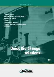
EAS <strong>Quick</strong> Mould Change System Reduces Manufacturing Cost<br />
<strong>Quick</strong> Mould Changes Systems lower manufacturing cost by reducing<br />
<strong>change</strong> over time. Frequent <strong>mould</strong> <strong>change</strong>s allow inventory to be reduced<br />
and provide faster response to customer requirements.<br />
EAS provides the following<br />
QMC solutions:<br />
� Clamping<br />
� Multi-Couplers<br />
� Ejector Couplers<br />
� Mould Handling<br />
� Pre-heating<br />
Resulting in lower manufacturing cost for you…<br />
Step-by-step Automation<br />
QMC Solutions can be applied in<br />
a series of cost effective steps.<br />
First you will need to analyze<br />
the complete <strong>mould</strong> <strong>change</strong><br />
process step by step to identify<br />
where down time losses are<br />
occurring. Moulds that are used<br />
most frequently are your best<br />
candidates and provide the best<br />
return on investment. These<br />
<strong>mould</strong>s should be dedicated to<br />
a specific machine or group of<br />
machines.<br />
Ask EAS…<br />
With These Solutions<br />
You Can Achieve:<br />
� Increased Machine Productivity<br />
� Reduced Labour Cost<br />
� Inventory Reduction<br />
� Increased Flexibility<br />
� Faster Response<br />
� Improved Safety<br />
This analysis will identify where<br />
you should start applying QMC<br />
solutions.<br />
In most cases, clamping will be<br />
the first step to reducing <strong>mould</strong><br />
<strong>change</strong> time. <strong>Quick</strong> clamping<br />
systems are not only faster, but<br />
also safer, as tool set up people<br />
no longer need to climb into the<br />
machine or under the <strong>mould</strong> to<br />
clamp up.<br />
� For the best solution for your application.<br />
� For a Return on Investment calculation.<br />
� For the complete SMED solutions from<br />
one global source.
EAS oFFERS You ThE MoST<br />
CoMplETE RAngE oF<br />
ClAMpIng SoluTIonS<br />
Content: Chapter:<br />
Clamping systems and ejector systems<br />
Manual and automatic multi couplers<br />
Mould <strong>change</strong> tables and cars<br />
Service units and storage systems<br />
1.1 - 1.9<br />
.1 - .<br />
.1 - .10<br />
4.1 - 4.<br />
1<br />
4
4<br />
1.1<br />
Adaptive manually operated<br />
clamping systems<br />
p. 6-7<br />
1.<br />
Adaptive hydraulic <strong>mould</strong><br />
clamping systems<br />
p. 8-9<br />
1.<br />
Mould <strong>change</strong> options<br />
(vertical)<br />
p. 10-11<br />
1.4<br />
Mould <strong>change</strong> options<br />
(horizontal)<br />
p. 12-13<br />
1.5<br />
Integrated hydraulic <strong>mould</strong><br />
clamping systems EAS Engel<br />
p. 14-15<br />
1.6<br />
Electro permanent magnetic<br />
clamping<br />
p. 16-17<br />
1.7<br />
Ejector couplers<br />
p. 18-19<br />
1.8<br />
Retrofit packages<br />
p. 20-21<br />
1.9<br />
Vertical presses and QMC<br />
p. 22-23
1<br />
Clamping systems and ejector systems<br />
5
6<br />
Adaptive, manually Systemes operated de clamping bridage systems<br />
manuel<br />
Application<br />
examples<br />
Horizontal<br />
<strong>mould</strong> <strong>change</strong>
A SIMplE ADApTIvE MAnuAl<br />
ClAMpIng SoluTIon<br />
Machine side:<br />
A clamping<br />
adapter plate<br />
is mounted on<br />
each platen.<br />
The clamping<br />
adapter plate<br />
is drilled to<br />
fit Europmap<br />
mounting<br />
plattens<br />
A clamping<br />
adapter plate<br />
is mounted<br />
to each SPI<br />
platen<br />
Mould side:<br />
Moulds can be easily fitted with<br />
bayonet centering adapters<br />
A simple adaptive clamping solution<br />
for new or existing injection <strong>mould</strong>ing<br />
machines and other applications.<br />
The manual bayonet clamping systems consists of a clamping<br />
adapter plate that is bolted to each platen using existing Euromap<br />
threaded holes. On the stationary side of the <strong>mould</strong> the existing<br />
locating ring is replaced by one of our bayonet centering adapters.<br />
The moveable side of the <strong>mould</strong> will also require a bayonet<br />
centering adapter. When loading the <strong>mould</strong> into the machine<br />
the stationary side bayonet adapter is pushed into the stationary<br />
clamping plate. The <strong>mould</strong> is located on the machine platen-<br />
locating ring. The <strong>mould</strong> is locked in place by a simple 53 degrees<br />
rotation of the lever. The machine is closed and the process is<br />
repeated on the moving side.<br />
The systems are suitable for <strong>mould</strong>s that weight up to 2 t<br />
and injection <strong>mould</strong>ing or rubber <strong>mould</strong>ing machines up to<br />
250 t capacity.<br />
The clamping adapter plates are 17 or 22 mm thick with centering<br />
ring sizes of 100, 110, 125 and 160 mm. The manual system<br />
does not require <strong>mould</strong> standardization other then mounting of the<br />
bayonet adapter rings. Bayonet adapter rings are also available<br />
for tools with insulating plates.<br />
EAS Manual Clamping Solutions<br />
for SpI platen Standards<br />
Manual clamping solutions are available for<br />
SPI machines with multiple ejector bar holes. These systems<br />
utilize a rack and pinion to rotate the lock ring to clamp the<br />
<strong>mould</strong> in place. The SPI manual clamp systems are equipped<br />
with removable handles. SPI clamping plates have a thickness<br />
of 1" inch. Bayonet adapter rings are available in a variety of<br />
configurations.<br />
� EAS can also supply simple roller systems with manual<br />
clamping for horizontally loading <strong>mould</strong>s.<br />
spi machines euromap machines<br />
7<br />
1.1
8<br />
Adaptive Systemes hydraulic de bridage <strong>mould</strong> hydraulique clamping adaptatif systems<br />
All these cylinders can be ordered for several<br />
backplate heights and mounting screws sizes.
ThE IDEAl SoluTIon<br />
FoR AuToMATED QMC SYSTEMS<br />
hydraulic clamping is<br />
the ideal solution for<br />
more automated QMC<br />
requirements. Suitable for<br />
new or existing injection<br />
<strong>mould</strong>ing machines from 50<br />
to 10,000 tonnes capacity.<br />
A typical quick clamping system consists of<br />
4 or more double acting hydraulic clamps,<br />
which are mounted to both platens. The clamp<br />
plungers are angled at a 5 degrees to provide<br />
a self-locking feature. Pressure does not have<br />
to be maintained for the clamps to remain locked<br />
providing additional safety during the <strong>mould</strong>ing<br />
operation.<br />
EAS offers two series of self-locking wedge<br />
clamps: MOD/WOD/NOD series with the<br />
5 degrees plungers and the WS series, which<br />
uses an internal, wedging feature. Both series<br />
clamp on flat back plates and come equipped<br />
with 2 proximity switches to indicate the clamped<br />
and unclamped positions.<br />
The MOD series is the metric version for use on Euromap<br />
standard machines and feature metric mounting patterns<br />
and BSP oil connections.<br />
The WOD series is the imperial version for use on American<br />
SPI standard machines and feature imperial mounting patterns<br />
and SAE oil connections.<br />
The NOD series is available for the Japanese market<br />
requirements.<br />
The back plates of the <strong>mould</strong>s that are used with these series<br />
of clamps must be standardized because the clamps will be<br />
fixed to the platen. Clamps selection is determined by dividing<br />
the opening force of the machine by the number of clamps.<br />
Example: A machine with an opening force of 800kN (80 t)<br />
would need 4 clamps per platen, each with a 200kN (20 t)<br />
capacity or the MOD/WOD/NOD 2010.<br />
Clamps are available in the following capacities:<br />
15, 30, 60, 110, 200, 400 & 1200kN.<br />
Standard temperature range: 60º C (140º F)<br />
High temperature seals and proximity switches available<br />
on request.<br />
The WS series clamps utilize an internal<br />
wedge system, which<br />
allows a greater tolerance on<br />
the back plate thickness.<br />
Clamps come equipped with 2 proximity switches to indicate<br />
the clamped and unclamped positions. This series of clamp<br />
also requires standardized <strong>mould</strong> back plates.<br />
Clamps are available in the following capacities:<br />
80, 200 & 350 kN.<br />
9<br />
1.<br />
mod/wod/nod series<br />
ws-series
10<br />
Mould <strong>change</strong> options<br />
Vertical load<br />
<strong>mould</strong> <strong>change</strong><br />
solution with<br />
fixed clamps<br />
Vertical load<br />
<strong>mould</strong> <strong>change</strong><br />
solution with,<br />
movable clamps.<br />
Clamps are moved<br />
manually or with<br />
hydraulic cylinders.<br />
Vertical load<br />
and rotate<br />
fixed clamp<br />
solution
vERTICAl loAD<br />
MoulD ChAngE<br />
Clamping on<br />
the fixed side<br />
Manual<br />
movable<br />
clamps<br />
Drop and<br />
rotate solution<br />
with safety<br />
latches<br />
(the <strong>mould</strong> on<br />
this machine<br />
is just for<br />
testing)<br />
vertical load <strong>mould</strong><br />
Slide plates<br />
and <strong>mould</strong><br />
<strong>change</strong> is the most<br />
guides on<br />
common method of<br />
a cylinder<br />
loading <strong>mould</strong>s into<br />
the machine.<br />
For this method the<br />
hydraulic clamps are<br />
positioned vertically between<br />
the tie bars on both platens.<br />
On the fixed platen 4 clamps would be mounted with guides,<br />
slide plates, tie bar protectors and <strong>mould</strong> stop locator.<br />
The <strong>mould</strong> slides in behind the <strong>mould</strong> guides and is positioned<br />
by the <strong>mould</strong> stop locator. The clamps can then be activated<br />
and the <strong>mould</strong> is clamped on the fixed platen. The movable<br />
platen is then closed and the movable platen clamps are then<br />
activated. The <strong>mould</strong> is now securely clamped.<br />
Centering rings are not required when using standardized<br />
back plates.<br />
� Movable clamps<br />
Movable clamps can be used when fully<br />
standardized back plates are not feasible.<br />
MOD/WOD/NOD series clamps can be made movable in<br />
T-slots. This movement can be accomplished manually or<br />
automatically using a pneumatic or hydraulic cylinder.<br />
When done automatically the clamp sensor will determine<br />
if the clamp has reached the back plate. The cylinders<br />
are mounted on long T-nuts for accurate movement in the<br />
T-slots. It will still be necessary to standardize the back plate<br />
thickness at the clamping points as well as the height from<br />
the base to centerline if a <strong>mould</strong> stop locator is used.<br />
� vertical load & Rotate<br />
Large <strong>mould</strong>s are often wider than the tie bar gap but must<br />
be rotated between the tie bars when loaded vertically.<br />
For this requirement the MOD/WOD/NOD clamps are<br />
positioned horizontally between the tie bars.<br />
Support ledges with a centering device position and center<br />
the <strong>mould</strong> accurately.<br />
11<br />
1.<br />
verticla loading
1<br />
options sur les <strong>change</strong>ments Mould <strong>change</strong> de options<br />
moules<br />
Horizontal<br />
load <strong>mould</strong><br />
<strong>change</strong> with<br />
non powered<br />
rollers<br />
Horizontal<br />
load <strong>mould</strong><br />
<strong>change</strong> with<br />
powered<br />
roller transfer
hoRIzonTAl MoulD ChAngE<br />
uTIlIzIng A<br />
MoulD ChAngE CAR oR TAblE<br />
Horizontal<br />
load clamp<br />
system with<br />
multi-couplers<br />
on a 1600 t<br />
machine<br />
Horizontal<br />
loading of<br />
a 40 t <strong>mould</strong><br />
from a <strong>change</strong><br />
table into<br />
a 2500 t<br />
machine.<br />
The system<br />
included<br />
pre-rollers,<br />
centering<br />
cylinders,<br />
MOD 4010<br />
clamps and<br />
multicouplers<br />
Powered roller<br />
system on a<br />
500 t machine<br />
When <strong>mould</strong>s are to be <strong>change</strong>d horizontally,<br />
clamps are positioned horizontally between<br />
the tie bars. The platens are equipped with rollers<br />
that allow the <strong>mould</strong> to roll into the press from a<br />
<strong>mould</strong> changing cart or table.<br />
Pre-rollers are used to support the <strong>mould</strong> between the safety<br />
gate and the edge of the platen. Mould stops accurately<br />
position standardized <strong>mould</strong>s in the machine. Centering<br />
cylinders position the <strong>mould</strong> when back plate length is not<br />
standardized. All systems include <strong>mould</strong> guides on the<br />
stationary platen and safety bars on the moveable platen.<br />
This prevents the <strong>mould</strong> from falling if the clamps are<br />
inadvertently retracted. These solutions require standardized<br />
<strong>mould</strong> back plates<br />
� horizontal loading with powered rollers.<br />
A powered roller system is an alternative<br />
method for transferring the <strong>mould</strong> from<br />
the <strong>change</strong> cart or table into the machine.<br />
It replaces a telescopic push/pull device.<br />
The <strong>mould</strong> <strong>change</strong> cart or table and the stationary platen<br />
are equipped with powered rollers while the moveable<br />
platen has non-powered rollers. The powered rollers allow<br />
the <strong>mould</strong> to be <strong>change</strong>d more quickly than telescopic<br />
push/pull devices. They also allow easy <strong>change</strong> for<br />
machines that are on either side of the cart or table.<br />
1<br />
1.4<br />
horizontal loading
14<br />
Integrated hydraulic Système <strong>mould</strong> clamping de bridage systems hydraulique EAS intégré Engel<br />
Clamping bolt mounted<br />
on the <strong>mould</strong><br />
Horizontal loading solution<br />
with integrated clamping system<br />
Machine side
MounTIng In ThE MAChInE plATEn,<br />
lEAvES ThE plATEn CoMplETElY FREE 1.5<br />
The integrated<br />
system keep<br />
the platens<br />
free<br />
Hydraulic<br />
integrated<br />
clamping<br />
systems with<br />
2 proximity<br />
switches for<br />
clamp position<br />
feedback.<br />
The hydraulic cylinder with the<br />
wedge and the clamping bolt<br />
The integrated hydraulic clamping system<br />
(Engel System) is mounted to the sides of the<br />
platen, leaving the platen face completely free<br />
of obstructions. Depending on machine size the<br />
<strong>mould</strong> is clamped using<br />
, 4 or 8 clamps per platen.<br />
Each <strong>mould</strong> would have the corresponding number of EEB<br />
clamping bolts mounted to each side of the <strong>mould</strong>.<br />
Clamping is achieved when the hydraulic cylinder moves<br />
the wedge on the end of the plunger into the matching<br />
wedge shaped slot in the clamping bolt.<br />
On small injection <strong>mould</strong>ing machines only 2 hydraulic<br />
cylinders per platen are required for clamping. On larger<br />
machines (up to 2500 t), 4 hydraulic clamping cylinders<br />
per platen are required to handle the forces defined by<br />
Euromap 11 and VDMA specifications. On very large<br />
machine 8 hydraulic cylinders are required to insure trouble<br />
free clamping.<br />
Location of the clamping cylinders and clamping bolts must<br />
be standardized, and utilizes the centering ring for final<br />
<strong>mould</strong> location.<br />
The integrated hydraulic system can be applied to any new<br />
machine where the platens can be easily modified to accept<br />
the system. These platen modifications do not make it<br />
applicable for retrofit to existing machines.<br />
No standardization of the <strong>mould</strong> or back plates is required<br />
except for mounting of the clamping bolts. The full platen<br />
area can be used for larger <strong>mould</strong>s.<br />
For horizontal load <strong>mould</strong> <strong>change</strong> the <strong>mould</strong> is moved in over<br />
rollers and uses a <strong>mould</strong> stop for final position.<br />
For horizontal loading the <strong>mould</strong> must be standardized for the<br />
bottom to the centerline for proper alignment.<br />
The closing movement of the machine will push the clamping<br />
bolts into the platens. This movement can also be used<br />
connect the multi-coupler systems.<br />
To pull the clamping bolts out of the platens, the opening of<br />
the machine can be used or additional push cylinders can be<br />
mounted to the machine.<br />
eas engel system<br />
15
16<br />
Electro permanent magnetic clamping<br />
pressmag hp<br />
� Very suitable for larger sizes of<br />
injection <strong>mould</strong>ing machines. (>800T)<br />
� High flux generation, high forces on<br />
smaller <strong>mould</strong>s<br />
� Standard 310 mm( 12.2”) long poles<br />
with resin sealing<br />
� Up to 100° C.(212°F)<br />
� Plate thickness 55 mm(2.16”).<br />
� Non magnetic filling plates outside the<br />
tie bar area with flux concentrating<br />
� 25 kN force per pole<br />
pressmag Sp<br />
� Very suitable for smaller sizes<br />
of injection <strong>mould</strong>ing machines (
EAS pRESSMAg. A ToTAl RAngE<br />
FoR EvERY TEMpERATuRE<br />
AnD ApplICATIon<br />
uK<br />
Ideas come from EAS:<br />
Serving the <strong>Quick</strong> Mould Change (QMC) market for more than<br />
20 years, EAS listened carefully to it’s customers to find better<br />
solutions for, YOUR QMC, JIT and SMED needs.<br />
The primary advantage of the magnetic clamping system is that<br />
it avoids the need for standardized back plates for vertically<br />
loaded <strong>mould</strong>s. EAS has optimized their new range of electro<br />
permanent magnetic clamping solutions which support:<br />
� increased demand for full electric injection <strong>mould</strong>ing<br />
machines<br />
� the need for safe systems with sufficient holding force<br />
� simple extra safety device when required<br />
� smaller reduction in daylight opening<br />
Following the acquisition of the Pressmag “know-how” from<br />
Braillon - the original inventor of the electro magnet - EAS<br />
optimized it’s range of magnetic clamping systems by using<br />
both the benefits of the square pole design and the long pole<br />
design for the right application for you, our customer.<br />
The EAS solutions:<br />
� For small sizes of injection <strong>mould</strong>ing machines (
18<br />
Ejector couplers<br />
Mould mounted<br />
part type MEM<br />
Machine mounted<br />
part type MCE
TIME SAvIng AuToMATIC<br />
EjECToR CouplER SYSTEMS<br />
Ejector plate<br />
and rods on<br />
an injection<br />
<strong>mould</strong>ing<br />
machine<br />
In addition to <strong>mould</strong> clamps, multi-couplers<br />
and <strong>change</strong> systems some <strong>mould</strong>ers require<br />
connection of the ejector system on the machine<br />
to the ejector system on the <strong>mould</strong>. The time<br />
consuming manual connections of the ejectors<br />
can be replaced by a simple automatic coupler<br />
system.<br />
The EAS ejector couplers include a floating design to<br />
accommodate larger misalignment between the ejector<br />
coupler and the male adapter, which is mounted to the<br />
<strong>mould</strong> ejector rod.<br />
Features:<br />
Designed to VDMA 24465 part 5 standards. Hydraulically<br />
operated, single acting design. Life expectancy of 2 x 10(6)<br />
cycles at 50% of specified forces on the ejector coupler. Two<br />
proximity switches to indicate coupled and uncoupled position.<br />
Floating design allows 1mm of misalignment correction.<br />
The ejector couplers can also be operated pneumatically at<br />
reduced forces. Please consult EAS for pneumatic applications.<br />
Available in 20, 50, 100 & 200 kN capacities.<br />
For machines with American SpI platen<br />
configuration EAS has designed SpI ejector<br />
couplers which can be used with the 1" and "<br />
SpI ejector patterns without platen modification.<br />
Available in 1" or 2" diameter sizes the SPI ejector couplers<br />
simply push together, connecting the machine ejector to<br />
the <strong>mould</strong> ejector when the <strong>mould</strong> is loaded. When the<br />
<strong>mould</strong> is to be removed the ejector couplers are hydraulically<br />
pressurized to release. (WCE 10 can also be operated<br />
pneumatically)<br />
Our WCE 52 ejector coupler features an optional proximity<br />
switch to provide a confirmation signal to the machine controls.<br />
Extension rods are available on request and are designed for<br />
the specific machine application. The oil inlet is located on the<br />
end of the adapter rod.<br />
Features:<br />
Sized for 1" and 2" knockout holes in the SPI platen<br />
configuration. Single acting design with hydraulic operation.<br />
Please consult EAS for pneumatic applications.<br />
spi machines euromap machines<br />
19<br />
1.7
0<br />
Ensemble pour machines Retrofit existantes<br />
packages
FoR RETRoFITTIng<br />
ExISTIng MAChInES<br />
Retrofit solution with control unit<br />
and satellite boxes<br />
Retrofitted<br />
machine<br />
When the hydraulic clamps can not be<br />
powered by the machine tool hydraulic system,<br />
an independent pump and valve packages can<br />
be installed to provide the hydraulic power<br />
requirements. These pumps are often used on<br />
retrofit systems.<br />
Another advantage is that when the machine is down, the<br />
<strong>mould</strong> <strong>change</strong> can still take place as the pump unit and<br />
controls are independent of the machine. For the MOD- and<br />
WS -series of clamps, a mobile pump unit can be used for<br />
several machines as hydraulic pressure is not required when<br />
clamped but only at the time of the <strong>mould</strong> <strong>change</strong>. EAS have<br />
experienced installation crews to install these systems.<br />
Control unit pCu-10<br />
This central operating panel has a PLC control, a key switch<br />
and enables you to control all clamping, ejector and if needed<br />
multicoupler functions.<br />
Satellite box Sbl-14 and SbR-14<br />
These boxes collect proximity switch signals from the hydraulic<br />
<strong>mould</strong> clamps. SBR-14 for 4 clamps, SBL-14<br />
for 4 clamps plus the ejector coupler.<br />
EAS offers retrofit QMC packages for existing<br />
injection <strong>mould</strong>ing, compression <strong>mould</strong>ing,<br />
thermal forming machines.<br />
Retrofit packages include:<br />
� Adaptive Clamp Options<br />
� Manual Clamps<br />
� Hydraulic Clamps<br />
� Magnetic Clamps<br />
� Manual Multi-couplers<br />
� Automatic Multi-couplers<br />
� Ejector Couplers<br />
� Hydraulic Valve packages<br />
(when hydraulic clamps are required)<br />
� Hydraulic pump units<br />
(when we can not use machine tool hydraulics)<br />
� PLC System Control Packages<br />
(when machine controls are not utilized)<br />
EAS can also offer installation support<br />
europe<br />
america<br />
1<br />
1.8
presses vertical verticales presses and et QMC<br />
ASK FoR ThE CoMplETE<br />
EAS QDC bRoChuRE<br />
Mould carrier equipped with MOD type clamping<br />
cylinders and <strong>mould</strong> lifters. The <strong>mould</strong> is loaded<br />
by means of a manual <strong>mould</strong> <strong>change</strong> car.<br />
MOD wedge clamps were integrated in a specially<br />
designed ring for this special "Ringwalz"<br />
machine to produce automotive wheel frames.<br />
Due to the self-locking feature of this clamp,<br />
hydraulic pressure is not required after clamping<br />
or during the rotational movement of the ring.
In A QuICK AnD SIMplE WAY 1.9<br />
As well as changing <strong>mould</strong>s quickly on horizontal<br />
injection and die cast machines, EAS can also<br />
<strong>change</strong> <strong>mould</strong>s quickly on all your vertical<br />
injection presses, compression presses, rim<br />
presses, <strong>mould</strong> carriers and other special<br />
application presses. EAS offers complete range<br />
of products and solutions to solve these problems<br />
in quick and simple way.<br />
Mechanical clamps mounted on a special plate with spring loaded <strong>mould</strong> lifters<br />
and an isolating plate as well as a set of pre-rollers make this <strong>mould</strong> <strong>change</strong> on<br />
this Duroplast press a simple job.<br />
The pre-rollers are used for several presses by installing mounting hooks onto<br />
each press and moving the rollers from press to press.<br />
Mould <strong>change</strong> car for 2x25 t <strong>mould</strong>s to suit vertical <strong>mould</strong> carrier. The upperbed<br />
on this car rotates 180 degrees. MOD type clamps are used in the <strong>mould</strong> carrier.<br />
� Self-locking clamps type MOD<br />
� Ledge Clamps type MLC<br />
� T-slot Pull Clamps type MHC<br />
� T-slot Clamps type MTC<br />
� Travelling Die Clamps type TDC<br />
� Adaptive hydraulic<br />
clamps:<br />
� Permanent electric magnetic clamping systems<br />
� Integrated hydraulic<br />
clamps:<br />
� Three Position Swing Clamps type MTR<br />
� Swing Clamps type MSR<br />
� Pull Cylinders type MPR<br />
� The EAS Engel wedge clamps<br />
� Die lifters:<br />
Spring loaded or hydraulic ball or roller die lifters for lifting<br />
and moving <strong>mould</strong>s & dies over the lower bed of the press.<br />
� pre-rollers:<br />
Pre-rollers for simple loading and unloading of<br />
dies & <strong>mould</strong>s in vertical presses.<br />
� Mould & Die<br />
<strong>change</strong> cars<br />
product range
4<br />
.1<br />
Manual multi couplers<br />
p. 26-27<br />
.<br />
Automatic multi couplers<br />
p. 28-29
Manual and automatic multi couplers<br />
5
6<br />
Manual multi couplers<br />
Simple and quick leak-proof<br />
connections of several water,<br />
air, oil and electrical circuits.<br />
EAS can provide you with<br />
a complete range of mono<br />
couplers as well.<br />
ASK FoR ouR EAS<br />
CouplER CATAloguES<br />
EAS Europe B.V.<br />
De Hooge Hoek 19A<br />
3927 GG Renswoude<br />
Holland<br />
Tel.: +31 (318) 477 010<br />
Fax.: +31 (318) 477 020<br />
info@eas<strong>change</strong>systems.com<br />
complete solutions from one source<br />
Mono & Multi<br />
Couplers<br />
<strong>Quick</strong> <strong>mould</strong> <strong>change</strong> systems<br />
Mono couplers<br />
Manual multi couplers<br />
Automatic multi couplers
This is an example of how fluid connections<br />
are often done, resulting in inefficient cooling,<br />
leakage and high scrap rates.<br />
Here is an example of the correct way of<br />
connecting several fluid circuits, without the risk<br />
of leakage or misconnenction. When used in<br />
conjunction with a good water treatment system,<br />
EAS multi couplers will reduce scrap and improve<br />
the quality of your production.<br />
Two standard manual multi couplers with 12<br />
water connections, a special manual multi<br />
coupler with 5 electric connectors for signals and<br />
heating purposes and one special manual multi<br />
coupler for hydraulic core pulling connections are<br />
mounted on these 40 t <strong>mould</strong>s.<br />
The fluid and electrical connections are done<br />
within 3 minutes and without leakage of water or<br />
oil, which keeps the area very clean.<br />
A manual mullti coupler with several electrical<br />
connectors for heating and sensor signals.<br />
A standard 12 connection multi coupler, with size<br />
12 (1/2”) water connections is used for the cooling<br />
circuits. A park station is used for hanging<br />
the manual multi coupler during <strong>mould</strong> <strong>change</strong>.<br />
These multi couplers solutions were implemented<br />
on five 1300 t machines.<br />
The leak-proof EAS manual multi couplers are<br />
available in standard versions with 6 and 1 mono<br />
couplers. A variety of hose connection sizes and<br />
configurations are available for the <strong>mould</strong> half<br />
multi couplers.<br />
These high quality leak-proof water couplers can also be<br />
combined with air, hydraulic and electrical connectors to<br />
provide quick connections for all of the <strong>mould</strong>s utilities.<br />
A simple parking station is provided to hang the machine side<br />
multi coupler during <strong>mould</strong> <strong>change</strong>, avoiding coupler damage.<br />
With these coupler solutions, fluid and electrical connections<br />
can be made in a few minutes while keping the floor and the<br />
system clean.<br />
EAS can also supply a complete range of open<br />
and closed multi couplers which are completeley<br />
inter<strong>change</strong>able with a leading competitive brand.<br />
We can also supply a variety of interchangable<br />
mono couplers some<br />
well known brands.<br />
ConTACT EAS FoR<br />
MoRE DETAIlS.<br />
7<br />
.1
8<br />
Automatic multi couplers<br />
EAS multi couplers include<br />
the following types automatic<br />
couplers;<br />
For vertical loading of <strong>mould</strong>s<br />
Designed for <strong>mould</strong>s with many<br />
connections. With one or two moving<br />
docking cylinders to connect circuits<br />
independently of <strong>mould</strong>s and<br />
machine movements.<br />
For horizontal loading<br />
of <strong>mould</strong>s<br />
Similar to vertical loading except<br />
the mounting of the multi couplers is<br />
at the side of the machine.
SIMplE, lEAK pRooF AnD FAST<br />
ConnECTIon oF All YouR FluID AnD<br />
ElECTRIC ConnECTIonS<br />
This 2700 t injection <strong>mould</strong>ing machines with horizontal<br />
loading, has standardized multi couplers on the movable and<br />
fixed side of the machines. Connections for cooling water,<br />
hydraulics for core pull cylinders and electric for heating and<br />
signals, are automatically connected and disconnected.<br />
This connection takes less then 30 seconds.<br />
All couplers feature the leak proof couplers, keeping floor and<br />
envirement clean.<br />
This multi coupler system for horizontal loading connects<br />
water and electric connections trouble free in less than 20<br />
seconds. Another advantage of these multi couplers is that<br />
misconnections are being made any longer, which reduces<br />
the amount of bad products.<br />
Multi couplers can be used with different EAS<br />
couplers.<br />
Most applications use our leakproof self locking couplers type<br />
CQF and CQM, where the two multi coupler halves are locked<br />
together by each individual mono coupler. These couplers<br />
are available from size 6 to size 37 up to 900 l/min and for<br />
hydraulics up to 200 bar pressure. Special connect under<br />
pressure couplers are also available.<br />
The advantage of self locking couplers:<br />
Self locking couplers contain the separating forces which occur<br />
when pressurized. By containing these separating forces within<br />
the body of the coupler we are able to reduce the stress on the<br />
coupler plate and cylinders.<br />
The other advantage with our CQF/M couplers is that if<br />
the <strong>mould</strong> is not in the machine, each coupler can still be<br />
connected for testing purposes.<br />
Because of the leak proof design we can combine water, air,<br />
hydraulic as well and electric connections into one automatic<br />
multi coupler.<br />
EAS also offers standard VDMA multi couplers. The number,<br />
position and arrangements of energy connections for automatic<br />
changing of injection <strong>mould</strong>s are specified and standardized<br />
according to VDMA 24464 and Euromap.<br />
Large size 37 mono couplers are part of the multi<br />
couplers on this machine to connect leakproof large<br />
cooling lines. This in combination with heating oil<br />
connections and electric connections results in a<br />
total <strong>mould</strong> <strong>change</strong> time of less than 15 minutes in<br />
combination with hydraulic clamping and a vertical<br />
<strong>mould</strong> <strong>change</strong> by means of an overhead crane on this<br />
2300 t machine. Fast, safe and clean.<br />
9<br />
.
0<br />
.1<br />
Manual <strong>mould</strong> handling<br />
systems<br />
p. 32-33<br />
.<br />
Battery driven<br />
Mould <strong>change</strong> cars<br />
p. 34-35<br />
.<br />
Mould <strong>change</strong> tables<br />
p. 36-37<br />
.4<br />
Mould <strong>change</strong> tables for two <strong>mould</strong>s<br />
p. 38-39<br />
.5<br />
Mould <strong>change</strong> tables, positioned<br />
between two presses<br />
p. 40-41<br />
.6<br />
Production cells<br />
p. 42-43<br />
.7<br />
Rail guided <strong>mould</strong> <strong>change</strong> cars<br />
p. 44-45<br />
.8<br />
Air floating <strong>mould</strong> <strong>change</strong> car<br />
p. 46-47<br />
.9<br />
Customized solution<br />
p. 48-49<br />
.10<br />
Pre-heating station<br />
p. 50-51
Mould <strong>change</strong> tables and cars<br />
1
Manual <strong>mould</strong> handling systems
A SIMplE hoRIzonTAl WAY<br />
oF ChAngIng MoulDS<br />
Our manual<br />
<strong>mould</strong> <strong>change</strong><br />
car for one<br />
<strong>mould</strong> of max.<br />
800 kg.<br />
Our manual<br />
<strong>mould</strong> <strong>change</strong><br />
car with<br />
2 x 500 kg<br />
<strong>mould</strong>s.<br />
Transferring the <strong>mould</strong> into the machine can be<br />
done manually or must be powered in depending<br />
on the weight of the <strong>mould</strong>. When the <strong>mould</strong> is<br />
light enough, manual transfer is practical.<br />
EAS offers the following solutions:<br />
A manual car is used to transport the <strong>mould</strong>s from the storage<br />
area directly into the machines. The adjustable height feature<br />
uses a hydraulic hand pump and cylinders to raise and lower<br />
the bed. The car can accommodate one 0,8 t or two 0,5 t<br />
<strong>mould</strong>s. When the car arrives at the machine it is positioned<br />
to allow the existing <strong>mould</strong> to be manually pulled out of the<br />
machine. To support the <strong>mould</strong> between the cart and machine<br />
a set of bridge rollers are manually lowered. Once the <strong>mould</strong><br />
has been removed the car is then positioned to allow the new<br />
<strong>mould</strong> to be manually pushed into the machine. The bridge<br />
rollers are then raised up out the way and <strong>mould</strong> is transported<br />
back to the storage area.<br />
EAS can offer different solutions depending on <strong>mould</strong> size<br />
and space limitations. Cars can be configured for side load or<br />
end load operation depending on the plant layout.<br />
Both configurations speed the <strong>mould</strong> <strong>change</strong> process.<br />
The <strong>mould</strong>s are<br />
pushed and<br />
pulled manually.<br />
.1
4<br />
battery driven <strong>mould</strong> <strong>change</strong> cars
FlExIbIlITY, SpEED AnD<br />
EASY To hAnDlE<br />
1 x 20 t with a combination of electric drive and air cushion<br />
floating for exact positioning in front of the machine, storage<br />
and inspection unit.<br />
2 x 3 t with an electric drive, air cushion positioning, an air<br />
driven push-pull device as well as a pre-heating station to heat<br />
up the <strong>mould</strong> outside the machine.<br />
1 x 7 t with height adjustment but with powered transfer of the<br />
<strong>mould</strong>s over the rollers.<br />
When the <strong>mould</strong>s are too heavy to be transported<br />
manually, a battery powered car with hand controls<br />
can be the solution. These cars can be equipped<br />
with variable height roller decks to accommodate<br />
different size machines and storage system levels.<br />
Manual or powered push-pull mechanisms are available to<br />
transfer the <strong>mould</strong>s in and out of the machine or storage system.<br />
These powered transfer mechanism can be operated electrically<br />
or with air.<br />
Mould locks keep the <strong>mould</strong> from moving on the roller deck<br />
when the car is in motion. These cars handle one or two <strong>mould</strong>s<br />
with a combined weight of 25 t and come equipped a battery<br />
charging system.<br />
A two station <strong>mould</strong> <strong>change</strong> car can complete a <strong>mould</strong> <strong>change</strong><br />
in less then 5 minutes when used with the press mounted<br />
roller and clamp system.<br />
When docking the car to the machine is difficult due to<br />
space limitations, EAS can supply a combination battery<br />
powered drive and air cushion car. For normal transport the<br />
battery drive is used. Once at the machine where space and<br />
maneuverability are a problem, the air cushion system is<br />
connected to the air supply and the car is easily floated into<br />
the exact position for loading.<br />
1 x 2 t with height adjustment and<br />
powered transfer of the <strong>mould</strong>s<br />
1 x 2 t with height adjustment<br />
of 400 -1700 mm and electric<br />
push-pull device.<br />
5<br />
.
6<br />
Mould <strong>change</strong> tables
FoR SMAll AnD lARgE MoulDS<br />
up To 00 Ton WEIghT<br />
On an Italtech 2500 t injection <strong>mould</strong>ing machine EAS delivered the horizontal<br />
hydraulic adaptive clamping systems and a <strong>mould</strong> <strong>change</strong> table for <strong>mould</strong>s of<br />
maximum weight of 40 t. Guides on the table allow the crane driver to easily<br />
position the large <strong>mould</strong> in a simple way on the table. An air driven push-pull<br />
spindle device moves the <strong>mould</strong> in and out the machine. All water, hydraulic and<br />
electric connections are made with manual multi coupler systems.<br />
A Windsor 3000 t injection <strong>mould</strong>ing machine is equipped with an adaptive<br />
horizontal hydraulic clamping system, an ejector coupler, automatic multi couplers<br />
and a <strong>mould</strong> <strong>change</strong> table for one <strong>mould</strong> of maximum weight of 35 t.<br />
The operator controls manually the different steps of the <strong>mould</strong> <strong>change</strong>.<br />
Single station <strong>mould</strong> <strong>change</strong> tables dedicated to<br />
an injection <strong>mould</strong>ing machine. They are used<br />
when horizontal loading is required and <strong>mould</strong>s<br />
are <strong>change</strong>d infrequently or space is not available<br />
for two station <strong>mould</strong> <strong>change</strong> tables (see the next<br />
pages for multi station tables).<br />
These tables can use a manual or powered transfer mechanism<br />
depending on <strong>mould</strong> weight to load and unload the machine.<br />
The powered transfer can be equipped with an automatic<br />
push button control.<br />
When using a single station <strong>change</strong> table you must first pull<br />
the <strong>mould</strong> from the machine and remove it from the table<br />
by overhead crane or fork lift truck. The new <strong>mould</strong> is then<br />
positioned on the table roller deck. The new <strong>mould</strong> is then<br />
pushed into the machine. These tables are used in conjunction<br />
with clamp and roller systems in the press (see page 12 & 13).<br />
The time required to do a complete <strong>mould</strong> <strong>change</strong> is depending<br />
on the size and weight of the <strong>mould</strong>. For example, a 40 t<br />
<strong>mould</strong> could be <strong>change</strong>d in less then 20 minutes.<br />
A table for 1 x 20 t <strong>mould</strong> with on one side the rollers with <strong>mould</strong> guidings, while<br />
on the other rollers <strong>mould</strong>s with different dimensions can be placed.<br />
This table has a fixed operation panel. This table also features two guides<br />
to enable the crane operator to position the <strong>mould</strong> easily on the table.<br />
7<br />
.
8<br />
Mould <strong>change</strong> tables for two <strong>mould</strong>s<br />
Step 1<br />
Step<br />
Step
MoulD ChAngES WIThIn<br />
MInuTES InSTEAD oF houRS<br />
Automatic <strong>mould</strong> <strong>change</strong> table<br />
for two <strong>mould</strong>s<br />
of max. 8 t each.<br />
This 800 t machine is<br />
equipped with hydraulic<br />
clamping system with rollers<br />
and with automatic multi<br />
couplers. A <strong>mould</strong> <strong>change</strong><br />
takes place in less then<br />
4 minutes and this system<br />
had a return of investment of<br />
6 months.<br />
Mould <strong>change</strong> table for two <strong>mould</strong>s of max 2 x 15 t, with an<br />
overhead push-pull device. This table features a pre-heating<br />
station with automatic multi couplers connections and was<br />
placed next to 800 t machine and a 1300 t machine.<br />
This <strong>mould</strong> <strong>change</strong> table , which can handle two 20 t <strong>mould</strong>s,<br />
has been fitted with a pre-heating unit; this allow pre-heating<br />
or the <strong>mould</strong>s outside the machine, so that valuable production<br />
time is not lost by heating the <strong>mould</strong>s while it is in the machine.<br />
Integrated multi couplers ensure automatic connection of all<br />
liquid and power supplies.<br />
Mould <strong>change</strong>s with a two station <strong>mould</strong> <strong>change</strong><br />
table are faster then a single station <strong>mould</strong><br />
<strong>change</strong> table because the <strong>mould</strong> is pre-staged<br />
on the table. Additional time can be saved by<br />
pre-heating the <strong>mould</strong> on the table.<br />
When changing a <strong>mould</strong> the <strong>mould</strong> in the machine is pulled<br />
on the empty station on the table. The table is then shuttled<br />
to position the new for loading. The new <strong>mould</strong> is then pushed<br />
into the machine. EAS provides powered transfer mechanisms<br />
which load from one side of the table or both sides of the table.<br />
Powered roller transfer is also available. This system utilizes<br />
powered rollers on the table and in the press to provide<br />
the fastest method of changing <strong>mould</strong>s.<br />
When <strong>mould</strong> <strong>change</strong> tables are used with 2 presses they<br />
increase your flexibility to run smaller production batches and<br />
reduce inventory. Side load systems increase safety for the<br />
operators because the <strong>mould</strong> is always supported and guided<br />
during the <strong>change</strong>. Mould <strong>change</strong> tables can be equipped with<br />
Programmable Logic Control (PLC) system which allows manual,<br />
semi-automatic or fully automatic operation.<br />
Automatic operation requires interfacing with the machine<br />
controls, and they are most often applied on new machines.<br />
Mould <strong>change</strong> tables are often equipped with a hydraulic<br />
power unit to power table movements as well as clamping,<br />
ejector couplers and multi couplers.<br />
On this 1000 t machine this table for<br />
2 x 10 t <strong>mould</strong>s enables the operator<br />
to <strong>change</strong> <strong>mould</strong>s within 6 minutes.<br />
Each <strong>mould</strong> position features a telescopic push pull device for a fast transfer into<br />
the machine. At the end of each device is a pneumatic <strong>mould</strong> gripper to connect<br />
the push pull device to the <strong>mould</strong> automatically. Each <strong>mould</strong> need to be equipped<br />
with an adapter.<br />
9<br />
.4
40<br />
Mould <strong>change</strong> tables, positioned between two presses
MoulD ChAngE TAblES InCREASE<br />
YouR FlExIbIlITY, SpEED AnD SAFETY<br />
At this application a <strong>mould</strong> <strong>change</strong> table was placed in between two 2700 t<br />
injection <strong>mould</strong>ing machines and is able to carry two 40 ton <strong>mould</strong>s. The <strong>mould</strong>s<br />
are loaded and unloaded on the table by an overhead crane. The table is<br />
equipped with pre-heating multi couplers, allowing the new <strong>mould</strong> to be heated<br />
prior to its movement into the machine, saving hours of unproductive time.<br />
At this application EAS selected an overhead transfer mechanism, which is<br />
mounted over the table and on the two machines. Each <strong>mould</strong> is equipped<br />
with two connection bars, mounted on top of the fixed side of the <strong>mould</strong>.<br />
With this solution a <strong>mould</strong> <strong>change</strong> can be done within 10 minutes.<br />
Note; If no overhead crane is available to load and unload the <strong>mould</strong>s on<br />
the table, the table can be equipped as a rail guided car. This table-car brings<br />
the <strong>mould</strong>s then to storage positions where several <strong>mould</strong>s can be stored.<br />
The <strong>mould</strong>s are equipped with standardized<br />
<strong>mould</strong> backplates. The fluid and electric<br />
connections are well organized and being<br />
connected by automatic multi couplers.<br />
When using a <strong>mould</strong> <strong>change</strong> table betwen two<br />
injection machines you will improve your return<br />
on investment because the table is suporting two<br />
machines instead of one. This provides greater<br />
flexibility and faster <strong>change</strong>over.<br />
EAS has implemented solutions with overhead push/pull devices,<br />
telescopic push/pull devices to load from both sides of the<br />
table as well as powered rollers. Powered rollers provide the<br />
fastest <strong>change</strong>over because you do have wait for the push/pull<br />
device to travel into the machine.<br />
Three 3000 t machines are configured with <strong>mould</strong> <strong>change</strong> tables in between.<br />
These powered roller <strong>mould</strong> <strong>change</strong> tables can transfer a 40 t <strong>mould</strong> into either<br />
machine at the push of a button. This provides speed and flexibility to the<br />
<strong>mould</strong>ing process.<br />
EAS equipped the machines with powered rollers and clamping systems.<br />
EAS installed the complete system including platforms, stairs and <strong>mould</strong> <strong>change</strong><br />
table control systems. The operator has acces to the top of the table form the<br />
platforms. Safety gates prevent people from walking on the table during the<br />
<strong>mould</strong> <strong>change</strong>s.<br />
41<br />
.5
4<br />
production cells
FoR YouR CoMplETE<br />
AuToMATED pRoDuCTIon<br />
A fully automatic production cell with pre-heating station working with a 250 t<br />
injection <strong>mould</strong>ing machine.<br />
A 150 t machine with a 2 way 3 position <strong>mould</strong> <strong>change</strong> table, pre-heating,<br />
multi couplers, hydraulic adaptive clamping and an ejector coupler.<br />
The pre-heating equipment is stored under the table and can be easily reached.<br />
Completely automated production cells can<br />
run very smal batches before changing over for<br />
the next run. These , or 4 station <strong>change</strong><br />
tables include pre-heating features and <strong>change</strong><br />
<strong>mould</strong>s automatically.<br />
The <strong>mould</strong>s can be loaded onto the table by overhead<br />
crane or fork lift truck by opening the safety gate.<br />
The EAS production cells consist of clamping systems,<br />
ejector couplers and multi couplers on the machine and<br />
the multiple station <strong>mould</strong> <strong>change</strong> table with pre-heating<br />
system, all operated by PLC controls and on board<br />
hydraulic sytem.<br />
EAS can also provide standardized <strong>mould</strong> back plates,<br />
<strong>mould</strong> side ejector coupler adapters and multi couplers.<br />
In most applications we work closely with the machine<br />
manufacturer to interface cell controls with the machine<br />
controls.<br />
4<br />
.6
44<br />
Rail guided <strong>mould</strong> <strong>change</strong> cars<br />
Mould <strong>change</strong> car travels<br />
within rows of machines<br />
and storage systems and<br />
pre-heating stations,<br />
changing to both sides<br />
of the car.<br />
Mould <strong>change</strong> car<br />
to pick up <strong>mould</strong>s<br />
from the storage<br />
and to bring to one<br />
or more machines.
QuICK, SAFE AnD SIMplE<br />
FoR MoulDS up To 00 Ton<br />
2 x 20 t car with height adjustment<br />
2 x 40 t car in between 7 machines<br />
A further step towards automation is the<br />
installation of a rail car system to serve one<br />
or more injection <strong>mould</strong>ing machines in a<br />
complete line of machines.<br />
This usually means a complete reorganization of the plant<br />
and is most often done at new plants. The <strong>mould</strong> <strong>change</strong><br />
car transports the <strong>mould</strong>s to and from the storage and or<br />
pre-heating stations. Unlike the <strong>mould</strong> <strong>change</strong> tables,<br />
the cars are not equipped to activate the requisite clamping<br />
and energy coupling operations. The cars can be battery<br />
powered or by an overhead power rail or by a cable trolley;<br />
in most cases the option is determined by the rail length<br />
and the normal frequency of <strong>mould</strong> <strong>change</strong>overs.<br />
The cars are equipped with positioning devices for exact<br />
positioning along the machine or at the storage rack.<br />
They can be equipped by a manual or an automatic<br />
connection for the machine interface. The <strong>mould</strong> <strong>change</strong><br />
device can load one side of the car or to both sides of the<br />
car in case the car travels in between rows of machines.<br />
Economy versions are equipped with spindle push/pull<br />
devices. More advanced cars are equipped with telescopic<br />
push/pull devices with automatic <strong>mould</strong> grippers.<br />
For safety purposes, each <strong>mould</strong> roller bed is equipped with<br />
a <strong>mould</strong> lock, which holds the <strong>mould</strong> on the car during<br />
transport along the machines. Safety bumpers, acoustic<br />
or light signals can be part of the car. The cars can be<br />
operated manually, semi automatic or completely automatic.<br />
The operator can either walk along with the cars or drive<br />
on the car from an operator platform. For different sizes of<br />
machines the car can be equipped with height adjustment.<br />
Loading and unloading of the <strong>mould</strong>s can be done from<br />
the storage systems or by an overhead crane. The storage<br />
systems can also be loaded by an overhead crane or by<br />
a fork lift truck.<br />
Mould <strong>change</strong> times for 40 t <strong>mould</strong>s can be accomplished<br />
in 10 minutes with these solutions.<br />
45<br />
.7
46<br />
Air floating <strong>mould</strong> <strong>change</strong> cars "System Aerogo”<br />
Air floating cars actually<br />
float on air film like a<br />
hovercraft and are therefor<br />
very flexible in moving<br />
around pillars or in restricted<br />
areas and can carry very<br />
heavy loads.
EASY MovEMEnTS oF hEAvY loADS .8<br />
A 110 t <strong>mould</strong> is transported from its storage system to the injection <strong>mould</strong>ing<br />
machine or inspection unit. This customer, a producer of large plastic container,<br />
had no overhead crane available for such heavy weights and this solution enables<br />
them to <strong>change</strong> these <strong>mould</strong>s within 35 minutes. The push pull mechanism is<br />
a simple spindle device, which pushes or pulls the <strong>mould</strong>s in or out the large<br />
twin machine.<br />
Space is very limited around the machines at this automotive supplier, two air<br />
floating cars for 2 x 20 and 2 x 15 t <strong>mould</strong>s are used to <strong>change</strong> these <strong>mould</strong>s in<br />
less then 15 minutes. The push /pull changing device can <strong>change</strong> the <strong>mould</strong>s to<br />
both sides of the car, which brings even more flexibility and speed.<br />
For extreme heavy <strong>mould</strong>s as at this container manufacturer EAS installed<br />
this air floating system in combination with storage systems, a 3400 t and<br />
a 6000 t injection <strong>mould</strong>ing machine as well as an EAS inspection unit.<br />
The car can handle up to 150 t <strong>mould</strong>s and the <strong>change</strong> over time is less<br />
then 30 minutes.<br />
Air floating cars actually float on a thin film of air<br />
like a hovercraft whih provides great mobility in<br />
restricted areas. They can also carry very heavy<br />
loads without special floor reinforcement.<br />
An air floating car can be in interesting alternative to rail guided<br />
<strong>mould</strong> <strong>change</strong> cars. They easily move very have loads (up<br />
to 200 tons or more) in tight spaces while providing greater<br />
flexibility in plant layout then a rail system. The floor must have<br />
the cracks filled, be sealed, and level for the best performance.<br />
A suitable air compressor is required with an appropriately sized<br />
air hose. For greater range without several connections points,<br />
an air compressor can be placed on board the car. Noise level<br />
is surprisingly low.<br />
The upper roller deck is the same as a rail guided cart and<br />
features the same style of transfer devices, guides and <strong>mould</strong><br />
locks. They can be loaded from a <strong>mould</strong> storage rack or by<br />
overhead crane.<br />
Air floating cars can be easily positioned in front of the machines<br />
with docking rails and locked to the machine. They can be<br />
controlled by a pendant control panel or by radio control.<br />
Air powered drive wheels control the speed and direction of<br />
the cart while the cart is moving.<br />
Air floating solutions can be very attractive for smaller <strong>mould</strong> handling<br />
requirements. It can also be combined with an electric drive system to travel<br />
longer distance. The operator can walk behind or even sit on board.<br />
Contact EAS for very creative solutions to your <strong>mould</strong> handling problems.<br />
47
48<br />
Customized solutions
EASY MovEMEnTS oF hEAvY loADS .9<br />
For a range of vertical <strong>mould</strong> carriers, producing different internal part for a<br />
well-known car manufacturer in Germany, the space in front of the <strong>mould</strong> carrier<br />
was very limited. A special designed electric driven car on rails was developed<br />
to overcome these difficulties.<br />
The car can carry two <strong>mould</strong>s of each 20 t and the upper bed can turn<br />
180 degrees. The <strong>mould</strong> sequence is therefor as follows; the car arrives with<br />
the new <strong>mould</strong> on the car, it docks on at the press. The existing <strong>mould</strong> is pulled<br />
from the machine onto the car, then unlocks and drives back two meters where<br />
the upper bed is turned 180 degrees. The new <strong>mould</strong> is now brought to and into<br />
the machine with a total <strong>mould</strong> <strong>change</strong> time of 10 minutes.<br />
A well-known Italian car manufacturer developed a very special injection<br />
<strong>mould</strong>ing machine to produce car bumpers. The requirements were; faster,<br />
more flexible, reduce labor cost, reduce energy consumption, reduce floor<br />
space and optimize the production process control by automation.<br />
The <strong>mould</strong> <strong>change</strong> cars are having the following features;<br />
� two way two direction travel with one guiding rail<br />
� a 65 t load bearing capacity<br />
� A floating upper bed table permitting easy self centering<br />
of the <strong>mould</strong> with the upper platen<br />
� Compact size<br />
� Control by means of a remote push button station<br />
� A floor installed carriage guiders, mono rails and side tracks with<br />
crossing for two way movement<br />
� Change over time for 1 <strong>mould</strong> in less then 10 minutes<br />
Special presses or other unusual circumstances<br />
lead sometimes to inventive solutions by EAS as<br />
the picture on page 48 shows.<br />
Because no overhead crane is available at every machine<br />
EAS designed this electric driven car to lift and lower <strong>mould</strong>s<br />
up to 2 t over and in the injection <strong>mould</strong>ing machine.<br />
The vertical lifting stroke is 3000 mm and the horizontal stroke<br />
is 1500 mm.<br />
Ask EAS for your applications.<br />
EAS developed together with Krauss Maffei in Germany a very fast moving<br />
<strong>mould</strong> transport table. Due to the manufacturing method the 6 t <strong>mould</strong> needed<br />
to be moved over a distance of 3000 mm in less then 5 seconds. This short<br />
timeframe is including acceleration and deceleration of the heavy <strong>mould</strong> and<br />
<strong>mould</strong> bed. EAS found the solution with the help of air cushions, normally used<br />
on our aircushion <strong>mould</strong> <strong>change</strong> cars, but now used to float the <strong>mould</strong> bed and<br />
the <strong>mould</strong> over the smooth and flat table frame.<br />
49
50<br />
pre-heating stations
SAvE houRS on YouR ExpEnSIvE<br />
pRoDuCTIon MAChInES<br />
This separate <strong>mould</strong> pre-heating station is used to preheat 20 to 40 t <strong>mould</strong>s<br />
out side the press.<br />
Integrated pre-heating station on a <strong>mould</strong> <strong>change</strong> table with automatic multi<br />
couplers equipped with leak proof hot oil couplers and electric connections.<br />
Electric and hot oil<br />
connections<br />
for pre-heating<br />
the <strong>mould</strong>.<br />
In addition to the use of time saving automatic<br />
clamping and multi coupler systems, pre-heating<br />
<strong>mould</strong>s outside the machine can drastically<br />
reduce <strong>mould</strong> <strong>change</strong> over down time. once<br />
clamped in position, with the energy circuits<br />
connected, a preheated <strong>mould</strong> is ready for instant<br />
production.<br />
This pre-heating can be done by a separate pre-heating<br />
station or by integrated pre-heating on the <strong>mould</strong> <strong>change</strong> car<br />
or table. Dependant on the degree of automation involved,<br />
such a station can be equipped with manual or automatic multi<br />
couplers and the requisite temperature controllers.<br />
51<br />
.10
5<br />
4.1<br />
Inspection units<br />
p. 54-55<br />
4.<br />
Mould turning units<br />
p. 56-57<br />
4.<br />
Storage rack systems<br />
for <strong>mould</strong>s & dies<br />
EAS Lift<br />
p. 58-59
4<br />
Service units and storage systems<br />
5
54<br />
Inspection units<br />
For <strong>mould</strong>s up to t EAS<br />
offers the optim 5 service<br />
units<br />
The standard units are all 1200 mm<br />
long, 580 mm wide and 275 mm<br />
high. The two turning platforms are<br />
350 x 500 mm. Optionally the units<br />
can be placed on a higher table for<br />
easier access or if you have other<br />
requirements such as clamping<br />
solutions, you can discuss these<br />
with your EAS partner.
SIMplE AnD SAFE MAInTEnAnCE<br />
oF YouR ExpEnSIvE ToolS<br />
A German supplier of washing machines uses this inspection<br />
unit with two tilting platerns for 20 t <strong>mould</strong>s. The loading and<br />
unloading of the <strong>mould</strong>s is done by an electric driven and air<br />
floating <strong>mould</strong> <strong>change</strong> car. The unit can also simulate core<br />
pulling movements and ejector couplers movements.<br />
For a well known German manufacturer of plastic containers<br />
EAS equipped several large injection <strong>mould</strong>ing machines up<br />
to 6000 t with an adaptive hydraulic clamping systems, an air<br />
cushion <strong>mould</strong> <strong>change</strong> car, several <strong>mould</strong> storage racks and<br />
an inspection unit for <strong>mould</strong>s up to 100 t.<br />
A small unit for <strong>mould</strong>s of 2 t and with tilting platen.<br />
The control panel can be move around the unit by the operator.<br />
Safety mirrors as well as safety mat are also installed on this unit.<br />
A further stage in the automation of your injection<br />
<strong>mould</strong>ing plant is the installation of an inspection<br />
unit. This rationalizes the inspection and servicing<br />
of <strong>mould</strong>s, superceding a variety of slow and<br />
sometimes hazardous methods involving jacks<br />
and levers or block-and-tackle. Equipped with<br />
hydraulic or magnetic clamping systems on fixed<br />
and movable plates, the inspection unit greatly<br />
facilitates the rotation and precise positioning of<br />
<strong>mould</strong>s for maintenance and repair work; either as<br />
separate halves or coupled tools.<br />
EAS supplies these units in several sizes up to 200 t <strong>mould</strong><br />
weight. The units can be equipped with hydraulic cylinders to<br />
tilt one or two mounting plates 90 degrees.<br />
For safety reasons the units can be equipped with a safety mat,<br />
which stops all movements if somebody steps into the table<br />
and or with safety light curtains which also stops any movement<br />
if somebody comes too close to the unit.<br />
The unit can be equipped with a number of options;<br />
� Additional hydraulic or magnetic clamping systems for<br />
automatic vertical or horizontal <strong>mould</strong> loading.<br />
� U-shape backplates in order to be freely accessible<br />
from the back.<br />
� Multi coupler systems, manually or automatically for<br />
preheating purposes and or for controlling and checking<br />
the core pull cylinders.<br />
� Movable upper clamping systems for different sizes of<br />
backplates.<br />
� Ejector coupler with ejector cylinder for simulation of<br />
ejector movements.<br />
� Steps and stairs for better excess.<br />
� Connection for machine control to simulate certain<br />
programs.<br />
� Spotting capability up to 20 t.<br />
For large container production<br />
heavy <strong>mould</strong>s up to 110 t are<br />
being transported by an<br />
air-floating car from the storage<br />
into this inspection unit.<br />
Either the <strong>mould</strong> half or the total<br />
<strong>mould</strong> can be turned on one side<br />
of the unit. The back of the plate<br />
is open, allowing maintenance<br />
and inspection at the back of the<br />
<strong>mould</strong>. Hydraulic core pulling cylinders are actuated in sequence with the opening<br />
stroke. Easy and safe maintenance without a huge overhead crane enables this<br />
customer to deal with transport and maintenance of very large <strong>mould</strong>s, fast and<br />
55<br />
4.1
56<br />
Mould turning units
CoMbInATIon oF A MoulD ChAngE CAR<br />
AnD An InSpECTIon unIT<br />
Mould <strong>change</strong>-inspection car.<br />
Electric driven and hand<br />
controlled.<br />
Max. <strong>mould</strong> weight 1700 kg.<br />
Mould push and pull device<br />
on both sides.<br />
Spring lifting die lifters<br />
in the platen.<br />
EAS can also supply <strong>mould</strong> turning or <strong>mould</strong> manipulators to turn your<br />
expensive <strong>mould</strong>s 90 degrees for transport or storage in a different way.<br />
A special electrically driven <strong>mould</strong> <strong>change</strong> car<br />
for <strong>mould</strong>s up to 1700 kg is also used as an<br />
inspection unit.<br />
The car has also height adjustment from 950 mm towards<br />
1300 mm and has an electric push/pull device to <strong>change</strong><br />
<strong>mould</strong>s on vertical press. The platen on the car is also equipped<br />
with spring loaded <strong>mould</strong> lifters from the EAS QDC program.<br />
Away from the press the <strong>mould</strong> halves can be separated<br />
over a distance of 600 mm and each platen can be turned<br />
90 degrees for maintenance.<br />
This turning unit is for <strong>mould</strong>s up to 20 t and is remote controlled. EAS can supply<br />
these units up to 100 t <strong>mould</strong> weight.<br />
57<br />
4.
58<br />
EAS LIFT<br />
Rack storage and lift systems for <strong>mould</strong>s or dies<br />
hAnD<br />
ConTRollED<br />
pERMAnEnT<br />
MAgnET lIFTERS<br />
The EAS Lift utilizes state of art<br />
technology to make a powerful,<br />
lightweight permanent lifting<br />
magnet. Our exclusive Test<br />
Talon® feature allows an operator<br />
to safely test load feasibility<br />
and a deep “V” notch between<br />
the pole shoes allows greater stability<br />
when lifting round stock.<br />
For details see:<br />
www. easlift.com (with shop)<br />
EAS offer a wide range of <strong>mould</strong> and<br />
die storage systems. These can be<br />
simple roller beds for horizontal<br />
<strong>mould</strong> or die storage systems or<br />
automated tool storage systems for<br />
100 to 200 <strong>mould</strong>s or dies with<br />
several layers. They can be manually<br />
operated or fully automated.<br />
Single entry<br />
Double entry<br />
Superglide
ToolS nEED To bE SToRED<br />
AnD In MAnY CASES<br />
ThIS IS AWAY FRoM ThE MAChInES<br />
These horizontal <strong>mould</strong> storage systems are loaded and unloaded<br />
by means of electric driven <strong>mould</strong> <strong>change</strong> cars, on which<br />
either manual or automatically <strong>mould</strong>s are placed. Underneath<br />
the <strong>mould</strong>s is room for other <strong>mould</strong> related equipment.<br />
Our glide-out racks are easily handled by one person<br />
and are equipped with an automatic locking system<br />
for operational safety. Three versions are available,<br />
the standard single entry, which can be extended up<br />
to 63% in one direction, double entry shelves which can<br />
be extended up to 63% in two directions and to complete<br />
the range, the superglide, a two-stage extending system<br />
which gives 100% access to the shelf area.<br />
It is a modular system and may be added to, or adjusted<br />
as required and consists of a starter bay and extension bays.<br />
Easily reachable with overhead crane.<br />
Automatic systems can also be supplied for up to<br />
200 <strong>mould</strong>s or more. Treat your expensive tools with<br />
great care and store them safely.<br />
If rail guide <strong>mould</strong> <strong>change</strong> cars, air float <strong>mould</strong> <strong>change</strong><br />
cars, electric driven or manual free moving are being used<br />
one car easily load and unload the <strong>mould</strong>s from these<br />
handling systems onto horizontal <strong>mould</strong> storage systems<br />
or pre heating systems. These horizontal storage systems<br />
are equipped with rollers, a <strong>mould</strong> stop and a <strong>mould</strong><br />
locking device and can placed near the machine or in<br />
other parts or the plant. In case of a railguided system the<br />
storage racks can be placed on both sides of the rails.<br />
This electric driven <strong>mould</strong> <strong>change</strong> car for a large vertical press can bring the<br />
<strong>mould</strong>s far away from the press to a special <strong>mould</strong> storage area.<br />
The <strong>mould</strong>s can be stored left and right of the electric driven car.<br />
The driver has a camera and a monitor for exact positioning the car<br />
into the press. Changing and store <strong>mould</strong>s between 10 and 20 t is in this way<br />
simple, fast and safe.<br />
59<br />
4.<br />
vertical storage<br />
rack systems<br />
horizontal storage<br />
rack systems
EAS Addresses Worldwide<br />
USA, Canada Latin America<br />
& Caribbean<br />
EAS Mold & Die Change System Inc.<br />
W134 N4949 Campbell Drive<br />
Menomonee Falls, WI 53051<br />
United States of America<br />
Tel.: +1 262 783 7955<br />
Tel.: +1 800 664 7086<br />
Fax: +1 262 783 9799<br />
E-mail: cliff.drake@eas<strong>change</strong>systems.com<br />
The Netherlands, Belgium<br />
and Luxemburg<br />
EAS Europe B.V.<br />
De Hooge Hoek 19A<br />
3927 GG Renswoude<br />
The Netherlands<br />
kvk: 30173173<br />
Tel.: +31 318 477 010<br />
Fax: +31 318 477 020<br />
E-mail: info@eas<strong>change</strong>systems.com<br />
France, Belgium, Maroc, Tunesia<br />
EAS France<br />
Pressmag engineering office<br />
429, avenue Léonard De Vinci<br />
ZI Alpespace<br />
F 73800 Ste Hélène-du-Lac.<br />
Tel: +33 479650410<br />
Fax: +33 479650686<br />
E-mail: philippe.aubert@<br />
EAS<strong>change</strong>systems.com<br />
Spain<br />
Bereiker<br />
Pol. Ind. de Goiain<br />
San Andrés 1. Pabellón 5<br />
01170 Legutiano (ARABA)<br />
Spain<br />
Tel.: +34 945 465 460<br />
Fax: +34 945 465 461<br />
E-mail: info@bereiker.com<br />
Brazil<br />
HDB Representacoes Ltda.<br />
Rua Martiniano Lemos Leite, 30<br />
Cotia/SP, CEP,06705-110<br />
Tel.: +55 11 4615 4655<br />
Fax: +55 11 4703 3000<br />
Switzerland<br />
Mega-Plast Kunststofftechnik<br />
Rohnenstraße 14<br />
Postfach 20<br />
8835 Feusisberg<br />
Switzerland<br />
Tel.: +41 44 784 5788<br />
Fax: +41 44 784 75 01<br />
E-mail: mega-plast@bluewin.ch<br />
Italy<br />
EAS MED S.r.L.<br />
Vimercate<br />
Tel: +39 335256569<br />
Tel: + 39 3409343820<br />
Fax: +39 039 9719504<br />
E-mail: walter.brambilla@<br />
eas<strong>change</strong>systems.com<br />
E-mail: marcello.brambilla@<br />
eas<strong>change</strong>systems.com<br />
Germany North, Denmark, Poland<br />
EAS Europe B.V.<br />
Klaus Hermann<br />
Röttges Hof 11<br />
45473 Mülheim/Ruhr<br />
Germany<br />
Tel.: +49 208 76720-91<br />
Fax: +49 208 76647-1<br />
Mobil: +49 171 444 7950<br />
E-mail: klaus.hermann@<br />
eas<strong>change</strong>systems.com<br />
Czech Republic, Slovakia<br />
Kuboušek<br />
Kuboušek s.r.o.<br />
Lidická 1937 370 07<br />
Ceské Budojovice<br />
Tel.: +420 386 102 110<br />
Fax: +420 386 351 819<br />
E-mail: info@kubousek.cz<br />
Internet: www.kubousek.cz<br />
Germany South, Austria, Europe<br />
South-East, Central Europe<br />
Croatia, Hungary and Romania<br />
EAS<br />
Weißdornweg 4b<br />
70599 Stuttgart<br />
Germany<br />
Tel.: +49 711 47623-3<br />
Fax: +49 711 47623-43<br />
E-mail: hero.marggrander@<br />
eas<strong>change</strong>systems.com<br />
United Kingdom<br />
EAS<br />
8, Meadow Close<br />
Marshalswick, St. Albans<br />
Herts AL4 9TG<br />
United Kingdom<br />
Tel.: +44 1727 855 758<br />
Fax: +44 1727 842 823<br />
E-mail: Angus_mac@hotmail.com<br />
Korea<br />
Mico Myoungjin Co<br />
173-260, Gajwa-dong, Seo-gu,<br />
Incheon, Korea (Zip.404-811)<br />
Tel.: +82 32 584 2008<br />
Fax.: +82 32 576 3008<br />
E-mail: qdcmico@korea.com<br />
India<br />
Selplast Corporation India<br />
307, Harekrishna Complex<br />
Pritamnagar, Ashram Road<br />
380.006 Ahmedabad<br />
India<br />
Tel.: +91 79 657 9674<br />
Fax: +91 79 657 9271<br />
E-mail: jvdoctor@selplast.com<br />
Sweden<br />
AMO Produkter AB<br />
Kyrkvägen 1<br />
Sollentuna Holm Gård<br />
19272 Sollentuna<br />
Sweden<br />
Tel.: +46 08 626 8045<br />
Fax: +46 08 626 8047<br />
E-mail: bo.jansson@mbox305.swipnet.se<br />
Finland<br />
Eko - Form<br />
Box 83<br />
00381 Helsinki<br />
Finland<br />
Tel.: +358 1 023 92000<br />
Fax: +358 9 560 74620<br />
Australia<br />
Fleming Plastics Equipment<br />
PTY Ltd.<br />
20/32 Roseberry street<br />
P.O.Box 638<br />
Balgowlah NSW 2093<br />
Australia<br />
Tel.: +61 1300 730 736<br />
Fax: +61 1300 730 739<br />
Mob: +61 417 464 966<br />
Internet: www.fleming.net.au<br />
China<br />
Gienkee Plas Centre<br />
1221 HaMi Road ShaiHai P.C. 200335<br />
Shanghai (200041)<br />
P.R. China<br />
Tel.: +86 21 62398170<br />
Fax: +86 21 32100012<br />
e-mail: info@gienkee.com<br />
Norway<br />
Maskin K. Lund AS Storm Martens<br />
Stalfjaera 11<br />
P.O.Box 21 Kalbakken<br />
0901 Oslo<br />
Norway<br />
Tel.: +47 22 900200<br />
Fax: +47 22 900201<br />
e-mail: firmapost@mklsm.no<br />
New Zealand<br />
Machinetech Ltd.<br />
112A Mays Road<br />
Penrose<br />
Auckland<br />
Tel.: +6496330071<br />
Fax: +6496330072<br />
E-mail: info@machinetech.co.nz<br />
Turkey<br />
AKSOY Plastik ve Makine ltd.<br />
Kucukyali is merkezi, girne mahallesi,<br />
irmak sok E blok no 4<br />
Kucukyali-Maltepe 34852, Istanbul-<br />
Turkey<br />
Tel.:+90 216 5188333<br />
Fax:+90 216 5188324<br />
MOBIL:+90 532 2510298<br />
E-mail: info@aksoymakine.com<br />
www.aksoymakine.com<br />
Portugal<br />
AS Lda.<br />
Rua da Paz Nº 19<br />
Bloco B, Marrazes<br />
2400-404 Leiria<br />
Portugal<br />
Tel.: +351 244 854 675<br />
Fax: +351 244 854 733<br />
E-mail: asales@asales.pt<br />
South Africa<br />
Engel<br />
2 Fabriek Street<br />
Strydom Park, Randburg<br />
P.O Box 5459<br />
Weltevreden Park<br />
1715 South Africa<br />
Tel.: +117937011/2/3/4<br />
Fax: +11 7923381<br />
E-mail: pbracke@engelsa.co.za<br />
www.EAS<strong>change</strong>systems.com<br />
www.EASlift.com<br />
info@EAS<strong>change</strong>systems.com<br />
EASA649 © 2007 EAS - Subject to <strong>change</strong> without notice