A Review of Clock Gating Techniques - MIT Publications
A Review of Clock Gating Techniques - MIT Publications
A Review of Clock Gating Techniques - MIT Publications

You also want an ePaper? Increase the reach of your titles
YUMPU automatically turns print PDFs into web optimized ePapers that Google loves.
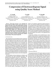
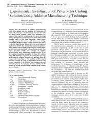
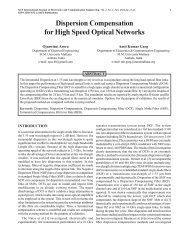
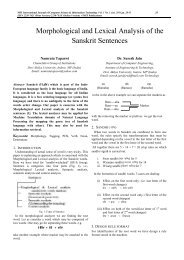
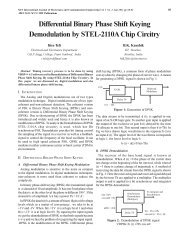
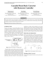
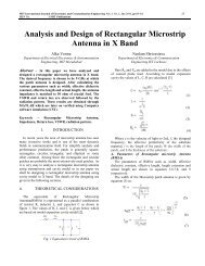
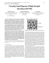
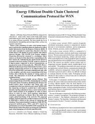
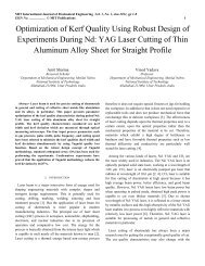
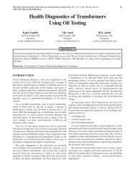
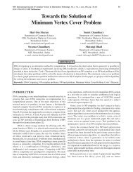
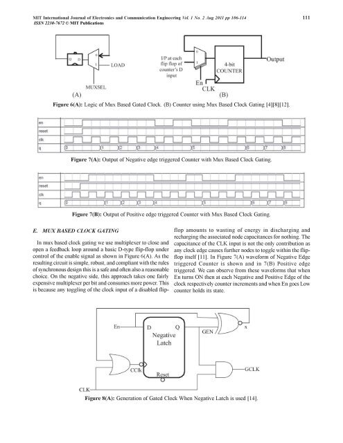
<strong>MIT</strong> International Journal <strong>of</strong> Electronics and Communication Engineering Vol. 1 No. 2 Aug 2011 pp 106-114 111ISSN 2230-7672 © <strong>MIT</strong> <strong>Publications</strong>Figure 6(A): Logic <strong>of</strong> Mux Based Gated <strong>Clock</strong>. (B) Counter using Mux Based <strong>Clock</strong> <strong>Gating</strong> [4][8][12].Figure 7(A): Output <strong>of</strong> Negative edge triggered Counter with Mux Based <strong>Clock</strong> <strong>Gating</strong>.Figure 7(B): Output <strong>of</strong> Positive edge triggered Counter with Mux Based <strong>Clock</strong> <strong>Gating</strong>.E. MUX BASED CLOCK GATINGIn mux based clock gating we use multiplexer to close andopen a feedback loop around a basic D-type flip-flop undercontrol <strong>of</strong> the enable signal as shown in Figure 6(A). As theresulting circuit is simple, robust, and compliant with the rules<strong>of</strong> synchronous design this is a safe and <strong>of</strong>ten also a reasonablechoice. On the negative side, this approach takes one fairlyexpensive multiplexer per bit and consumes more power. Thisis because any toggling <strong>of</strong> the clock input <strong>of</strong> a disabled flipflopamounts to wasting <strong>of</strong> energy in discharging andrecharging the associated node capacitances for nothing. Thecapacitance <strong>of</strong> the CLK input is not the only contribution asany clock edge causes further nodes to toggle within the flipflopitself [11]. In Figure 7(A) waveform <strong>of</strong> Negative Edgetriggered Counter is shown and in 7(B) Positive edgetriggered. We can observe from these waveforms that whenEn turns ON then at each Negative and Positive Edge <strong>of</strong> theclock respectively counter increments and when En goes Lowcounter holds its state.Figure 8(A): Generation <strong>of</strong> Gated <strong>Clock</strong> When Negative Latch is used [14].