peltier concentric cylinder - TA Instruments
peltier concentric cylinder - TA Instruments
peltier concentric cylinder - TA Instruments

Create successful ePaper yourself
Turn your PDF publications into a flip-book with our unique Google optimized e-Paper software.
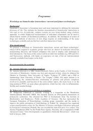
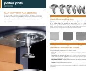
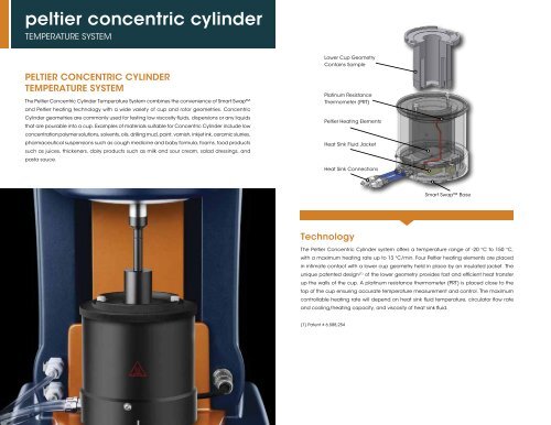
<strong>peltier</strong> <strong>concentric</strong> <strong>cylinder</strong>TEMPERATURE SYSTEMPeltier Concentric CylinderTemperature SystemThe Peltier Concentric Cylinder Temperature System combines the convenience of Smart Swapand Peltier heating technology with a wide variety of cup and rotor geometries. ConcentricCylinder geometries are commonly used for testing low viscosity fluids, dispersions or any liquidsthat are pourable into a cup. Examples of materials suitable for Concentric Cylinder include lowconcentration polymer solutions, solvents, oils, drilling mud, paint, varnish, inkjet ink, ceramic slurries,pharmaceutical suspensions such as cough medicine and baby formula, foams, food productssuch as juices, thickeners, dairy products such as milk and sour cream, salad dressings, andpasta sauce.Lower Cup GeometryContains SamplePlatinum ResistanceThermometer (PRT)Peltier Heating ElementsHeat Sink Fluid JacketHeat Sink ConnectionsSmart Swap BaseTechnologyThe Peltier Concentric Cylinder system offers a temperature range of -20 °C to 150 °C,with a maximum heating rate up to 13 °C/min. Four Peltier heating elements are placedin intimate contact with a lower cup geometry held in place by an insulated jacket. Theunique patented design (1) of the lower geometry provides fast and efficient heat transferup the walls of the cup. A platinum resistance thermometer (PRT) is placed close to thetop of the cup ensuring accurate temperature measurement and control. The maximumcontrollable heating rate will depend on heat sink fluid temperature, circulator flow rateand cooling/heating capacity, and viscosity of heat sink fluid.(1) Patent # 6,588,25414
Cup and Rotor GeometeriesThe standard Peltier Concentric Cylinder geometries include a cup radius of 15 mm, configured with either a Recessed Endor DIN Rotor. Both rotors have a radius of 14 mm and height of 42 mm. The double gap <strong>concentric</strong> <strong>cylinder</strong> has an additionalshearing surface over single gap providing lower stress and higher sensitivity for extremely low viscosity solutions.Special Cups and RotorsSpecialty geometries include various vanes, helical, and starch pasting impeller rotors, as well as large diameter and groovedcups. These special <strong>concentric</strong> <strong>cylinder</strong> geometries are very valuable for characterizing dispersions with limited stability,preventing error from slip at the material/geometry interface, and for bulk materials with larger particulates. Vane geometriesare available in both a 14 mm and 7.5 mm radius. The large diameter cup has a radius of 22 mm. The helical and impeller rotorand cup keep a sample mixed or particles suspended during shearing.Features and Benefits• Unique Smart Swap technology• Wide temperature range: -20 ˚C to 150 ˚C• Peltier temperature control for fast heating and cooling• Popular DIN standard, Recessed End and Double Gap Options• Geometries available in Stainless Steel and Hard• Anodized Aluminum• Wide variety of cup diameters• Impeller and Vane geometries for preventing settling and slipping, and handling of large particles• Pressure Cell• Torsion Immersion• Special geometries available upon requestDouble GapRotor & CupDIN Rotor &Standard CupConcentric Cylinder Cup and Rotor Compatibility ChartStarch PastingImpeller & CupHelical Rotor & CupVane Rotor &Grooved CupCup/Rotor DIN Recessed Starch Vane Wide Gap Double HelicalEnd Impeller Vane Gap RotorStandard (rad= 15 mm)Large Diameter (rad= 22 mm)Starch Diameter (rad= 22 mm)GroovedDouble GapHelicalConcentric Cylinder15
<strong>concentric</strong> <strong>cylinder</strong>ACCESSORIES AND APPLICATIONSGeneric Container HolderThe Generic Container Holder is a Smart Swap option that can hold any container withan outer diameter of up to 80 mm for characterizing materials with rotors. This allows forquick off-the-shelf evaluation of materials, such as paints and varnishes, creams, pastasauce, etc., without creating large shearing from sample loading. It also is an excellentplatform for beakers or jacketed beakers.Flow Curve on Xanthan GumConcentric Cylinder geometries are useful for gathering viscosity flow curve informationover a wide range of shear rates. An example is shown in the figure for a Xanthan Gumsolution. Five decades of viscosity are easily obtained over six decades of shear rate. Thissystem is also a powerful alternative to parallel plate or cone and plate geometries formaterials with limited stability or prone to edge failure or rapid solvent evaporation.Xanthan Gum Solution in Concentric Cylinder100001001000Viscosity (Pa.s)100.010.010.0Shear Stress (Pa)1.00.100.0101.00.0010 0.010 0.10 1.0 10.0 100 1000shear rate (1/s)16
Concentric Cylinder Solvent Trap CoverA Solvent Trap is available for the Peltier Concentric Cylinder. It includes a base reservoir anda two-piece cover that is mounted to the shaft of the rotor. The Solvent Trap provides a vaporbarrier to seal the environment inside the cup and prevents solvent evaporation.Two-Piece CoverBase ReservoirCupRotorFluid in ReservoirSampleCharacterization of Foam with Vane RotorThe figures below show an example of the time and frequency dependent response of a foam shaving cream characterized using a standard cup and vane geometry. The structure of shaving foam has alimited lifetime, or limited stability. The vane geometry minimizes shearing stress that occurs during loading in the gap with standard rotor, keeping the delicate foam structure intact for testing. A wide rangeof structural information can be captured very quickly using multiwave characterization on the DHR. The figure to the left shows a decay in storage modulus G’ as the structure of the foam breaks down withincreasing time. Using the multiwave, the data are simultaneously collected over a wide range of frequencies. The data can be plotted as frequency sweeps at increasing time, as shown on the right. Thesedata show the time dependent viscoelastic response of the shaving foam.Multiwave time sweepFrequency Sweeps on Foam at Different Time Intervals450.01 min20 min40 min60 minG’ (Pa)10 210 3 10 -1 10 0 10 1400.0350.0300.0G’ (Pa)250.0200.0150.0100.050.000f = 0.1 Hzf = 0.2 Hzf = 0.4 Hzf = 0.8 Hzf = 1.6 Hzf = 3.2 Hzf = 6.4 Hzf = 10 Hz0 10.0 20.0 30.0 40.0 50.0 60.0 70.0time (min)f (Hz)Concentric Cylinder17