Lab 4 - Morgan State University
Lab 4 - Morgan State University
Lab 4 - Morgan State University

Create successful ePaper yourself
Turn your PDF publications into a flip-book with our unique Google optimized e-Paper software.
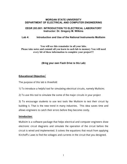
Simulation in MultisimNow that you have electronically "built" the circuit, which is made up of a DCVoltage Source of your own choice in series with five resistors of your ownchoice, you are ready to simulate its operation. The process of building the circuitis what is referred to as "Schematic Capture".Using the simulation capability, you can simulate the circuit's operation by turningthe power switch on and off. Say, for example, that we want to know what is thevoltage across resistors R3 and R4 as seen on the voltmeter. What is the currentin the circuit?Multisim may be used as a tool for verifying results obtained during actuallaboratory work. Circuits may be simulated with the virtual instruments availablein Multisim.We use the instruments by dragging the ones we need to the schematic andhooking them up. We will use the ammeter from the Indicators group and themultimeter as the voltmeter from the Instruments Group.Connect them as follows:Figure 3: Measuring devices added to simple network5
To simulate circuit operation, click on the power switch located in the upper rightcorner. Then double click (click the left mouse button two times quickly) on themulti-meter to show the details of the device, so you can see the reading on themeter as shown below:Figure 4: Examples of voltage and current measurementYou have just completed the Schematic Capture of a circuit and a simulation ofthe circuit operation. Now proceed to the next part where you can Capture andsimulate the preamplifier, detector, FM receiver and amplifier schematics from anAM/FM receiver that will be part of your project at the end of this course.The techniques you have just learned in the first part of this laboratory exercisemay be used to enter and simulate its operation of a wide variety of advancedand more complex networks. For example, consider the schematics for thenetworks shown below, namely the FM Receiver (Figure 5), the amplifier (Figure6), the preamplifier (Figure 7), and the detector (Figure 8).6
Figure 5: FM ReceiverFigure 6: Amplifier7
Figure 7: PreamplifierFigure 8: Detector8
Assignment:Input and simulate the circuits used in <strong>Lab</strong>s 0, 1, 2, and 3, as well as the circuit inthe addendum handed out in class. Compare the results obtained from the actualexperiment to the results obtained using Multisim. Also, simulate the circuits inthe addendum. Compare the input signal against the output signal.For your lab report, include the schematics of the circuits you simulated.Comment on your results. Be quantitative in your comments. Write a shortparagraph on what you learned from this exercise.9