User's Manual - Verizon
User's Manual - Verizon
User's Manual - Verizon

Create successful ePaper yourself
Turn your PDF publications into a flip-book with our unique Google optimized e-Paper software.
Wireless<br />
Broadband<br />
Router<br />
User’s<br />
<strong>Manual</strong><br />
MI424WR
Table of Contents<br />
1 Introduction 1<br />
Package Contents 1<br />
Minimum System Requirements 2<br />
Features 2<br />
Getting to Know the Router 4<br />
2 Connecting the Router 9<br />
Setting Up the Router 9<br />
Computer Network Configuration 11<br />
Configuring the Router 13<br />
Home Page 15<br />
3 Configuring My Network Settings 17<br />
Accessing My Network 17<br />
Using My Network 18<br />
4 Creating a Wireless Network 25<br />
Overview 25<br />
Wireless Status 26<br />
Basic Security Settings 28<br />
Advanced Security Settings 30<br />
Configuring a Wireless Windows XP Client 38<br />
Connecting a Wireless Windows XP Client 40<br />
5 Using Network Connections 45<br />
Network (Home/Office) 46<br />
Ethernet Connection 51<br />
Coax Connection 54<br />
Broadband Ethernet Connection 57<br />
Coax Broadband Connection 62<br />
WAN PPPoE/WAN PPPoE 2 68<br />
6 Configuring the Router’s Security 75<br />
General 77<br />
Access Control 79<br />
Port Forwarding 82<br />
DMZ (Demilitarized Zone) Host 83<br />
Port Triggering 84<br />
Remote Administration 86<br />
Static NAT 88<br />
Advanced Filtering 89<br />
Security Log 92<br />
7 Using Parental Controls 99<br />
Activating Parental Controls 99<br />
Advanced Parental Controls 101<br />
i
Wireless Broadband Router User <strong>Manual</strong><br />
8 Using Advanced Settings 103<br />
Firmware Upgrade 105<br />
Firmware Restore 107<br />
Configuration File 108<br />
System Settings 109<br />
Date and Time 114<br />
Scheduler Rules 115<br />
Routing 117<br />
IP Address Distribution 119<br />
Diagnostics 123<br />
Restoring Default Settings 124<br />
Reboot the Router 124<br />
MAC Cloning 125<br />
ARP (Address Resolution Protocol) Table 125<br />
Users 126<br />
QoS 127<br />
Local Administration 127<br />
Remote Administration 128<br />
Dynamic DNS 128<br />
DNS Server 130<br />
Network Objects 132<br />
Universal Plug and Play (UPnP) 133<br />
Protocols 135<br />
9 Monitoring the Router 137<br />
Router Status 137<br />
Advanced Status 138<br />
10 Troubleshooting 141<br />
A Quality of Service 145<br />
Traffic Priority 145<br />
Traffic Shaping 149<br />
B Specifications 161<br />
General 161<br />
Wireless Operating Range 162<br />
LED Indicators 162<br />
Environmental 162<br />
ii
Introduction<br />
Thank you for purchasing the Wireless Broadband Router. The Wireless<br />
Broadband Router supports Multimedia over Coax Alliance (MoCA), a new networking<br />
standard that allows digital entertainment and information to be transmitted<br />
and distributed to multiple devices over coaxial cables. The Router also supports<br />
Ethernet and Wi-Fi networking, making it the most versatile router available.<br />
If you want to take your home or office networking to the next level, the Wireless<br />
Broadband Router is sure to be one of the keys to your success.<br />
Package Contents<br />
s Wireless Broadband Router<br />
s Black Power cord<br />
s Yellow cable (Ethernet, 6 ft.)<br />
s White cable (Ethernet, 10 ft.)<br />
s Quick Start Guide<br />
s Installation Guide<br />
s User <strong>Manual</strong> CD<br />
s Wireless Networking Guide<br />
1<br />
1
s Wall-mount template<br />
s Vertical stand<br />
s Warranty<br />
Wireless Broadband Router User <strong>Manual</strong><br />
Minimum System Requirements<br />
s Computer with Ethernet capability<br />
s Microsoft Windows 98SE, Me, 2000, or XP; Mac OS 9 or greater; Linux/<br />
BSD, Unix<br />
s Internet Explorer 5.0 or higher; Netscape Navigator 7.0 or higher<br />
s TCP/IP network protocol installed on each computer<br />
Features<br />
s Supports multiple networking standards, including:<br />
WAN - Ethernet and MoCA interfaces<br />
LAN - 802.11g, 802.11b, Ethernet, and MoCA<br />
s Integrated wired networking with 4-port 10/100 Mbps Ethernet switch<br />
and MoCA<br />
s Integrated wireless networking with 802.11g access point featuring:<br />
802.11g enabled to support speeds up to 54 Mbps wirelessly<br />
802.11b backward compatible, communicating with 802.11b wireless<br />
products at speeds up to 11 Mbps<br />
s Enterprise-level security, including :<br />
Fully customizable firewall with Stateful Packet Inspection<br />
Content filtering with URL-keyword based filtering, parental control,<br />
customizable filtering policies per computer, and E-mail notification<br />
Denial of service protection against IP spoofing attacks, intrusion and<br />
scanning attacks, IP fragment overlap, ping of death, and fragmentation<br />
attacks<br />
Event logging<br />
2
Intrusion detection<br />
MAC address filtering<br />
NAT<br />
DMZ hosting<br />
Access control<br />
Chapter 1 Introduction<br />
Advanced wireless protection featuring WPA, WEP 64/128 bit encryption,<br />
802.1x authentication, and MAC address filtering<br />
ICSA certified<br />
s Other Features<br />
DHCP server option<br />
DHCP server/PPPoE server auto-detection<br />
DNS server<br />
LAN IP and WAN IP address selection<br />
MAC address cloning<br />
Port forwarding<br />
PPPoE support<br />
QoS support (end to end layer 2/3) featuring Diffserv, 802.1p/q prioritization,<br />
configurable upstream/downstream traffic shaping, random early<br />
detection and pass-through of WAN-side DSCPs, PHBs, and queuing to<br />
LAN-side devices<br />
Remote management and secured remote management using HTTPS<br />
Reverse NAT<br />
Static NAT<br />
Static routing<br />
Time zone support<br />
VLAN multicast support<br />
VPN IPSec (VPN passthrough only)<br />
3
Getting to Know the Router<br />
Wireless Broadband Router User <strong>Manual</strong><br />
This section contains a quick description of the Router’s lights (LEDs), ports, etc.<br />
The Router features several indicator lights on its front panel, and a series of ports<br />
and switches on its rear panel.<br />
Front Panel<br />
The front panel of the Router features ten indicator lights: Power, WAN Ethernet,<br />
WAN Coax, Internet, LAN Ethernet (4), LAN Coax, and Wireless.<br />
Power Light<br />
The Power light displays the Router’s current status. If the Power light glows<br />
steadily green, the Router is receiving power and fully operational. When the<br />
Power light flashes rapidly, the Router is initializing. If the Power light is not illuminated<br />
or glows red when the Power cord is plugged in and the Power switch is<br />
turned on, the Router has suffered a critical error and technical support should<br />
be contacted.<br />
WAN Ethernet Light<br />
The WAN Ethernet light illuminates when the Router is connected to the<br />
Internet via Ethernet. If flashing, data traffic is passing across the port.<br />
WAN Coax Light<br />
The WAN Coax light glows steadily or flashes when the Router is connected to<br />
the Internet via coaxial cable.<br />
4
Internet Light<br />
Chapter 1 Introduction<br />
When the Internet light glows steadily green, the Router is connected to the ISP<br />
(Internet Service Provider). If it glows amber, there is a physical connection to<br />
the ONT (Optical Network Terminator), but authentication has not taken place<br />
(i.e., no IP address is present).<br />
LAN Ethernet Lights (1, 2, 3, 4)<br />
The LAN Ethernet lights illuminate when the Router is connected to a local<br />
network via one or more of its Ethernet ports. If flashing, data traffic is passing<br />
across the port(s).<br />
LAN Coax Light<br />
The LAN Coax light glows steadily or flashes when the Router is connected to a<br />
local network via its Coax port.<br />
Wireless Light<br />
The Wireless light illuminates when the Router’s wireless access point is turned<br />
on. If flashing, data traffic is passing across the wireless connection.<br />
5
Rear Panel<br />
Wireless Broadband Router User <strong>Manual</strong><br />
The rear panel of the Router features seven ports (Coax, WAN Ethernet, LAN<br />
Ethernet [4], and Power), as well as a Reset button and Power switch.<br />
Coax Port<br />
The Coax port connects the Router to the ISP or other devices using a<br />
coaxial cable.<br />
Reset Button<br />
To restore the Router’s factory default settings, press and hold the Reset button<br />
for approximately ten seconds. The reset process will start about ten seconds<br />
after releasing the button. When the Router resets, all the lights on the front<br />
panel turn off, and then some of the lights start flashing. The Router has completed<br />
its reset process when the Power light glows steadily green.<br />
Caution: Do not unplug the Power cord from the Router dur-<br />
M ing the reset process. Doing so may result in the loss of the<br />
Router’s configuration information. If this occurs, reset the<br />
Router again.<br />
WAN Ethernet Port<br />
The WAN Ethernet port connects the Router to the ISP using an Ethernet cable.<br />
LAN Ethernet Ports (4)<br />
The LAN Ethernet ports connect devices to the Router via Ethernet cables to create<br />
a local area network (LAN). The LAN Ethernet ports are 10/100 Mbps autosensing<br />
ports, and either a straight-through or crossover Ethernet cable can be<br />
used when connecting devices to the ports.<br />
6
Power Switch<br />
Chapter 1 Introduction<br />
The Power switch powers the Router on and off.<br />
Power Port<br />
The Power port connects the Router to an electrical wall outlet via the<br />
Power cord.<br />
7
Wireless Broadband Router User <strong>Manual</strong><br />
This page left intentionally blank.<br />
8
Connecting the<br />
Router<br />
Connecting a computer or local network to the Wireless Broadband Router is a<br />
simple procedure, varying slightly depending on the computer’s operating system<br />
but designed to seamlessly integrate the Router with the computer or local network.<br />
Moreover, addition configuration to access the GUI is not required when taking<br />
advantage of Universal Plug-and-Play support in Windows XP.<br />
The Windows default network settings dictate that in most cases, the setup procedure<br />
described in the “Computer Network Configuration” will be unnecessary.<br />
For example, the default DHCP setting in Windows 2000 is “client,” requiring no<br />
further modification.<br />
However, <strong>Verizon</strong> advises following the setup procedure described below to verify all<br />
communication parameters are valid and the physical cable connections are correct.<br />
Setting Up the Router<br />
There are three parts to setting up the Router: Connecting the Cables, Configuring<br />
the Router, and Connecting Other Computers/Set Top Boxes.<br />
Connecting the Cables<br />
☞<br />
Note: If a different router was being used, disconnect it. Remove<br />
all router components, including power supplies and cables,<br />
since they will not work with the Wireless Broadband Router.<br />
1. Get the Router and black Power cord from the box.<br />
2. Plug the black Power cord in the black port on the back of the Router and<br />
then into a power outlet.<br />
3. Turn the Router on.<br />
4. Make sure the Power light on the front of the Router is glows steadily green.<br />
5. Plug the yellow Ethernet cable from the box into one of the four yellow<br />
Ethernet ports on the back of the Router.<br />
9<br />
2
Wireless Broadband Router User <strong>Manual</strong><br />
6. Make sure the computer is powered on, then plug the other end of the yellow<br />
Ethernet cable into an Ethernet port on the computer.<br />
7. Make sure at least one of the Ethernet LAN lights on the front of the Router<br />
glows steadily green. This may take a few moments.<br />
8. The phone company previously installed a high-speed wall jack somewhere in<br />
the house. Locate it and note its type (Ethernet or coaxial). If Ethernet, follow<br />
steps 8a and 8b. If coaxial, follow steps 9a and 9b. Then, continue to step 10.<br />
a) If connecting via Ethernet, get the white Ethernet cable from the box and<br />
plug one end in the white port on the back of the Router.<br />
b) Plug the other end of the white Ethernet cable into the high-speed<br />
Ethernet jack.<br />
9. a) If connecting via coaxial cable, get a coaxial cable and connect one end to<br />
the red Coax port on the back of the Router.<br />
b) Connect the other end of the coaxial cable to a coax jack.<br />
10. Make sure the Ethernet WAN light (if connecting via Ethernet) or Coax WAN<br />
light (if connecting via coaxial cable) on the front of the Router glows steadily<br />
green. If connecting via coaxial cable, this may take a few minutes.<br />
☞<br />
Note: If the Ethernet WAN light or Coax WAN light does not<br />
illuminate, make sure the cable (Ethernet or coaxial) is connected<br />
properly at both ends.<br />
10
Chapter 2 Connecting the Router<br />
Computer Network Configuration<br />
Each network interface on the computer should either be configured with a statically<br />
defined IP address and DNS address, or instructed to automatically obtain an<br />
IP address using the Network DHCP server. The Router is set up, by default, with an<br />
active DHCP server, and <strong>Verizon</strong> recommends leaving this setting as is.<br />
Configuring Dynamic IP Addressing<br />
To set up a computer to use dynamic IP addressing:<br />
Windows XP<br />
1. Select Network Connections in the Control Panel.<br />
2. Right-click Ethernet Local Area Connection, then click Properties.<br />
3. In the “General” tab, select Internet Protocol (TCP/IP), then click<br />
Properties.<br />
4. The “Internet Protocol (TCP/IP) Properties” window appears.<br />
5. Click the “Obtain an IP address automatically” radio button.<br />
6. Click the “Obtain DNS server address automatically” radio button.<br />
7. Click OK in the “(TCP/IP) Properties” screen, then click OK in the “Local<br />
Area Connection Properties” screen to save the settings.<br />
Windows 2000<br />
1. Select Network and Dialing Connections in the Control Panel.<br />
2. Right-click on the Ethernet connection’s icon, then click Properties.<br />
3. Select Internet Protocol (TCP/IP) component, then click Properties.<br />
4. The “Internet Protocol (TCP/IP) Properties” window appears.<br />
5. Click the “Obtain an IP address automatically” radio button.<br />
6. Click the “Obtain DNS server address automatically” radio button.<br />
11
Windows 98/Me<br />
Wireless Broadband Router User <strong>Manual</strong><br />
1. Select Network in the Control Panel.<br />
2. Select the TCP/IP settings for the network card, then click Properties.<br />
3. Click the “Obtain an IP address automatically” radio button in the “IP<br />
Address” tab.<br />
4. Click Disable DNS in the DNS configuration tab.<br />
5. Click OK in the “TCP/IP Properties” screen.<br />
6. Click OK in the “Network” screen to reboot and save the settings.<br />
Windows NT<br />
1. Click Network in the Control Panel. The “Network” window appears.<br />
2. In the “Protocol” tab, select Internet Protocol (TCP/IP) then click<br />
Properties.<br />
3. In the “IP Address” tab, click the “Obtain an IP address automatically” radio<br />
button.<br />
4. In the “DNS” tab, verify no DNS server is defined in the “DNS Service Search<br />
Order” text box and no suffix is defined in the “Domain Suffix Search<br />
Order” text box.<br />
Linux<br />
1. Login into the system as a super-user, by entering “su” at the prompt.<br />
2. Type “ifconfig” to display the network devices and allocated IPs.<br />
3. Type “pump -i ,” where is the network device name.<br />
4. Type “ifconfig” again to view the newly allocated IP address.<br />
5. Make sure no firewall is active on device .<br />
12
Configuring the Router<br />
Chapter 2 Connecting the Router<br />
1. Open a web browser on the computer connected to the Router. In the<br />
“Address” text box, type:<br />
http://192.168.1.1<br />
then press Enter on the keyboard.<br />
2. The “Login” screen appears. Enter the default user name (admin) and password<br />
(password) in the appropriate text boxes, then click OK.<br />
3. The “Login Setup” screen appears. Select a new user name and password and<br />
enter them in the appropriate text boxes (the password must be entered twice,<br />
for validation purposes). Write the new user name and password down on a<br />
piece of paper and keep it in a safe place, since they will be needed to access<br />
the Router’s MegaControl Panel in the future.<br />
4. In the bottom part of the screen, select the correct time zone from the “Time<br />
Zone” drop-down list, then click OK at the bottom of the screen.<br />
The Router is now configured.<br />
13
Wireless Broadband Router User <strong>Manual</strong><br />
Connecting Other Computers/Set Top Boxes<br />
The Router can connect to other computers or set top boxes in three ways: via<br />
Ethernet, via wireless connection, or via coaxial cable.<br />
Ethernet<br />
1. Get an Ethernet cable and plug one end into one of the open yellow<br />
Ethernet ports on the back of the Router.<br />
2. Plug the other end of the Ethernet cable into an Ethernet port on the computer.<br />
3. Make sure the corresponding Ethernet LAN light on the front of the Router<br />
glows steadily green.<br />
4. Repeat these steps for each computer to be connected to the Router<br />
via Ethernet.<br />
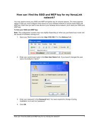
Wireless<br />
1. Make sure each computer to be connected wirelessly has built-in wireless or<br />
an attached wireless adapter.<br />
2. Make sure the computer uses the same ESSID and WEP key as the Router by<br />
launching the computer’s wireless application<br />
3. Enter the ESSID and WEP key found on the sticker on the bottom of the<br />
Router in the computer’s wireless settings and click Save. Make sure to configure<br />
the computer to use 64/40-bit WEP encryption.<br />
4. Make sure the changes were implemented by surfing the Internet from<br />
the computer.<br />
5. Repeat these steps for every other computer to be connected to the<br />
Router wirelessly.<br />
Coaxial<br />
1. Make sure all set top boxes are turned off.<br />
2. Disconnect any adapter currently connected to the coaxial jack in the room<br />
where the Router is.<br />
14
Chapter 2 Connecting the Router<br />
3. Connect one end of the coaxial cable to the coaxial wall jack, and the other<br />
end to the red Coax port on the back of the Router.<br />
4. Power up the set top box.<br />
5. Make sure the Coax LAN light on the front of the Router glows steadily<br />
green. This may take a few minutes. When it does, the set top box is connected<br />
to the Router.<br />
Home Page<br />
After logging into the Router’s MegaControl Panel (see “Configuring the Router” at<br />
the beginning of this chapter), the “Home” screen appears.<br />
The Home screen has a “Main Menu” that occupies the top of the screen. Below<br />
that, the screen is divided into three columns: “My Router,” “My Network,” and<br />
“Action Zone.”<br />
15
Main Menu<br />
Wireless Broadband Router User <strong>Manual</strong><br />
The “Main Menu” contains links to all of the configuration options of the Router:<br />
Wireless Setup (explained in chapter 4 of this manual), My Network (chapter 5),<br />
Firewall (chapter 6), Parental Controls (chapter 7), Advanced (chapter 8), and<br />
System Monitoring (chapter 9).<br />
My Router<br />
This section displays the status of the Router’s network and Internet connection.<br />
A green light signifies the Router is connected; a yellow light means the Router is<br />
attempting to connect; and a red light signifies the Router’s connection is down.<br />
Broadband Connection<br />
The “Broadband Connection” section of My Router displays the state of the<br />
Router’s broadband connection (“Connected” or “Disconnected”) for the two<br />
connection options (“Coax Status” and “Ethernet Status”), and the WAN IP<br />
address of the broadband connection.<br />
Quick Links<br />
The “Quick Links” section of My Router contains a list of frequently accessed<br />
settings, including “Change Wireless Settings,” “Change Login User Name &<br />
Password,” “Enable Gaming,” and “Logout.”<br />
My Network<br />
The “My Network” section of the Home screen displays the connection type, name,<br />
and IP address of all devices connected to the Router’s network. The icon associated<br />
with the device will be displayed normally (signifying an active device) or shaded<br />
(signifying the device has not been active for at least 60 seconds). The user can also<br />
configure the basic settings of each device by clicking on its icon. These settings are<br />
described in more detail in chapter 3, “Configuring My Network Settings.”<br />
Action Zone<br />
This section contains links to various <strong>Verizon</strong> Web sites, and other informational<br />
links. Clicking on the icon above “Go to Internet Now” connects the user to the<br />
home page configured on the user’s web browser.<br />
16
Configuring My<br />
Network Settings<br />
Once the Wireless Broadband Router is physically connected and the MegaControl<br />
Panel’s Home screen is displayed in a web browser, a list of the devices connected<br />
to the Router’s network appears in the “My Network” section of the screen. From<br />
here, some basic network settings can be configured.<br />
Accessing My Network<br />
To access My Network, click on “My Network” in the Home screen.<br />
The “My Network” screen appears:<br />
On the far right side of the screen, in the “Connected Devices” section, is list of the<br />
devices currently connected to the network, listed by connection type and number.<br />
The rest of the screen contains the “My Network” section, which displays each<br />
device connected to the network, and a series of configuration settings.<br />
17<br />
3
Using My Network<br />
Wireless Broadband Router User <strong>Manual</strong><br />
Various settings can be accessed for a particular device, as follows.<br />
Access Device<br />
For devices that can be accessed (such as Internet cameras and networked hard<br />
drives), locate it in the My Network column, then click Access Devices to use the<br />
device over the network.<br />
Access Shared Files<br />
To access the shared files on a particular device, locate the device in the My<br />
Network column, then click Access Shared Files. A list of shared files appears on<br />
the screen.<br />
Website Blocking<br />
Clicking “Website Blocking” generates the “Parental Control” screen. For more<br />
information about using parental controls, see chapter 7, “Using Parental<br />
Controls.”<br />
Block Internet Services<br />
Internet services blocking is used to prevent a device on the network from accessing<br />
particular services on the Internet, such as receiving E-mail or downloading<br />
from FTP sites. To set up Internet services blocking on a networked device, locate<br />
the device in the My Network column, then click Block Internet Services. The<br />
“Access Control” screen appears.<br />
18
Chapter 3 Configuring My Network Settings<br />
1. Click Add in the “Networked computer/Device” column. The “Add Access<br />
Control Rule” screen appears.<br />
2. If this access control rule applies to all networked devices, select “Any” from<br />
the “Networked Computer/Device” list box. If this rule applies to certain<br />
devices only, select “Specify Address” and click Add. Then, add a network<br />
object (for more details about adding network objects, see the “Advanced<br />
Settings” chapter of this manual).<br />
3. Select the Internet protocol to be blocked from the “Protocol” drop-down list.<br />
4. If this rule will be active all the time, select “Always” from the “When should this<br />
rule occur?” drop-down list. If the rule will only be active at certain times select<br />
“Specify Schedule” and click Add. Then, add a schedule rule (for more details<br />
about schedule rules, see the “Advanced Settings” chapter of this manual).<br />
☞ Note:<br />
Make sure the Router’s date and time settings for your time<br />
zone are set correctly for schedule rules to function properly.<br />
5. Click Apply to save the changes. The Access Control screen will display a summary<br />
of the access control rule.<br />
☞ Note:<br />
To block a service that is not included in the list select<br />
“Specify Protocol” from the Protocol drop-down menu. The “Edit<br />
Service” screen appears. Define the service, then click Apply. The<br />
service will then be automatically added to the top section of the<br />
“Add Access Control Rule” screen, and will be selectable.<br />
19
Wireless Broadband Router User <strong>Manual</strong><br />
The user may disable an access control and the service made available without<br />
having to remove the service from the Access Control table. This may be useful to<br />
make the service available only temporarily, with the expectation that the restriction<br />
will be reinstated later.<br />
• To temporarily disable an access control clear the check box next to the network<br />
computer/device.<br />
• To reinstate the restriction at a later time select the check box next to the<br />
network computer/device.<br />
• To remove an access restriction from the Access Control table click the<br />
Remove button for the service. The service will be removed from the Access<br />
Control table.<br />
☞ Note:<br />
When Web Filtering is enabled, HTTP services cannot be<br />
blocked by access control.<br />
Enable Application<br />
Activating “Enable Application” (also known as port forwarding) allows the network<br />
to be exposed to the Internet in certain limited and controlled ways, enabling<br />
some applications to work from the local network (game, voice, and chat applications,<br />
for example), as well as allowing Internet access to servers in the network. To<br />
set this up on a networked device, locate the device in the My Network column,<br />
then click Enable Applications. The “Port Forwarding” screen appears.<br />
20
Chapter 3 Configuring My Network Settings<br />
1. Click Add. The “Add Port Forwarding Rule” screen appears.<br />
2. Enter the local IP address or the host name of the computer providing the service<br />
in the “Networked Computer/Device” text box. Note that only one local<br />
network computer can be assigned to provide a specific service or application.<br />
3. Select the Internet protocol to be provided from the “Protocol” drop-down<br />
list.<br />
4. To select a port to forward communications to (this is optional), select<br />
“Specify” from the “Forward to Port” drop-down list, then, in the text box<br />
that appears, enter the port number. If no port is identified, select “Same as<br />
Incoming Port.”<br />
5. If this port will be active all the time, select “Always” from the “When should this<br />
rule occur?” drop-down list. If the rule will only be active at certain times select<br />
“Specify Schedule” and click Add. Then, add a schedule rule (for more details<br />
about schedule rules, see the “Advanced Settings” chapter of this manual).<br />
6. Click Apply to save the changes.<br />
☞Note: Some applications, such as FTP, TFTP, PPTP, and H323,<br />
require the support of special specific Application Level Gateway<br />
(ALG) modules to work inside the local network. Data packets<br />
associated with these applications contain information that allows<br />
them to be routed correctly. An ALG is needed to handle these<br />
packets and ensure they reach their intended destinations. The<br />
Router is equipped with a robust list of ALG modules, enabling<br />
maximum functionality in the local network.<br />
The ALG is automatically assigned based on the destination port.<br />
21
View Device Details<br />
Wireless Broadband Router User <strong>Manual</strong><br />
To view information about a networked device, or to test a device’s connection,<br />
locate the device in the My Network column, then click View Device Details. The<br />
“Device Information” screen appears.<br />
1. Click Test Connectivity. The “Diagnostics” screen appears.<br />
2. Click Go. The Router runs a ping test, and the results are displayed in the<br />
Diagnostics screen.<br />
22
Rename This Device<br />
Chapter 3 Configuring My Network Settings<br />
To rename a networked device, locate the device in the My Network column, then<br />
click Rename This Device. The “Rename Device” screen appears.<br />
Enter the new name of the device in the “New Name” text box and, if needed,<br />
select a new icon for the device from the “New Icon” drop-down list.<br />
Timeout for Inactive Device<br />
The amount of time a device continues to be displayed on the network after it has<br />
been disconnected is configured in the “Timeout for Inactive Device” screen. To<br />
display the screen, click Timeout for Inactive Device.<br />
Select the timeout period from the “Timeout” drop-down list. After the device has<br />
been disconnected for this amount of time, it will no longer be displayed in the<br />
“My Network” column.<br />
23
Wireless Broadband Router User <strong>Manual</strong><br />
This page left intentionally blank.<br />
24
Creating a Wireless<br />
Network<br />
This chapter explains how to create a wireless network using the Wireless<br />
Broadband Router, including accessing and configuring wireless security options.<br />
Overview<br />
The Wireless Broadband Router provides the user with wireless connectivity over<br />
the 802.11b and g standards (the most common wireless standards). 802.11b has<br />
a maximum data rate of 11 Mbps, while 802.11g has a maximum data rate of 54<br />
Mbps. Both operate in the 2.4 GHz range.<br />
The Router’s wireless feature is turned on, with wireless security activated, by default.<br />
The level of security is 64/40-bit WEP, with a unique WEP key already entered. This<br />
information is displayed on a sticker located on the bottom of the Router.<br />
The Router integrates multiple layers of security. These include the IEEE 802.1x<br />
port-based authentication protocol, RADIUS client, EAP-MD5, EAP-TLS, EAP-TTLS,<br />
EAP-PEAP, Wired Equivalent Privacy (WEP), Wi-Fi Protected Access (WPA) and<br />
firewall and VPN applications.<br />
Connecting a Wireless Client<br />
To connect a wireless client to the Router:<br />
☞ Note: The following procedure assumes the Router’s default wireless<br />
settings are intact. If they have been changed, use the new ESSID<br />
and wireless security settings. For more details, see the “Connecting<br />
a Wireless Windows XP Client” section of this chapter.<br />
1. In the wireless client’s configuration interface, enter the Router’s ESSID<br />
(found on a sticker on the bottom of the Router’s case) in the appropriate<br />
text box or field (this varies depending on the wireless client’s manufacturer).<br />
2. Enter the Router’s WEP key (also found on the sticker on the bottom of the<br />
Router’s case) in the wireless client’s configuration interface.<br />
3. Save the changes and exit the wireless client’s configuration interface. The client<br />
should now detect and join the Router’s wireless network. If not, check the<br />
wireless client’s documentation, or contact its manufacturer.<br />
25<br />
4
Wireless Status<br />
Wireless Broadband Router User <strong>Manual</strong><br />
Clicking on the “Wireless Settings” icon in the Home screen generates the “Wireless<br />
Status” screen, which displays the current status of the wireless connection.<br />
Radio Enabled<br />
Displays whether the Router’s wireless radio is active.<br />
SSID<br />
The SSID (Service Set Identifier) is the network name shared among all devices<br />
on a particular wireless network. The SSID must be identical for all devices on the<br />
wireless network. It is case-sensitive and must not exceed 32 characters. Make sure<br />
the SSID is the same for all devices to be connected to the wireless network. The<br />
Router comes from the factory with an SSID already entered and displayed here.<br />
The default SSID can also be found on a sticker on the bottom of the Router.<br />
Channel<br />
Displays the channel to which the wireless connection is currently set. All devices<br />
on the wireless network must be on the same channel to function correctly.<br />
Security Enabled<br />
Displays what kind of security is active on the wireless connection, and the security<br />
encryption key.<br />
26
SSID Broadcast<br />
Chapter 4 Creating a Wireless Network<br />
Displays whether the Router is broadcasting its SSID. If activated, the SSID of the<br />
Router’s wireless network is broadcast wirelessly.<br />
MAC Authentication<br />
Displays whether the Router is using MAC (Media Access Control) address authentication<br />
to allow wireless devices to join the network.<br />
Wireless Mode<br />
Displays the types of wireless device that can join the network. Options include<br />
802.11b, 802.11g, or Mixed (allows both 802.11b- and 802.11g-equipped wireless<br />
devices to join the network).<br />
Packets Sent/Received<br />
Displays the number of packets sent and received since the Router’s wireless capability<br />
was activated.<br />
27
Basic Security Settings<br />
Wireless Broadband Router User <strong>Manual</strong><br />
To configure the Router’s wireless network for basic security, select “Basic Security<br />
Settings” from the menu on the left side of any Wireless Settings screen. The “Basic<br />
Security Settings” screen appears.<br />
1. Click the “On” radio button to activate the Router’s wireless radio.<br />
2. Enter the name of the wireless network in the “SSID” text box.<br />
3. Select the channel at which the Router’s wireless radio communicates by<br />
selecting it from the “Channel” drop-down list.<br />
4. Click the “WEP” radio button to activate WEP (Wired Equivalent Privacy)<br />
security on the wireless network.<br />
28
Chapter 4 Creating a Wireless Network<br />
5. Select a WEP security level from the “select a WEP Key” drop-down list<br />
(options include “64/40 bit” or “128/104 bit”).<br />
6. Enter the key code in the “Key Code” text box. Each character must be a letter<br />
from A-F or a number from 0-9. If 64/40 bit was selected in step 5, enter 10<br />
characters. If 128/104 was selected, enter 26 characters.<br />
7. Write down the wireless settings displayed on the screen. Other wireless devices<br />
wishing to join the Router’s wireless network must use these same settings<br />
when configuring the device’s wireless networking scheme.<br />
8. Click Apply to save the settings.<br />
29
Advanced Security Settings<br />
Wireless Broadband Router User <strong>Manual</strong><br />
To configure the Router’s advanced wireless network security settings, select<br />
“Advanced Security Settings” from the menu on the left side of any Wireless<br />
Settings screen. The “Advanced Security Settings” screen appears.<br />
☞ Note: The advanced settings should only be configured by experienced<br />
technical users.<br />
Level 1 (Wireless Security)<br />
This section is used to configure different types of wireless security. Select the type<br />
of wireless security to apply to the wireless network by clicking the appropriate<br />
radio button, then configure the security settings in the subsequent screens.<br />
30
WEP<br />
Chapter 4 Creating a Wireless Network<br />
If WEP was selected in the Advanced Security Settings screen, the “WEP Key”<br />
screen appears.<br />
1. Select the appropriate network authentication level from the dropdown<br />
list. Options include Open System Authentication, Shared Key<br />
Authentication, or Both.<br />
2. Activate WEP key 1 by clicking the radio button next to “1” on the left side.<br />
3. Select the length of key 1 by selecting “64/40 bit” or “128/104 bit” from the<br />
appropriate drop-down list in the “Key Length” column.<br />
4. Select the type of key from the appropriate drop-down list in the “Entry<br />
Method” column. If “Hex” is selected, the key must be made up of hexadecimal<br />
digits. If “ASCII” is selected, the key can be made up of any characters.<br />
5. Enter the key in the appropriate text box in the “Encryption Key” column.<br />
If 64/40 bit was chosen in step 2, enter 10 characters. If 128/104 bit was chosen,<br />
enter 24 characters. Depending on what option was selected in step 3,<br />
enter hexadecimal or ASCII characters.<br />
6. Click Apply to save changes.<br />
31
802.1X WEP<br />
Wireless Broadband Router User <strong>Manual</strong><br />
If 802.1X WEP (Wired Equivalent Privacy) was selected, the “WEP+802.1x Radius<br />
Settings” screen appears. To generate the full screen, click in the “Enabled” check<br />
box to activate.<br />
802.1x WEP is a robust security protocol that uses port control with dynamically<br />
changing encryption keys automatically updated over the network. 802.11x WEP<br />
uses a RADIUS (Remote Authentication Dial-in Service) server for authentication<br />
purposes. This server must be physically connected to the Router. Also, the user<br />
must enable the RADIUS client embedded in the Router (to do this, see chapter<br />
9, “Advanced Settings”).<br />
1. Click in the “Enabled” check box to enable WEP+802.1x security.<br />
2. Enter the RADIUS server IP address in the “Server IP” text boxes.<br />
3. Enter the RADIUS server’s port number in the “Server Port” text box.<br />
4. Enter the RADIUS server’s shared secret in the “Shared Secret” text box.<br />
5. Click Apply to save changes.<br />
32
WPA<br />
Chapter 4 Creating a Wireless Network<br />
If WPA (Wi-Fi Protected Access) was selected, the “WPA Key”<br />
screen appears.<br />
1. Verify the authentication method selected is “Pre-Shared Key.”<br />
2. Enter a phrase of at least eight characters in the “Pre-Shared Key” text box.<br />
Verify that “ASCII” is selected in the associated drop-down list.<br />
3. Select the proper encryption algorithm (TKIP or AES).<br />
4. Click in the “Group Key Update Interval” check box to activate the group<br />
key update interval, and set the interval time in the text box to the right.<br />
5. Click Apply at the bottom of the screen to save changes.<br />
33
Level 2 (SSID Broadcast)<br />
Wireless Broadband Router User <strong>Manual</strong><br />
This section is used to configure the Router’s SSID broadcast capabilities.<br />
Selecting “SSID Broadcast” generates the “SSID Broadcast” screen.<br />
Click the “Enable” radio button to enable SSID broadcasting. If enabled, the SSID of<br />
the Router’s wireless network will be broadcast wirelessly. To disable SSID broadcasting,<br />
click the “Disable” radio button.<br />
34
Level 3 (Limiting Access)<br />
Chapter 4 Creating a Wireless Network<br />
This section is used to limit access to the Router’s wireless network.<br />
Wireless MAC Authentication<br />
Wireless MAC authentication allows the user to allow or deny access to the<br />
Router’s wireless network by a particular device’s MAC address. Selecting<br />
“Wireless MAC Authentication” from the Advanced Security Settings screen generates<br />
the “Wireless MAC Authentication” screen.<br />
To set up wireless MAC authentication:<br />
1. Click in the “Enable Access List” check box.<br />
2. Select either “Accept all devices listed below” or “Deny all devices listed<br />
below” by clicking the appropriate radio button. Selecting “Accept…” causes<br />
all devices listed by MAC address to access the Router’s wireless network.<br />
Selecting “Deny…” causes all listed devices to be denied access.<br />
35
Wireless Broadband Router User <strong>Manual</strong><br />
3. Enter the MAC address of a device in the “Client MAC address” text box.<br />
4. Click Add.<br />
5. Repeat steps 3 and 4 to add more devices to the list.<br />
6. When finished listing devices, click Apply.<br />
To remove a MAC address, select it from the “List” list box, then click Remove.<br />
802.11b/g Mode<br />
This option allows the user to select the wireless communication standard compatible<br />
with the devices to be connected on the wireless network from the dropdown<br />
list. Options include 802.11b, 802.11g, or Mixed (allows both 802.11b<br />
and 802.11g-equipped wireless devices to join the network).<br />
Advanced Wireless Options<br />
Clicking “Other Advanced Wireless Options” at the bottom of the Advanced<br />
Security Settings screen generates the “Advanced Wireless Options” screen.<br />
36
When should this rule occur?<br />
Chapter 4 Creating a Wireless Network<br />
Displays the time during which the rule is active. To configure schedule rules, see<br />
chapter 9, “Advanced Settings.”<br />
Network<br />
Select the type of connection being configured from this drop-down list<br />
(options: Network [Home/Office], Broadband Connection, or DMZ).<br />
MTU<br />
MTU (Maximum Transmission Unit) specifies the largest packet size permitted<br />
for Internet transmission. “Automatic” sets the MTU at 1500. Other choices<br />
include “Automatic by DHCP,” which sets the MTU according to the DHCP connection,<br />
and “<strong>Manual</strong>,” which allows the user to set the MTU.<br />
Transmission Rate<br />
Select the wireless transmission rate from the drop-down list, or select “Auto”<br />
to have the Router automatically select the best transmission rate. This setting<br />
adjusts the bit rate of the Router’s wireless transmissions.<br />
CTS Protection Mode<br />
Activating CTS (Clear to Send) Protection Mode allows mixed 802.11b/g networks<br />
to operate at maximum efficiency. Select “Auto” from the drop-down list<br />
to activate. Select “None” to deactivate .<br />
Beacon Interval<br />
Beacons are transmitted by the Router to help identify wireless networks. If beacons<br />
are transmitted too infrequently, networks may become hard to reach; if<br />
too frequently, they become a resource waste. Enter the desired beacon interval<br />
value (in milliseconds) in this text box.<br />
37
DTIM Interval<br />
Wireless Broadband Router User <strong>Manual</strong><br />
Enter the DTIM (Delivery Traffic Indication Message) interval value (in milliseconds)<br />
in this text box. A DTIM is a countdown mechanism for the Router,<br />
informing wireless network clients of the next window for listening to broadcast<br />
and multicast messages.<br />
Fragmentation Threshold<br />
Setting the correct fragmentation threshold can increase the reliability of frame<br />
transmissions on the wireless network. Enter the fragmentation threshold in this<br />
text box.<br />
RTS Threshold<br />
Enter the RTS (Request to Send) threshold in this text box. This setting controls<br />
what size data packet the low level RF protocol issues to an<br />
RTS packet.<br />
Configuring a Wireless Windows XP Client<br />
If the computer has wireless capabilities and is running Windows XP, it will automatically<br />
recognize this and create a wireless connection. View this connection<br />
under Windows’ “Network Connections.”<br />
☞ Note: The following description and images are in accordance<br />
with Microsoft Windows XP, Version 2002, running Service Pack<br />
2. If running another operating system, see the documentation<br />
that came with the wireless adapter being used.<br />
1. Click Network Connections in the Control Panel. The “Network<br />
Connections” window appears.<br />
38
Chapter 4 Creating a Wireless Network<br />
2. Double-click the wireless connection icon. The “Wireless Network<br />
Connection” screen appears, displaying all available wireless networks in the<br />
vicinity. If the Router is connected and active, the Router’s wireless connection<br />
is displayed. Note that the connection’s status is “Not connected” and defined<br />
as “Security-enabled wireless network (WPA)” in the figure below.<br />
3. Click the connection once to mark it, then click Connect at the bottom of the<br />
screen. After the connection is established, its status will change to “Connected.”<br />
An icon appears in the notification area, announcing the successful initiation<br />
of the wireless connection.<br />
4. Test the connection by disabling all other connections in the Network<br />
Connections window and browsing the Internet.<br />
The Router’s wireless network can now be accessed from the configured computer.<br />
However, any other user with a wireless-equipped device can also access the<br />
wireless network. To prevent this, secure the wireless network, as explained in the<br />
“Wireless Security” section of this chapter.<br />
39
Wireless Broadband Router User <strong>Manual</strong><br />
Connecting a Wireless Windows XP Client<br />
This section assumes the Router is set up with WPA security.<br />
1. Click Network Connections in the Control Panel. The “Network<br />
Connections” window appears.<br />
2. Double-click the wireless connection icon. The “Wireless Network<br />
Connection” screen appears, displaying the Router’s wireless connection. Note<br />
that the connection is defined as “Security-enabled wireless network (WPA).”<br />
40
Chapter 4 Creating a Wireless Network<br />
3. Click the connection once to mark it, then click Connect at the bottom of<br />
the screen. The following login window appears, asking for a “Network Key,”<br />
which is the pre-shared key used when configuring the Router’s WPA security<br />
(see the “WPA” section in this chapter).<br />
4. Enter the pre-shared key in both text boxes and click Connect. After the connection<br />
is established, its status will change to “Connected,” as shown below.<br />
An icon appears in the notification area, announcing the successful initiation<br />
of the wireless connection.<br />
5. Test the connection by disabling all other connections in the Network<br />
Connections window and surfing the Internet.<br />
If the login window shown in step 3 does not appear and the connection attempt<br />
fails, configure the connection manually using the following procedure:<br />
1. Click the connection once to mark it and then click Change Advanced<br />
Settings in the “Related Tasks” box on the left part of the window.<br />
41
Wireless Broadband Router User <strong>Manual</strong><br />
2. The “Wireless Network Connection Properties” window appears. Select<br />
Wireless Networks.<br />
3. Click the connection to highlight it, then click Properties. The connection’s<br />
“Properties Window” appears.<br />
4. From the “Network Authentication” drop-down list, select WPA-PSK.<br />
5. From the “Data Encryption” drop-down list, select TKIP.<br />
42
Chapter 4 Creating a Wireless Network<br />
6. Enter the pre-shared key in both the “Network key” and the “Confirm network<br />
key” text boxes.<br />
7. Click OK, then OK again.<br />
8. When attempting to connect to the wireless network, the login window<br />
appears, pre-populated with the pre-shared key. Press Connect to connect.<br />
Since the network is now secured, only users who know the pre-shared key will be<br />
able to connect. The WPA security protocol is similar to securing network access<br />
using a password.<br />
43
Wireless Broadband Router User <strong>Manual</strong><br />
This page left intentionally blank.<br />
44
Using Network<br />
Connections<br />
The Wireless Broadband Router supports various local area network (LAN) and wide<br />
area network (WAN, on Internet) connections via Ethernet or coaxial cables. Network<br />
connections is used to configure the various parameters of the Router’s network and<br />
Internet connections, and create new connections.<br />
Caution: The settings covered in this chapter should be config-<br />
Mured by experienced network technicians only.<br />
To access the Router’s network connections, in the “My Network” screen,<br />
click Network Connections from the menu on the left side. The “Network<br />
Connections” screen appears.<br />
Click Advanced to expand the screen and display all connection entries.<br />
45<br />
5
Wireless Broadband Router User <strong>Manual</strong><br />
To select a connection, click on its name. The rest of this chapter describes the different<br />
network connections available on the Router, as well as the connection types<br />
that can be created.<br />
Network (Home/Office)<br />
Select Network (Home/Office) in the Network Connections screen to generate<br />
the “Network (Home/Office) Properties” screen. This screen displays a list of the<br />
local network’s properties. The only modifications that can be made from this<br />
screen are disabling the connection (by clicking Disable) or renaming the connection<br />
(by entering a new name in the “Rule Name” text box).<br />
☞ Note: When a network is disabled, its formerly underlying<br />
devices will not be able to get the DHCP address from the network<br />
interface to which they were connected.<br />
The Network (Home/Office) connection is used to combine several network<br />
devices under one virtual network. For example, a home/office network can be<br />
created for Ethernet and other network devices.<br />
46
Chapter 5 Using Network Connections<br />
Configuring the Home/Office Network<br />
Click Settings in the “Network (Home/Office) Properties” screen to generate the<br />
“Configure Network (Home/Office)” screen.<br />
General<br />
The top part of the Configure Network (Home/Office) screen displays general<br />
communication parameters. <strong>Verizon</strong> recommends not changing the default values<br />
in this section unless familiar with networking concepts.<br />
Status Displays the connection status of the network.<br />
When should this rule occur? Displays when the rule is active. To schedule rules,<br />
see the “Advanced Settings” chapter.<br />
Network Select the type of connection being configured from the drop-down list<br />
(options: Broadband Connection, Network [Home/Office], or DMZ).<br />
Connection Type Displays the type of connection.<br />
Physical Address Displays the physical address of the network card used for the<br />
network.<br />
MTU MTU (Maximum Transmission Unit) specifies the largest packet size permitted<br />
for Internet transmission. “Automatic” sets the MTU at 1500. Other choices<br />
include “Automatic by DHCP,” which sets the MTU according to the DHCP<br />
connection, and “<strong>Manual</strong>,” which allows the MTU to be set manually.<br />
47
Internet Protocol<br />
Wireless Broadband Router User <strong>Manual</strong><br />
This section has three options: No IP Address, Obtain an IP Address<br />
Automatically, and Use the Following IP Address.<br />
No IP Address Select this option if the connection will have no IP address. This is<br />
useful if the connection operates under a bridge.<br />
Obtain an IP Address Automatically Select this option if the network connection<br />
is required by the ISP to obtain an IP address automatically. The server assigning<br />
the IP address also assigns a subnet mask address, which can be overridden by<br />
entering another subnet mask address.<br />
Use the Following IP Address Select this option if the network connection uses a<br />
permanent (static) IP address, then the IP address and subnet mask address.<br />
Bridge<br />
The “Bridge” section of the Configure Network (Home/Office) screen is used to<br />
specify which networks can join the network bridge.<br />
☞ Note: When a network is disabled, its formerly underlying<br />
devices inherit the network’s DHCP settings. For example, the<br />
removal of a network configured as DHCP client automatically<br />
configures the devices formerly constituting the network as<br />
DHCP clients, with the exact DHCP client configuration.<br />
Click in the check box next to the particular network to specify it. Make sure<br />
there are no loops in the network configuration, and apply these settings in case<br />
the network consists of multiple switches, or other bridges apart from those created<br />
by the Router.<br />
Status The “Status” column displays the connection status of a particular device.<br />
48
Chapter 5 Using Network Connections<br />
STP Click in the device’s “STP” check box to enable Spanning Tree Protocol on<br />
the device. This protocol provides path redundancy while preventing undesirable<br />
loops in the network.<br />
Action The “Action” column contains an icon that, when clicked, generates the<br />
configuration screen of the particular device.<br />
DNS Server<br />
Domain Name System (DNS) is the method by which website or domain names<br />
are translated into IP addresses. Specify such an address manually, according to<br />
the information provided by the ISP.<br />
To manually configure DNS server addresses, select Use the Following DNS<br />
Server Addresses. Specify up to two different DNS server addresses, one primary,<br />
the other secondary.<br />
IP Address Distribution<br />
The “IP Address Distribution” section of the Configure Network (Home/Office)<br />
screen is used to configure the Router’s Dynamic Host Configuration Protocol<br />
(DHCP) server parameters. DHCP automatically assigns IP addresses to network<br />
devices. If enabled, make sure to configure the network devices as “DHCP<br />
Clients.” There are three options in this section: Disabled, DHCP Server, and<br />
DHCP Relay.<br />
Disabled Select this option if statically assigning IP addresses to the network<br />
devices.<br />
DHCP Server To set up the network bridge to function as a DHCP server:<br />
1. Select DHCP Server.<br />
2. Enter the IP address at which the Router starts issuing addresses in the<br />
“Start IP Address” text boxes. Since the Router’s default IP address is<br />
192.168.1.1, the Start IP Address should be 192.168.1.2.<br />
3. Enter the end of the IP address range used to automatically issue IP addresses<br />
in the “End IP Address” text boxes. The “maximum” IP address that can<br />
be entered here is 192.168.1.253.<br />
49
Wireless Broadband Router User <strong>Manual</strong><br />
4. Enter the subnet mask address in the “Subnet Mask” text boxes. The subnet<br />
mask determines which portion of a destination LAN IP address is the network<br />
portion, and which portion is the host portion.<br />
5. If Windows Internet Naming Service (WINS) is being used, enter the WINS<br />
server address in the “WINS Server” text boxes.<br />
6. Enter the amount of time a network device will be allowed to connect to<br />
the Router with its currently issued dynamic IP address in the “Lease Time<br />
in Minutes” text box.<br />
7. Click in the “Provide Host Name If Not Specified by Client” check box to<br />
have the Router automatically assign network devices with a host name, in<br />
case a host name is not provided by the user.<br />
DHCP Relay Select this option to have the Router function as a DHCP relay, and<br />
enter the IP address in the screen that appears.<br />
Routing<br />
The Router can be configured to use static or dynamic routing. Dynamic routing<br />
automatically adjusts how packets travel on the network, while static routing<br />
specifies a fixed routing path to neighboring destinations.<br />
There are two options in the “Routing” section of the Configure Network<br />
(Home/Office) screen: Basic or Advanced.<br />
Basic Select this option for basic routing operation.<br />
Advanced To set up the Router’s network bridge for advanced routing:<br />
1. Select Advanced from the “Routing” drop-down menu.<br />
2. Enter a device metric in the “Device Metric” text box. The device metric is<br />
a value used by the Router to determine whether one route is superior to<br />
another, considering parameters such as bandwidth and delay time.<br />
3. Click in the “Default Route” check box to define this device as a the<br />
default route.<br />
4. Click in the “Multicast - IGMP Proxy Internal” check box to activate<br />
multicasting.<br />
50
Routing Table<br />
Chapter 5 Using Network Connections<br />
Clicking New Route generates the “New Route” window, where a new route can<br />
be configured.<br />
Additional IP Addresses<br />
Clicking New IP Address generates the “Additional IP Address Settings” screen,<br />
where additional IP addresses can be created to access the Router via the<br />
Network (Home/Office) connection.<br />
Ethernet Connection<br />
An Ethernet connection connects computers to the Router using Ethernet cables,<br />
either directly or via network hubs and switches. Click Ethernet in the Network<br />
Connections screen (if needed, click Advanced at the bottom of the screen to<br />
reveal the “Ethernet” link below “Network [Home/Office]”) to generate the<br />
“Ethernet Properties” screen. This screen displays a list of the connection’s properties.<br />
The only modifications that can be made from this screen are disabling the<br />
connection (by clicking Disable) or renaming the connection (by entering a new<br />
name in the “Rule Name” text box).<br />
☞ Note: If disabling the connection, the Router must be rebooted<br />
for the change to take effect.<br />
51
Wireless Broadband Router User <strong>Manual</strong><br />
Configuring the Ethernet Connection<br />
Click Settings at the bottom-right of the Ethernet Properties screen to generate the<br />
“Configure Ethernet” screen.<br />
General<br />
The top part of the Configure Ethernet screen displays general communication<br />
parameters. <strong>Verizon</strong> recommends not changing the default values in this section<br />
unless familiar with networking concepts.<br />
Status Displays the connection status of the Ethernet switch.<br />
When should this rule occur? Displays when the rule is active. To schedule rules,<br />
see the “Advanced Settings” chapter.<br />
Network Select the type of connection being configured from the drop-down list<br />
(Network [Home/Office], Broadband Connection, or DMZ).<br />
Connection Type Displays the type of connection.<br />
Physical Address Displays the physical address of the network card used for<br />
the network.<br />
MTU MTU (Maximum Transmission Unit) specifies the largest packet size permitted<br />
for Internet transmission. “Automatic” sets the MTU at 1500. Other choices<br />
include “Automatic by DHCP,” which sets the MTU according to the DHCP<br />
connection, and “<strong>Manual</strong>,” which allows the MTU to be set manually.<br />
52
Additional IP Addresses<br />
Chapter 5 Using Network Connections<br />
Clicking New IP Address generates the “Additional IP Address Settings” screen,<br />
where additional IP addresses can be created to access the Router via the<br />
Ethernet connection.<br />
4 Ports Ethernet Switch<br />
This section displays the connection status of the Router’s four Ethernet ports.<br />
Clicking on a connection’s “Action” icon (in the column on the right) generates<br />
the “Port VLANs” screen, where ingress and egress policies can be edited.<br />
53
Coax Connection<br />
Wireless Broadband Router User <strong>Manual</strong><br />
A Coax connection connects devices (such as set-top boxes) to the Router using<br />
a coaxial cable. Click Coax in the Network Connections screen (if needed, click<br />
Advanced at the bottom of the screen to reveal the “Coax” link below “Network<br />
[Home/Office]”) to generate the “Coax Properties” screen. This screen displays a<br />
list of the connection’s properties. The only modifications that can be made from<br />
this screen are disabling the connection (by clicking Disable) or renaming the<br />
connection (by entering a new name in the “Name” text box).<br />
☞ Note: If disabling the connection, the Router must be rebooted<br />
for the change to take effect.<br />
54
Configure Coax<br />
Chapter 5 Using Network Connections<br />
Click Settings at the bottom-right of the Coax Properties screen generates the<br />
“Configure Coax” screen.<br />
General<br />
The top part of the Configure Coax screen displays general communication<br />
parameters. <strong>Verizon</strong> recommends not changing the default values in this section<br />
unless familiar with networking concepts.<br />
Status Displays the status of the coax connection.v<br />
When should this rule occur? Displays when the rule is active. To schedule rules,<br />
see the “Advanced Settings” chapter<br />
Network Displays the type of network.<br />
Connection Type Displays the type of connection.<br />
Physical Address Displays the physical address of the network card used for the<br />
network.<br />
MTU MTU (Maximum Transmission Unit) specifies the largest packet size permitted<br />
for Internet transmission. “Automatic” sets the MTU at 1500. Other choices<br />
include “Automatic by DHCP,” which sets the MTU according to the DHCP<br />
connection, and “<strong>Manual</strong>,” which allows the MTU to be set manually.<br />
55
Coax Link<br />
Wireless Broadband Router User <strong>Manual</strong><br />
Set up the coax link options in this section of the Configure Coax screen.<br />
Options include Channel, Privacy, and Password.<br />
Channel Select the Channel from the drop-down list (select from 1-6, or<br />
“Automatic”).<br />
Privacy Toggle “Privacy” by clicking in the “Enabled” check box. If Privacy is<br />
activated, all devices connected via coaxial cable must use the same password.<br />
<strong>Verizon</strong> recommends leaving the Privacy option deactivated.<br />
Password Enter the Coax Link password in this text box.<br />
Additional IP Addresses<br />
Clicking New IP Address generates the “Additional IP Address Settings” screen,<br />
where additional IP addresses can be created to access the Router via the Coax<br />
Link Ethernet connection.<br />
Coax Connection Status<br />
Click Go to LAN Coax Stats to generate the “Coax Connection Status” screen,<br />
which gives an overview of all the devices connected to the Router via coaxial cable.<br />
56
Chapter 5 Using Network Connections<br />
Broadband Ethernet Connection<br />
A Broadband Ethernet connection connects the Router to the Internet using an<br />
Ethernet cable. Click Broadband Connection (Ethernet) from the Network<br />
Connections screen to generate the “Broadband Connection (Ethernet) Properties”<br />
screen. This screen displays a list of the connection’s properties. The only modifications<br />
that can be made from this screen are disabling the connection (by clicking<br />
Disable) or renaming the connection (by entering a new name in the “Rule Name”<br />
text box).<br />
☞ Note: If disabling the connection, the Router must be rebooted<br />
for the change to take effect.<br />
57
Wireless Broadband Router User <strong>Manual</strong><br />
Configuring the Broadband Ethernet Connection<br />
Click Settings at the bottom-right of the Broadband Connection (Ethernet) Properties<br />
window to generate the “Configure Broadband Connection (Ethernet)” screen.<br />
General<br />
The top part of the screen displays general communication parameters. <strong>Verizon</strong><br />
recommends not changing the default values in this section unless familiar with<br />
networking concepts.<br />
Status Displays the status of the Ethernet connection (“Down,” “Connected,”<br />
etc.)<br />
Schedule Displays when the rule is active. To configure rules, see the “Advanced<br />
Settings” chapter.<br />
Network Select the type of connection being configured from the drop-down list<br />
(options: Network (Home/Office), Broadband Connection, or DMZ).<br />
Connection Type Displays the type of connection. Since this is an Ethernet<br />
Connection, “Ethernet” is displayed.<br />
Physical Address Displays the physical address of the network card used for the<br />
network.<br />
58
Chapter 5 Using Network Connections<br />
MTU MTU (Maximum Transmission Unit) specifies the largest packet size permitted<br />
for Internet transmission. “Automatic, sets the MTU at 1500. Other choices<br />
include “Automatic by DHCP,” which sets the MTU according to the DHCP<br />
connection, and “<strong>Manual</strong>,” which allows the MTU to be set manually.<br />
Internet Protocol<br />
This section includes three options: No IP Address, Obtain an IP Address<br />
Automatically, and Use the Following IP Address.<br />
No IP Address Select this option if the connection has no IP address. This is useful<br />
if the connection is operating under a bridge.<br />
Obtain an IP Address Automatically Select this option if the ISP requires the connection<br />
to obtain an IP address automatically. The server assigning the IP address<br />
also assigns a subnet mask address, which can be overridden by clicking in the<br />
“Override Subnet Mask” check box and entering another subnet mask address.<br />
Additionally, the DHCP lease can be renewed and/or released by clicking on the<br />
appropriate “DHCP Lease” button. The “Expires In” value displays how long until<br />
the DHCP lease expires.<br />
Use the Following IP Address Select this option if the connection uses a permanent<br />
(static) IP address. The ISP should provide this address, along with a subnet<br />
mask address, default gateway address, and, optionally, primary and secondary<br />
DNS server addresses.<br />
DNS Server<br />
The Domain Name System (DNS) is the method by which website or domain<br />
names are translated into IP addresses. This connection can be configured to<br />
automatically obtain a DNS server address, or such an address can be specified<br />
manually, according to the information provided by the ISP.<br />
To configure the connection to automatically obtain a DNS server address, select<br />
Obtain DNS Server Address Automatically from the “DNS Server” drop-down<br />
list. To manually configure DNS server addresses, select Use the Following DNS<br />
Server Addresses. Specify up to two different DNS server addresses, one primary,<br />
the other secondary.<br />
59
IP Address Distribution<br />
Wireless Broadband Router User <strong>Manual</strong><br />
The “IP Address Distribution” section of the Configure Broadband Connection<br />
(Ethernet) screen is used to configure the Router’s Dynamic Host Configuration<br />
Protocol (DHCP) server parameters. DHCP automatically assigns IP addresses<br />
to network devices. If enabled, make sure to configure the network devices<br />
as “DHCP Clients.” There are three options in this section: Disabled, DHCP<br />
Server, and DHCP Relay.<br />
Caution: <strong>Verizon</strong> strongly recommends leaving this setting<br />
Mat “Disabled.”<br />
Disabled Select this option if statically assigning IP addresses to the network<br />
devices.<br />
DHCP Server To set up the Router to function as a DHCP server:<br />
1. Select DHCP Server.<br />
2. Enter the IP address at which the Router starts issuing addresses in the<br />
“Start IP Address” text boxes. Since the Router’s default IP address is<br />
192.168.1.1, the Start IP Address must be 192.168.1.2 or higher.<br />
3. Enter the end of the IP address range used to automatically issue IP addresses<br />
in the “End IP Address” text boxes.<br />
4. Enter the subnet mask address in the “Subnet Mask” text boxes. The subnet<br />
mask determines which portion of a destination LAN IP address is the network<br />
portion, and which portion is the host portion.<br />
5. If a Windows Internet Naming Service (WINS) is being used, enter the<br />
WINS server address in the “WINS Server” text boxes.<br />
6. Enter the amount of time a network device will be allowed to connect to<br />
the Router with its currently issued dynamic IP address in the “Lease Time<br />
in Minutes” text box. Just before the time is up, the device’s user will need to<br />
make a request to extend the lease or get a new IP address.<br />
7. Click in the “Provide Host Name If Not Specified by Client” check box to<br />
have the Router automatically assign network devices with a host name, in<br />
case a host name is not provided by the user.<br />
60
Chapter 5 Using Network Connections<br />
Additionally, to add a new product or product family, click New IP Range in the<br />
“Vendor Class ID” column below “IP Address Distriution According to DHCP Option<br />
60 (Vendor Class Identifier).” This generates the “DHCP Server Pool Settings” screen.<br />
Set the device name, IP range, and priority level in the appropriate text boxes, then<br />
click Apply.<br />
DHCP Relay Select this option to have the Router function as a DHCP relay. To<br />
enter a new IP address for the relay, click New IP Address. The “DHCP Relay<br />
Server Address” screen appears. Enter the new IP address in the appropriate<br />
text boxes, then click Apply.<br />
Routing<br />
The Router can be configured to use static or dynamic routing. Dynamic routing<br />
automatically adjusts how packets travel on the network, while static routing<br />
specifies a fixed routing path to neighboring destinations.<br />
There are two options in the “Routing” section of the “Configure WAN Coax<br />
Link Ethernet” screen: Basic or Advanced.<br />
Basic Select this option for basic routing operation.<br />
Advanced To set up the Router’s Broadband Ethernet connection for advanced<br />
routing:<br />
1. Select Advanced from the Routing drop-down menu.<br />
2. Enter a device metric in the “Device Metric” text box. The device metric is<br />
a value used by the Router to determine whether one route is superior to<br />
another, considering parameters such as bandwidth and delay time.<br />
61
Wireless Broadband Router User <strong>Manual</strong><br />
3. Click in the “Default Route” check box to define this device as a the<br />
default route.<br />
4. Click in the “Multicast - IGMP Proxy Internal” check box to activate<br />
multicasting.<br />
Routing Table<br />
Clicking New Route generates the “New Route” window, where a new route can<br />
be configured.<br />
Internet Connection Firewall<br />
Click in the “Enabled” check box to activate the Router’s firewall on the connection.<br />
Additional IP Addresses<br />
Clicking New IP Address generates the “Additional IP Address Settings” screen, where<br />
additional IP addresses can be created to access the Router via the connection.<br />
Coax Broadband Connection<br />
A Coax Broadband connection connects the Router to the Internet using a coaxial<br />
cable. Click Broadband Connection (Coax) in the Network Connections screen<br />
to generate the “Broadband Connection (Coax) Properties” screen. This screen displays<br />
a list of the connection’s properties. The only modifications that can be made<br />
from this screen are disabling the connection (by clicking Disable) or renaming<br />
the connection (by entering a new name in the “Name” text box).<br />
62
Chapter 5 Using Network Connections<br />
☞ Note: If disabling the connection, the Router must be rebooted<br />
for the change to take effect.<br />
Configuring the Coax Broadband Connection<br />
Click Settings at the bottom of the Broadband Connection (Coax) Properties<br />
screen to generate the “Configure Broadband Connection (Coax)” screen.<br />
General<br />
The top part of the screen displays general communication parameters. <strong>Verizon</strong><br />
recommends not changing the default values in this section unless familiar with<br />
networking concepts.<br />
Status Displays the status of the connection (“Down,” “Connected,” etc.).<br />
When should this rule occur? Displays when the rule is active. To schedule rules,<br />
see the “Advanced Settings” chapter.<br />
63
Wireless Broadband Router User <strong>Manual</strong><br />
Network Displays the type of network to which the link is connected. Since this<br />
is a broadband connection (connected to the Internet), “Broadband Connection<br />
is displayed.<br />
Connection Type Displays the type of connection. Since this is a coaxial connection,<br />
“Coax” is displayed.<br />
Physical Address Displays the physical address of the network card used for the<br />
network.<br />
MTU MTU (Maximum Transmission Unit) specifies the largest packet size<br />
permitted for Internet transmission. “Automatic” sets the MTU at 1500. Other<br />
choices include “Automatic by DHCP,” which sets the MTU according to the<br />
DHCP connection, and “<strong>Manual</strong>,” which allows the MTU to be set manually.<br />
Coax Link<br />
Check and configure the coax link connection in this section of the screen.<br />
Channel Displays the channel frequency range of the coaxial connection. This<br />
setting is not user configurable; it is for information only.<br />
Privacy Toggle “Privacy” by clicking in the “Enabled” check box. If Privacy is<br />
activated, all devices connected via coaxial cable must use the same password.<br />
<strong>Verizon</strong> recommends leaving the Privacy option deactivated.<br />
Password Enter the Coax Link password here.<br />
WAN Coax Connection Speeds<br />
This section displays the Router’s Tx and Rx speeds (in Mbps).<br />
Internet Protocol<br />
This section includes three options: No IP Address, Obtain an IP Address<br />
Automatically, and Use the Following IP Address.<br />
No IP Address Select this option if the connection has no IP address. This is useful<br />
when the connection is operating under a bridge.<br />
64
Chapter 5 Using Network Connections<br />
Obtain an IP Address Automatically Select this option if the ISP requires the connection<br />
to obtain an IP address automatically. The server assigning the IP address<br />
also assigns a subnet mask address, which can be overridden by clicking in the<br />
“Override Subnet Mask” check box and entering another subnet mask address.<br />
Additionally, the DHCP lease can be renewed and/or released by clicking on the<br />
appropriate “DHCP Lease” button. The “Expires In” value displays how long until<br />
the DHCP lease expires.<br />
Use the Following IP Address Select if the WAN connection is configured using a<br />
permanent (static) IP address. The ISP should provide this address, along with a<br />
subnet mask address, default gateway address, and, optionally, primary and secondary<br />
DNS server addresses.<br />
DNS Server<br />
Domain Name System (DNS) is the method by which website or domain names<br />
are translated into IP addresses. The connection can be set to automatically<br />
obtain a DNS server address, or an address can be set manually, according to<br />
information provided by the ISP.<br />
To configure the connection to automatically obtain a DNS server address, select<br />
Obtain DNS Server Address Automatically from the “DNS Server” drop-down<br />
list. To manually configure DNS server addresses, select Use the Following DNS<br />
Server Addresses. Specify up to two different DNS server addresses, one primary,<br />
the other secondary.<br />
IP Address Distribution<br />
The “IP Address Distribution” section of the Configure Broadband Connection<br />
(Coax) screen allows the user to configure the Router’s Dynamic Host<br />
Configuration Protocol (DHCP) server parameters. The DHCP automatically<br />
assigns IP addresses to network devices. If enabled, make sure to configure the<br />
network devices as “DHCP Clients.” There are three options in this section:<br />
Disabled, DHCP Server, and DHCP Relay.<br />
Caution: <strong>Verizon</strong> strongly recommends leaving this setting<br />
Mat “Disabled.”<br />
Disabled Select this option if statically assigning IP addresses to the network<br />
devices.<br />
65
Wireless Broadband Router User <strong>Manual</strong><br />
DHCP Server To set up the WAN Coax Link Ethernet connection to function as a<br />
DHCP server:<br />
1. Select DHCP Server.<br />
2. Enter the IP address at which the Router starts issuing addresses in the<br />
“Start IP Address” text boxes. Since the Router’s default IP address is<br />
192.168.1.1, the Start IP Address must be 192.168.1.2.<br />
3. Enter the end of the IP address range used to automatically issue IP addresses<br />
in the “End IP Address” text boxes.<br />
4. Enter the subnet mask address in the “Subnet Mask” text boxes. The subnet<br />
mask determines which portion of a destination LAN IP address is the network<br />
portion, and which portion is the host portion.<br />
5. If a Windows Internet Naming Service (WINS) is being used, enter the<br />
WINS server address in the “WINS Server” text boxes.<br />
6. Enter the amount of time a network device will be allowed to connect to<br />
the Router with its currently issued dynamic IP address in the “Lease Time<br />
in Minutes” text box. Just before the time is up, the device’s user will need to<br />
make a request to extend the lease or get a new IP address.<br />
7. Click in the “Provide Host Name If Not Specified by Client” check box to<br />
have the Router automatically assign network devices with a host name, in<br />
case a host name is not provided by the user.<br />
DHCP Relay Select this option to have the Router function as a DHCP relay, and<br />
enter the IP address in the screen that appears.<br />
Routing<br />
The Router can be configured to use dynamic routing. Dynamic routing automatically<br />
adjusts how packets travel on the network There are two options in the<br />
“Routing” section of the Configure Broadband Connection (Coax) screen: Basic<br />
or Advanced.<br />
MWarning: Do not use static routing unless instructed to do so<br />
by <strong>Verizon</strong>.<br />
Basic Select this option for basic routing operation.<br />
66
Chapter 5 Using Network Connections<br />
Advanced To set up the Router’s Coax broadband connection for advanced routing:<br />
1. Select Advanced from the Routing drop-down list.<br />
2. Enter a device metric in the “Device Metric” text box. The device metric is<br />
a value used by the Router to determine whether one route is superior to<br />
another, considering parameters such as bandwidth and delay time.<br />
3. Click in the “Default Route” check box to define this device as the<br />
default route.<br />
4. Click in the “Multicast - IGMP Proxy Internal” check box to activate<br />
multicasting.<br />
Routing Table<br />
Click New Route to generate the “New Route” window, where a new route can<br />
be configured.<br />
Additional IP Addresses<br />
Click New IP Address to generate the “Additional IP Address Settings” screen, where<br />
additional IP addresses can be created to access the Router via the connection.<br />
67
WAN PPPoE/WAN PPPoE 2<br />
Wireless Broadband Router User <strong>Manual</strong><br />
WAN Point-to-Point Protocol over Ethernet (PPPoE) relies on two widely accepted<br />
standards: Point-to-Point Protocol and Ethernet. PPPoE enables Ethernet networked<br />
computers to exchange information with computers on the Internet.<br />
PPPoE supports the protocol layers and authentication widely used in PPP and<br />
enables a point-to-point connection to be established in the normally multipoint<br />
architecture of Ethernet. A discovery process in PPPoE determines the Ethernet<br />
MAC address of the remote device in order to establish a session.<br />
Click WAN PPPoE in the Network Connections screen to generate the “WAN<br />
PPPoE Properties” screen. This screen displays a list of the connection’s properties.<br />
The only modifications that can be made from this screen are disabling the<br />
connection (by clicking Disable) or renaming the connection (by entering a new<br />
name in the “Name” text box).<br />
68
Chapter 5 Using Network Connections<br />
Configuring the WAN PPPoE Connection<br />
Click Settings in the WAN PPPoE Properties screen to generate the “Configure<br />
WAN PPPoE” screen.<br />
General<br />
The top part of the Configure WAN PPPoE screen displays general communication<br />
parameters. <strong>Verizon</strong> recommends not changing the default values in this<br />
section unless familiar with networking concepts.<br />
Status Displays the connection status of the WAN PPPoE connection. (“Down,”<br />
“Disabled,” “Connected,” etc.)<br />
When should this rule occur? Displays when the rule is active. To schedule rules,<br />
see “Advanced Settings” chapter.<br />
69
Wireless Broadband Router User <strong>Manual</strong><br />
Network Select the type of connection being configured from the drop-down list<br />
(Broadband Connection, Network (Home/Office), or DMZ).<br />
Connection Type Displays the type of connection. Since this is PPPoE connection,<br />
“PPPoE” is displayed.<br />
MTU MTU (Maximum Transmission Unit) specifies the largest packet size<br />
permitted for Internet transmission. “Automatic, sets the MTU at 1492. Other<br />
choices include “Automatic,” which sets the MTU according to the connection to<br />
the ISP, and “<strong>Manual</strong>,” which allows the MTU to be set manually.<br />
Underlying Connection Specify the underlying connection above which the protocol<br />
initiates from the drop-down list, which displays all possible underlying devices.<br />
PPP Configuration<br />
Point-to-Point Protocol (PPP) is the most popular method for transporting<br />
packets between the user and the ISP.<br />
Service Name Specify the networking peer’s service name, if provided by the ISP,<br />
in this text box.<br />
On-Demand To use PPP on demand to initiate the point-to-point protocol session<br />
only when packets are actually sent over the Internet, click in this check box. This<br />
option should be active on a limited basis<br />
Idle Time Before Hanging Up Enter the amount of idle time, in minutes, before the<br />
PPP session automatically ends .<br />
Time Between Reconnect Attempts In this text box, specify the duration between<br />
PPP reconnect attempts, as provided by the ISP.<br />
PPP Authentication<br />
Point-to-Point Protocol (PPP) currently supports four authentication protocols:<br />
Password Authentication Protocol (PAP), Challenge Handshake<br />
Authentication Protocol (CHAP), and Microsoft CHAP versions 1 and 2.<br />
Select the authentication protocols the Router may use when negotiating with a<br />
PPTP server in this section. Select all the protocols if no information is available<br />
about the server’s authentication methods. Note that encryption is performed<br />
only if Microsoft CHAP, Microsoft CHAP version 2, or both are selected.<br />
MWarning: The PPP Authentication settings should not be<br />
changed unless instructed to do so by <strong>Verizon</strong>.<br />
70
Chapter 5 Using Network Connections<br />
Login User Name Enter the user name (provided by the ISP) in this text box.<br />
Login Password Enter the password (provided by the ISP) in this text box.<br />
Support Unencrypted Password (PAP) Password Authentication Protocol (PAP)<br />
is a simple, plain-text authentication scheme. The user name and password are<br />
requested by the networking peer in plain-text. PAP, however, is not a secure<br />
authentication protocol. Man-in-the-middle attacks can easily determine the<br />
remote access client’s password. PAP offers no protection against replay attacks,<br />
remote client impersonation, or remote server impersonation.<br />
Support Challenge Handshake Authentication (CHAP) Click in this check box to<br />
activate CHAP, a challenge-response authentication protocol that uses MD5 to<br />
hash the response to a challenge. CHAP protects against replay attacks by using<br />
an arbitrary challenge string per authentication attempt.<br />
Support Microsoft CHAP Click in this check box if communicating with a peer<br />
that uses Microsoft CHAP authentication protocol.<br />
Support Microsoft CHAP Version 2 Select this check box if communicating with a<br />
peer that uses Microsoft CHAP Version 2 authentication protocol.<br />
PPP Compression<br />
The PPP Compression Control Protocol (CCP) is responsible for configuring,<br />
enabling, and disabling data compression algorithms on both ends of the pointto-point<br />
link. It is also used to signal a failure of the compression/ decompression<br />
mechanism in a reliable manner.<br />
For each compression algorithm (BSD and Deflate), select one of the following<br />
from the drop-down list:<br />
Reject Selecting this option rejects PPP connections with peers that use the compression<br />
algorithm. If Reject is activated, throughput may diminish.<br />
Allow Selecting this option allows PPP connections with peers that use the compression<br />
algorithm.<br />
Require Selecting this option insures a connection with a peer using the compression<br />
algorithm.<br />
71
Internet Protocol<br />
Wireless Broadband Router User <strong>Manual</strong><br />
Select one of the following Internet Protocol options from the “Internet<br />
Protocol” drop-down list:<br />
Obtain an IP Address Automatically This option is selected by default. Change only<br />
if required by the ISP. The server that assigns the Router with an IP address also<br />
assigns a subnet mask. Override the dynamically assigned subnet mask by selecting<br />
the “Override Subnet Mask” and entering a different subnet mask.<br />
Use the Following IP Address Select this option to configure the Router to use a<br />
permanent (static) IP address. The ISP should provide this address.<br />
DNS Server<br />
The Domain Name System (DNS) is the method by which website or domain<br />
names are translated into IP addresses. The Router can be configured to automatically<br />
obtain a DNS server address, or the address can be entered manually,<br />
according to the information provided by the ISP.<br />
To configure the connection to automatically obtain a DNS server address, select<br />
Obtain DNS Server Address Automatically from the “DNS Server” drop-down<br />
list. To manually configure DNS server addresses, select Use the Following DNS<br />
Server Addresses from the “DNS Server” drop-down list. Up to two different<br />
DNS server addresses can be entered (Primary and Secondary).<br />
Routing<br />
Select Advanced or Basic from the “Routing” drop-down list. If Advanced is<br />
selected, additional options appear, as listed below.<br />
Routing Mode Select one of the following Routing modes:<br />
• Route - Select this option to cause the Router to act as a router between<br />
two networks.<br />
• NAT - Select this option to activate Network Address Translation (NAT),<br />
which translates IP addresses to a valid, public address on the Internet. NAT<br />
adds security, since the IP addresses of the devices on the network are not<br />
transmitted over the Internet. In addition, NAT allows many addresses to<br />
exist behind a single valid address. Use the NAT routing mode only if the<br />
local network consists of a single device, or collisions may occur if more than<br />
one device attempts to communicate using the same port.<br />
72
Chapter 5 Using Network Connections<br />
• NAPT - Select this option to activate NAPT (Network Address and Port<br />
Translation), which refers to network address translation involving the<br />
mapping of port numbers and allows multiple machines to share a single IP<br />
address. Use NAPT if the local network contains multiple devices, a topology<br />
that necessitates port translation in addition to address translation.<br />
Device Metric The device metric is a value used by the Router to determine<br />
whether one route is superior to another, considering parameters such as bandwidth,<br />
delay, and more.<br />
Default Route Click in this check box to define the connection as a the default<br />
route.<br />
Multicast - IGMP Proxy Default Click in this check box to enable the Router to issue<br />
IGMP (Internet Group Management Protocol) host messages on behalf of hosts<br />
the Router discovers through standard IGMP interfaces. IGMP proxy enables the<br />
routing of multicast packets according to the IGMP requests of local network devices<br />
asking to join multicast groups.<br />
Routing Table<br />
Clicking New Route generates the “New Route” window, where a new route can<br />
be configured.<br />
Internet Connection Firewall<br />
Click in the “Enabled” check box to activate the Router’s firewall on the WAN<br />
PPPoE connection.<br />
73
Wireless Broadband Router User <strong>Manual</strong><br />
This page left intentionally blank.<br />
74
Configuring the<br />
Router’s Security<br />
The Wireless Broadband Router’s security suite includes comprehensive and robust<br />
security services: Stateful Packet Inspection, a firewall, user authentication protocols,<br />
and password protection mechanisms. These features allow users to connect<br />
their computers to the Internet and be protected from the security threats.<br />
The Router’s firewall is the cornerstone of the Router’s security suite. It has been<br />
exclusively tailored to the needs of the residential/office user and is pre-configured<br />
to provide optimum security.<br />
The firewall provides both the security and flexibility home and office users seek. It<br />
provides a managed, professional level of network security while enabling the safe<br />
use of interactive applications, such as Internet gaming and video-conferencing.<br />
Additional features, including surfing restrictions and access control, can also be<br />
configured locally through the Router’s MegaControl Panel, or remotely by a<br />
service provider.<br />
The firewall also supports advanced filtering, designed to allow comprehensive<br />
control over the firewall’s behavior. Specific input and output rules can be defined,<br />
the order of logically similar sets of rules can be controlled, and distinctions<br />
between rules that apply to Internet and local network devices can be made.<br />
75<br />
6
Wireless Broadband Router User <strong>Manual</strong><br />
This chapter covers these Security features:<br />
• General - select the security level for the firewall.<br />
• Access Control - restrict access from the local network to the Internet.<br />
• Port Forwarding - enable access from the Internet to specified services<br />
provided by computers on the local network.<br />
• DMZ Host - configure a network host to receive all traffic arriving at the<br />
Router which does not belong to a known session.<br />
• Port Triggering - define port triggering entries to dynamically open the<br />
firewall for some protocols or ports.<br />
• Remote Administration - enable remote configuration of the Router from<br />
any Internet-accessible computer.<br />
• Website Blocking - block network access to a certain hosts or websites on<br />
the Internet.<br />
• Static NAT - allow multiple static NAT IP addresses to be designated to<br />
devices on the network.<br />
• Advanced Filtering - control the firewall’s settings and rules.<br />
• Security Log - view and configure the security log.<br />
76
General<br />
Chapter 6 Configuring the Router’s Security<br />
The “General” screen is used to configure the Router’s basic security settings.<br />
The firewall regulates the flow of data between the local network and the Internet.<br />
Both incoming and outgoing data are inspected and then either accepted (allowed<br />
to pass through the Router) or rejected (barred from passing through the Router)<br />
according to a flexible and configurable set of rules. These rules are designed to<br />
prevent unwanted intrusions from the outside, while allowing local network users<br />
access to required Internet services.<br />
The firewall rules specify what types of services available on the Internet can be<br />
accessed from the local network and what types of services available in the local<br />
network can be accessed from the Internet. Each request for a service the firewall<br />
receives, whether originating in the Internet or from a computer in the local network,<br />
is checked against the firewall rules to determine whether the request should<br />
be allowed to pass through the firewall. If the request is permitted to pass, all subsequent<br />
data associated with this request (a “session”) will also be allowed to pass,<br />
regardless of its direction.<br />
For example, when accessing a website on the Internet, a request is sent out to the<br />
Internet for this site. When the request reaches the Router, the firewall identifies<br />
the request type and origin (HTTP and a specific computer in the local network, in<br />
this case). Unless the Router is configured to block requests of this type from this<br />
computer, the firewall allows this request to pass out onto the Internet. When the<br />
website is returned from the web server, the firewall will associate it with this session<br />
and allow it to pass, regardless of whether HTTP access from the Internet to<br />
the local network is blocked or permitted.<br />
77
Wireless Broadband Router User <strong>Manual</strong><br />
Note that it is the origin of the request, not subsequent responses to this request,<br />
which determines whether a session can be established or not.<br />
The Router features three pre-defined security levels: Minimum, Typical, and<br />
Maximum. The table below summarizes the behavior of the Router for each of the<br />
three security levels.<br />
Security Level<br />
Maximum<br />
Security<br />
Typical Security<br />
Minimum<br />
Security<br />
Requests from the Internet<br />
(incoming traffic)<br />
Blocked - No access to local<br />
network from Internet,<br />
except as configured in the<br />
Port Forwarding, DMZ host,<br />
and Remote Access screens.<br />
Blocked - No access to local<br />
network from Internet,<br />
except as configured in the<br />
Port Forwarding, DMZ host,<br />
and Remote Access screens.<br />
Unrestricted - Permits full<br />
access from Internet to local<br />
network; all connection<br />
attempts permitted.<br />
78<br />
Requests from the local<br />
network (outgoing traffic)<br />
Limited - Only commonly<br />
used services, such as web<br />
browsing and E-mail, are<br />
permitted.<br />
Unrestricted - All services<br />
are permitted, except as<br />
configured in the Access<br />
Control screen.<br />
Unrestricted - All services<br />
are permitted, except as<br />
configured in the Access<br />
Control screen.<br />
These services include Telnet, FTP, HTTP, HTTPS, DNS, IMAP, POP3 and SMTP.<br />
☞Note: Some applications (such as some Internet messengers and<br />
Peer-To-Peer client applications) tend to use these ports if they<br />
cannot connect with their own default ports. When applying<br />
this behavior, these applications will not be blocked outbound,<br />
even at the Maximum Security level.<br />
To configure the Router’s security settings:<br />
1. From the General screen, select a security level by clicking the appropriate radio<br />
button. Using the Minimum Security setting may expose the local network to<br />
significant security risks, and thus should only be used for short periods of time.
Chapter 6 Configuring the Router’s Security<br />
2. Check the “Block IP Fragments” box to protect the local network from a common<br />
type of hacker attack that uses fragmented data packets to sabotage the<br />
network. Note that VPN over IPSec and some UDP-based services make legitimate<br />
use of IP fragments. IP fragments must be allowed to pass into the local<br />
network to use these services.<br />
3. Click Apply to save changes.<br />
Access Control<br />
Access control is used to block specific computers within the local network (or even<br />
the whole network) from accessing certain services on the Internet. For example,<br />
one computer can be prohibited from surfing the Internet, another computer from<br />
transferring files using FTP, and the whole network from receiving incoming E-mail.<br />
Access control defines restrictions on the types of requests that can pass from the<br />
local network out to the Internet, and thus may block traffic flowing in both directions.<br />
In the E-mail example given above, computers in the local network can be<br />
prevented from receiving E-mail by blocking their outgoing requests to POP3 servers<br />
on the Internet.<br />
Access control also incorporates a list of preset services in the form of applications<br />
and common port settings.<br />
79
Allow or Restrict Services<br />
Wireless Broadband Router User <strong>Manual</strong><br />
To view and allow/restrict these services:<br />
1. Select Access Control from the left side of any Security screen. The “Access<br />
Control” screen appears.<br />
☞ Note:<br />
The “Allowed” section is only visible when the firewall is<br />
set to “Maximum.”<br />
2. Click Add. The “Add Access Control Rule” screen appears.<br />
☞Note: To block a service, click Add in the “Blocked” section of<br />
the Access Control screen. To allow outgoing traffic, click Add<br />
in the “Allowed” section of the screen.<br />
80
Chapter 6 Configuring the Router’s Security<br />
3. If this access control rule applies to all networked devices, select “Any” from<br />
the “Networked Computer/Device” list box. If this rule applies to certain<br />
devices only, select “Specify Address” and click Add. Then, create and add<br />
a network object (for more details about adding network objects, see the<br />
“Advanced Settings” chapter of this manual).<br />
4. Select the Internet protocol to be allowed or blocked from the “Protocol”<br />
drop-down list.<br />
5. If the rule will be active all the time, select Always from the “When should this<br />
rule occur?” drop-down list. If the rule will only be active at certain times, select<br />
Specify Schedule and click Add. Then, add a schedule rule (for more details<br />
about schedule rules, see the “Advanced Settings” chapter of this manual).<br />
6. Click Apply to save the changes. The Access Control screen will display a summary<br />
of the new access control rule.<br />
☞ Note:<br />
To block a service not included in the list, select Specify<br />
Protocol from the Protocol drop-down menu. The “Edit<br />
Service” screen appears. Define the service, then click OK. The<br />
service will then be automatically added to the top section of the<br />
“Add Access Control Rule” screen, and will be selectable.<br />
An access control can be disabled and the service made available without having<br />
to remove the service from the Access Control table. This may be useful to make<br />
the service available temporarily, with the expectation that the restriction will be<br />
reinstated later.<br />
• To temporarily disable an access control, clear the check box next to the service<br />
name.<br />
• To reinstate the restriction at a later time, select the check box next to the<br />
service name.<br />
• To remove an access restriction from the Access Control table, click Remove<br />
for the service. The service will be removed from the Access Control table.<br />
81
Port Forwarding<br />
Wireless Broadband Router User <strong>Manual</strong><br />
In its default state, the Router blocks all external users from connecting to or<br />
communicating with the network, making it safe from hackers who may try to<br />
intrude on the network and damage it. However, the network can be exposed to<br />
the Internet in certain limited and controlled ways to enable some applications to<br />
work from the local network (game, voice, and chat applications, for example) and<br />
to enable Internet access to servers in the network. Port forwarding (sometimes<br />
referred to as local servers) supports both of these functions.<br />
To grant Internet users access to servers inside the local network, each service provided,<br />
as well as the computer providing it, must be identified. To do this:<br />
1. Select Port Forwarding from the left side of any Security screen. The “Port<br />
Forwarding” screen appears.<br />
2. Click Add. The “Add Port Forwarding Rule” screen appears.<br />
3. Enter the local IP address or the host name of the computer providing the<br />
service in the “Networked Computer/Device” text box, or select them from the<br />
drop-down list. Note that only one local network computer can be assigned to<br />
provide a specific service or application.<br />
82
Chapter 6 Configuring the Router’s Security<br />
4. Select the Internet protocol to be provided from the “Protocol” drop-down<br />
list. To see all options, select All Services.<br />
5. Select a WAN connection type from the “WAN Connection Type” drop-down<br />
list. <strong>Verizon</strong> recommends selecting All Broadband Devices.<br />
6. To select a port to forward communications to (this is optional), select Specify<br />
from the “Forward to Port” drop-down list, then, in the text box that appears,<br />
enter the port number. If no port is identified, select Same as Incoming Port.<br />
7. If this port will be active all the time, select Always from the “When should this<br />
rule occur?” drop-down list. If the rule will only be active at certain times, select<br />
Specify Schedule and click Add. Then, add a schedule rule (for more details<br />
about schedule rules, see the “Advanced Settings” chapter of this manual).<br />
8. Click Apply to save the changes.<br />
How many computers can use a service or play a game simultaneously? Well, the<br />
answer may be a bit confusing. All the computers on the network can behave as<br />
clients and use a specific service simultaneously. Being a client means the computer<br />
within the network initiates the connection; for example, a computer on the<br />
network can open an FTP connection with an FTP server on the Internet. But only<br />
one computer on the network can operate as a server and respond to requests from<br />
computers on the Internet (outside the local network).<br />
DMZ (Demilitarized Zone) Host<br />
The DMZ host feature allows one device on the network to operate outside the firewall.<br />
Designate a DMZ host:<br />
• To use an Internet service, such as an online game or video-conferencing<br />
program, not present in the Port Forwarding list and for which no port<br />
range information is available.<br />
• To expose one computer to all services without restriction or security.<br />
M Warning: A DMZ host is not protected by the firewall and may be<br />
vulnerable to attack. Designating a DMZ host may also put other<br />
computers in the local network at risk. When designating a DMZ<br />
host, consider the security implications and protect it if necessary.<br />
83
Wireless Broadband Router User <strong>Manual</strong><br />
To designate a local computer as a DMZ host:<br />
1. Select DMZ Host from the left side of any Security screen. The “DMZ Host”<br />
screen appears.<br />
2. Click in the “DMZ Host IP Address” check box, then enter the IP address of the<br />
computer to be designated as a DMZ host. Note that only one network computer<br />
can be a DMZ host at any time.<br />
3. Click Apply.<br />
Click in the “DMZ Host IP Address” check box again to disable the DMZ host.<br />
Port Triggering<br />
Port triggering can be used for dynamic port forwarding configuration. By setting<br />
port triggering rules, inbound traffic is allowed to arrive at a specific network host<br />
using ports different than those used for the outbound traffic. The outbound traffic<br />
triggers which ports inbound traffic is directed.<br />
For example, a gaming server is accessed using UDP protocol on port 2222. The<br />
gaming server responds by connecting the user using UDP on port 3333 when<br />
starting gaming sessions. In this case, port triggering must be used, since it conflicts<br />
with the following default firewall settings:<br />
• The firewall blocks inbound traffic by default.<br />
• The server replies to the Router’s IP, and the connection is not sent back to<br />
the host, since it is not part of a session.<br />
To resolve the conflict, a port triggering entry must be defined, which allows<br />
inbound traffic on UDP port 3333, only after a network host generated traffic to<br />
UDP port 2222. This results in accepting the inbound traffic from the gaming<br />
server, and sending it back to the network host which originated the outgoing traffic<br />
to UDP port 2222.<br />
84
To use port triggering:<br />
Chapter 6 Configuring the Router’s Security<br />
1. Select Port Triggering from the left side of any Security screen. The “Port<br />
Triggering” screen appears.<br />
2. Select either “Specify Protocol” or “Show All Services” from the drop-down list<br />
next to “Add.”<br />
3. Click Add. An “Edit Service” screen appears.<br />
4. Specify the port triggering entries by clicking New Trigger Ports and New<br />
Opened Ports and entering the protocol and protocol number in the succeeding<br />
screens. For example, to set up port triggering for the scenario laid out on<br />
the previous page, the service ports would be set to UDP and 2222, while the<br />
opened ports would be set to UDP and 3333.<br />
85
Remote Administration<br />
Wireless Broadband Router User <strong>Manual</strong><br />
The Router can be accessed and controlled not only from within the local network,<br />
but also from the Internet using remote adminstration.<br />
To access, select Remote Administration from the left side of any Security screen.<br />
The “Remote Administration” screen appears.<br />
Telnet<br />
Telnet is used to create a command-line session and gain access to all system settings<br />
and parameters using a text-based terminal. Select the Telnet port to be used<br />
by clicking in the appropriate check box, then click Apply.<br />
86
MegaControl Panel<br />
Chapter 6 Configuring the Router’s Security<br />
MegaControl Panel is used to obtain access to the Router’s MegaControl Panel and<br />
gain access to all settings and parameters,using a web browser. Both secure (HTTPS)<br />
and non-secure (HTTP) access is available. Select the port to be used by clicking in<br />
the appropriate text box, then click Apply.<br />
☞ Note:<br />
Telnet and MegaControl Panel remote administration<br />
access may be used to modify or disable firewall settings. Local<br />
IP addresses and other settings can also be changed, making<br />
it difficult or impossible to access the Router from the local<br />
network. Therefore, remote adminstration access to Telnet or<br />
MegaControl Panel services should be activated only when<br />
absolutely necessary.<br />
Diagnostic Tools<br />
Diagnostic Tools are used for troubleshooting and remote system management by a<br />
user or the ISP.<br />
☞ Note:<br />
Encrypted remote administration is performed using a<br />
secure SSL connection, and requires an SSL certificate. When<br />
accessing the Router for the first time using encrypted remote<br />
administration, a warning appears regarding certificate authentication<br />
because the Router’s SSL certificate is self-generated. When<br />
encountering this message under these circumstances, ignore it<br />
and continue. Even though this message appears, the self-generated<br />
certificate is safe, and provides a secure SSL connection.<br />
87
Static NAT<br />
Wireless Broadband Router User <strong>Manual</strong><br />
This option allows multiple public addresses to be designated to devices on the<br />
network. Static NAT allows devices behind a firewall and configured with private IP<br />
addresses appear to have public IP addresses on the Internet. This allows an internal<br />
host, such as a web server, to have an unregistered (private) IP address and still<br />
be reachable over the Internet. To do this:<br />
1. Select Static NAT from any Security screen. The “Static NAT” screen appears.<br />
2. Click Add. The “Add Static NAT” screen appears.<br />
3. Enter the name of the computer to be used as the local host, or, to enter a<br />
specific IP address, select Specify Address from the “Networked Computer/<br />
Device” drop-down list and enter the IP address in the box on the right.<br />
4. Enter a public IP address assigned by the ISP in the “Public IP Address”<br />
text box.<br />
5. Select a connection from the “WAN Connection Type” drop-down list.<br />
6. Select the protocol that needs to be accessible from the public IP address by<br />
clicking in the check box next to “Enable Port Forwarding for Static NAT,” then<br />
selecting a protocol from the drop-down menu. Use “Any” to pass all data. Click<br />
Apply, and Apply again.<br />
Repeat these steps to add more static IP addresses from the network.<br />
88
Advanced Filtering<br />
Chapter 6 Configuring the Router’s Security<br />
Advanced filtering is designed to allow comprehensive control over the firewall’s<br />
behavior. Specific input and output rules can be defined, the order of logically<br />
similar sets of rules controlled, and distinctions made between rules that apply to<br />
Internet and local network devices.<br />
To access, select Advanced Filtering from any Security screen. The “Advanced<br />
Filtering” screen appears.<br />
Two sets of rules can be configured: input rules and output rules. Each set of rules<br />
comprises three subsets: initial rules, network devices rules, and final rules. These<br />
subsets determine the sequence by which the rules will be applied. Following is a<br />
description of the set ordering for inbound and outbound packets.<br />
89
Inbound Packets - Input Rule Sets<br />
• Initial rules<br />
Wireless Broadband Router User <strong>Manual</strong><br />
• All rules defined for the network device on which the packet is<br />
• Local servers rules from the local server tab in the security screen<br />
• Rules to accept all the packets on a device in case the firewall check<br />
box “Internet Connection Firewall” in the connection settings screen is<br />
unchecked<br />
• Remote administration rules from the remote administration tab<br />
• DMZ host rules from the DMZ tab<br />
• Final rules<br />
Outbound Packets - Output Rules Sets<br />
• Initial rules<br />
• All rules defined for the network device on which the packet is<br />
• Rules to accept all the packets on a device in case the firewall check<br />
box “Internet Connection Firewall” in the connection settings screen is<br />
unchecked<br />
• IP/hostname filtering rules and access control rules from the tabs in the<br />
security screen<br />
• Final rules<br />
There are numerous rules automatically inserted by the firewall in order to provide<br />
improved security and block harmful attacks.<br />
90
Chapter 6 Configuring the Router’s Security<br />
To configure advanced filtering rules, click Add next to the rule title. The “Add<br />
Advanced Filter” screen appears.<br />
To add an advanced filtering rule, define the following rule parameters:<br />
Matching<br />
To apply a firewall rule, a match must be made between IP addresses or ranges<br />
and ports. Use the “Source Address” and “Destination Address” drop-down lists to<br />
define the coupling of source and destination traffic. Port matching will be defined<br />
when selecting protocols. For example, if the FTP protocol is selected, port 21 will be<br />
checked for matching traffic flow between the defined source and destination IPs.<br />
Operation<br />
This is where the action the rule will take is defined. Select one of the following<br />
radio buttons:<br />
• Drop - Deny access to packets that match the source and destination IP<br />
addresses and protocol ports defined in “Matching.”<br />
• Reject - Deny access to packets that match the source and destination IP<br />
addresses and protocol ports defined in upper section of the screen, and<br />
send an ICMP error or a TCP reset to the origination peer.<br />
91
Wireless Broadband Router User <strong>Manual</strong><br />
• Accept - Allow access to packets that match the source and destination IP<br />
addresses and protocol ports defined in upper section of the screen. The<br />
data transfer session will be handled using Stateful Packet Inspection (SPI).<br />
• Accept Packet - Allow access to packets that match the source and destination<br />
IP addresses and protocol ports defined in upper section of the<br />
screen. The data transfer session will not be handled using Stateful Packet<br />
Inspection (SPI), so other packets that match this rule will not be automatically<br />
allowed access. This setting is useful when creating rules that<br />
allow broadcasting.<br />
Logging<br />
Click in this check box to add entries relating to this rule to the security log.<br />
Scheduler (When should this rule occur?)<br />
If advanced filtering needs to be active all the time, select “Always” from the “When<br />
should this rule occur?” drop-down list. If the rule will only be active at certain times<br />
select Specify Schedule and click Add. Then, add a schedule rule (for more details<br />
about schedule rules, see the “Advanced Settings” chapter of this manual)<br />
Security Log<br />
The security log displays a list of firewall-related events, including attempts to<br />
establish inbound and outbound connections, attempts to authenticate at an<br />
administrative interface (MegaControl Panel or Telnet terminal), firewall configuration,<br />
and system start-up.<br />
To access the security log, select Security Log from any Security screen. The<br />
“Security Log” screen appears.<br />
92
Time<br />
Chapter 6 Configuring the Router’s Security<br />
The time (based on the Router’s date and time settings) the event occurred.<br />
Event<br />
There are five kinds of events listed in the system log:<br />
• Inbound Traffic - a result of an incoming packet<br />
• Outbound Traffic - a result of an outgoing packet.<br />
• Firewall Setup - configuration message<br />
• WBM Login - a user logged in to WBM<br />
• CLI Login - a user logged in to the command line interface via Telnet<br />
Event-Type<br />
Displays a textual description of the event.<br />
Details<br />
The “Details” column displays more information about the packet or the event,<br />
such as protocol, IP addresses, ports, etc. The following are the available event types<br />
that can be recorded in the security log:<br />
• Firewall internal - from the firewall internal mechanism, in case this eventtype<br />
is recorded, an accompanying explanation will be added.<br />
• Firewall status changed - the firewall changed status from up to down or<br />
the vice versa, as specified in the event type description.<br />
• STP packet - an STP (Spanning Tree Protocol) packet has been accepted/<br />
rejected.<br />
• Illegal packet options - the options field in the packet’s header is either<br />
illegal or forbidden.<br />
• Fragmented packet - a fragment has been rejected.<br />
• WinNuke protection - a WinNuke attack has been blocked.<br />
• ICMP replay - an ICMP (Internet Control Message Protocol) replay mes-<br />
93
sage has been blocked.<br />
Wireless Broadband Router User <strong>Manual</strong><br />
• ICMP redirect protection - an ICMP redirected message has been blocked.<br />
• Packet invalid in connection - an invalid connection packet has been<br />
blocked.<br />
• ICMP protection - a broadcast ICMP message has been blocked.<br />
• Broadcast/Multicast protection - a packet with a broadcast/multicast<br />
source IP has been blocked.<br />
• Spoofing protection - a packet from the Internet with a source IP belonging<br />
the local network has been blocked.<br />
• DMZ network packet - a packet from a demilitarized zone network has<br />
been blocked.<br />
• Trusted device - a packet from a trusted device has been accepted.<br />
• Default policy - a packet has been accepted/blocked according to the<br />
default policy.<br />
• Remote administration - a packet designated for the Router management<br />
has been accepted/blocked.<br />
• Access control - a packet has been accepted/blocked because of an access<br />
control rule.<br />
• Parental control - a packet has been blocked because of parental control.<br />
• NAT out failed - NAT failed for this packet.<br />
• DHCP request - the Router sent a DHCP request (depends on the distribution)<br />
• DHCP response - the Router received a DHCP response (depends on the<br />
distribution)<br />
• DHCP relay agent - a DHCP relay packet has been received (depends on<br />
the distribution)<br />
• IGMP packet - an IGMP packet has been accepted.<br />
• Multicast IGMP connection - a multicast packet has been accepted.<br />
• PPTP connection - a packet inquiring whether the Router is ready to<br />
94
Chapter 6 Configuring the Router’s Security<br />
receive a PPTP connection has been accepted.<br />
• AUTH:113 request - an outbound packet for AUTH protocol has been<br />
accepted (for maximum security level).<br />
• IPV6 over IPV4 - an IPv6 over IPv4 packet has been accepted.<br />
• ARP - an ARP packet has been accepted.<br />
• PPP Discover - a PPP discover packet has been accepted.<br />
• PPP Session - a PPP session packet has been accepted.<br />
• 802.1Q - a 802.1Q (VLAN) packet has been accepted.<br />
• Outbound Auth1X - an outbound Auth1X packet has been accepted.<br />
• IP Version 6 - an IPv6 packet has been accepted.<br />
• Router initiated traffic - all traffic the Router initiates is recorded.<br />
• Maximum security enabled service - a packet has been accepted because it<br />
belongs to a permitted service in the maximum security level.<br />
• SynCookies Protection - a SynCookies packet has been blocked.<br />
• ICMP Flood Protection - a packet has been blocked, stopping an ICMP<br />
flood.<br />
• UDP Flood Protection - a packet has been blocked, stopping a UDP flood.<br />
• Service - a packet has been accepted because of a certain service, as specified<br />
in the event type.<br />
• Advanced Filter Rule - a packet has been accepted/blocked because of an<br />
advanced filter rule.<br />
• Fragmented packet, header too small - a packet has been blocked because,<br />
after defragmentation, the header was too small.<br />
• Fragmented packet, header too big - a packet has been blocked because,<br />
after defragmentation, the header was too big.<br />
• Fragmented packet, bad align - a packet has been blocked because, after<br />
defragmentation, the packet was badly aligned.<br />
95
Wireless Broadband Router User <strong>Manual</strong><br />
• Fragmented packet, packet too big - a packet has been blocked because,<br />
after defragmentation, the packet was too big.<br />
• Fragmented packet, packet exceeds - a packet has been blocked because,<br />
after defragmentation, the packet exceeded.<br />
• Fragmented packet, no memory - a fragmented packet has been blocked<br />
because there is no memory for fragments.<br />
• Fragmented packet, overlapped - a packet has been blocked because, after<br />
defragmentation, there were overlapping fragments.<br />
• Defragmentation failed - the fragment has been stored in memory and<br />
blocked until all fragments have arrived and defragmentation can be performed.<br />
• Connection opened - debug message regarding connection.<br />
• Wildcard connection opened - debug message regarding connection.<br />
• Wildcard connection hooked - debug message regarding connection.<br />
• Connection closed - debug message regarding connection.<br />
• Echo/Chargen/Quote/Snork protection - a packet has been blocked due<br />
to Echo/Chargen/Quote/Snork protection.<br />
• First packet in connection is not a SYN packet - a packet has been blocked<br />
due to a TCP connection that started without a SYN packet.<br />
• Error : No memory - a new connection has not been established because of<br />
lack of memory.<br />
• NAT Error : connection pool is full. No connection created -a connection<br />
has not been created because the connection pool is full.<br />
• NAT Error: No free NAT IP - no free NAT IP, so NAT has failed.<br />
• NAT Error: Conflict Mapping already exists - a conflict occurred because<br />
the NAT mapping already exists, so NAT failed.<br />
• Malformed packet: Failed parsing - a packet has been blocked because it is<br />
malformed.<br />
• Passive attack on ftp-server: Client attempted to open Server ports - a<br />
packet has been blocked.<br />
96
Chapter 6 Configuring the Router’s Security<br />
• FTP port request to 3rd party is forbidden (Possible bounce attack) - a<br />
packet has been blocked.<br />
• Firewall Rules were changed - the firewall rule set has been modified.<br />
• User authentication - a message arrived during login time, including both<br />
successful and failed authentication.<br />
Security Log Settings<br />
To view or change the security log settings:<br />
1. Click Settings in the Security Log screen. The “Security Log Settings” screen<br />
appears.<br />
2. Select the type of activities that will generate a log message:<br />
• Accepted Incoming Connections - activating this check box generates a log<br />
message for each successful attempt to establish an inbound connection to<br />
the local network.<br />
• Accepted Outgoing Connections - activating this check box generates a log<br />
message for each successful attempt to establish an outgoing connection to<br />
the public network.<br />
97
Wireless Broadband Router User <strong>Manual</strong><br />
3. Select the type of blocked events to be listed in the log:<br />
• All Blocked Connection Attempts - activating this check box generates<br />
log messages for all blocked events.<br />
• Other Blocked Events - if “All Blocked Connection Attempts” is unchecked,<br />
select specific blocked events from this list to generate log messages.<br />
4. Click in the “Remote Administration Attempts” check box to write a log message<br />
for each remote-administration connection attempt, whether successful<br />
or not.<br />
5. Click in the “Connection States” check box to track connection handling by<br />
the firewall and Application Level Gateways (ALGs).<br />
6. Click Apply to save changes.<br />
98
Using Parental<br />
Controls<br />
The abundance of harmful information on the Internet poses a serious challenge<br />
for employers and parents alike - “How can I regulate what my employee/child<br />
does on the Internet?” The Wireless Broadband Router’s Parental Controls allows<br />
users to regulate, control, and monitor Internet access. By classifying and categorizing<br />
online content, it is possible to create numerous Internet access policies and<br />
easily apply them to networked computers.<br />
Activating Parental Controls<br />
To create a basic access policy for a computer on the Router’s network, click Parental<br />
Control from the top of the Home screen and follow these instructions:<br />
1. The “Parental Control” screen appears. Click in the “Enable” check box to activate<br />
the access policy mechanism.<br />
2. Enter a “Rule Name” and “Description” for the access policy in the appropriate<br />
text boxes.<br />
99<br />
7
Wireless Broadband Router User <strong>Manual</strong><br />
3a. Click the circle next to “Block the following Websites” to block access to a<br />
list of websites, or click the circle next to “Allow the following Websites” to<br />
allow access to a list of websites.<br />
3b. Enter the URL of the websites to be included on the list in the text box below.<br />
For example, enter “www.sample.com.”<br />
3c. Additionally, the Router can block or allow access to websites based on “keywords.”<br />
For example, to block any website with “example” in its title, click in<br />
the circle next to “Block the Following URL Keywords,” then enter “example”<br />
in the text box below.<br />
To allow access to any website with “example” in its title, click in the circle next<br />
to “Allow the Following URL Keywords,” then enter “example” in the text box.<br />
4. When finished, click Apply to have the access policy take effect.<br />
100
Chapter 7 Parental Controls<br />
5a. Select the computer or device on the network on which the access policy will<br />
be enforced from the “Network Computer/Device” drop-down menu.<br />
5a. Select the time period during which the access policy will be enforced from<br />
the “Network Computer/Device” drop-down menu. If “Specify Schedule” is<br />
selected, see “Scheduler Rules” in the “Advanced Settings” chapter for more<br />
infomation.<br />
6. An overview of the rule (or access policy) is displayed at the bottom of<br />
the screen.<br />
Advanced Parental Controls<br />
Clicking Advanced from the menu on the left side generates the “Advanced” screen.<br />
Here, all Internet access to a particular computer or device on the network can be<br />
blocked. To do this:<br />
1. Select the computer or device on the network on which the access policy will<br />
be enforced from the “Network Computer/Device” drop-down menu.<br />
101
Wireless Broadband Router User <strong>Manual</strong><br />
2. Select the time period during which the access policy will be enforced from<br />
the “Network Computer/Device” drop-down menu. If “Specify Schedule” is<br />
selected, see “Scheduler Rules” in the “Advanced Settings” chapter for more<br />
infomation.<br />
3. When finished, click Apply to have the access policy take effect.<br />
4. An overview of the rule (or access policy) is displayed at the bottom of<br />
the screen.<br />
102
Using Advanced<br />
Settings<br />
The “Advanced” section of the Wireless Broadband Router’s MegaControl Panel is<br />
intended primarily for more advanced users. Some changes to settings within this<br />
section could adversely affect the operation of the Router and the local network,<br />
and should be made with caution.<br />
To access the Router’s Advanced Settings, click Advanced at the top of the Home<br />
screen, which generates the “Advanced” screen.<br />
The following settings are explained in this chapter:<br />
Firmware Upgrade - download and install new versions of the Router’s firmware<br />
Firmware Restore - restores firmware to previous version loaded in flash memory<br />
Configuration File - manage configuration files<br />
System Settings - modify the system’s settings<br />
Date and Time - set the local date and time<br />
Scheduler Rules - schedule firewall activation<br />
Routing - manage routing policies<br />
IP Address Distribution - manage the IP addresses of devices on the network<br />
Diagnostics - perform diagnostic tests on the Router<br />
103<br />
8
Wireless Broadband Router User <strong>Manual</strong><br />
Restore Defaults - reset the Router to its default settings<br />
Reboot Router - restart the Router<br />
MAC Cloning - clone MAC addresses<br />
ARP Table - display active devices and their IP and MAC addresses, etc.<br />
Users - create and manage remote users<br />
Local Administration - configure and manage local administration policies<br />
Dynamic DNS - configure Dynamic DNS settings<br />
DNS Server - manage the local (LAN) network for host name and IP address<br />
Network Objects - create and manage network objects (discrete LAN subsets)<br />
Universal Plug and Play - configure Universal Plug and Play settings<br />
Protocols - manage and create open ports for various Internet protocols or customize<br />
an application<br />
About - view information about the Router<br />
Radius - manage the RADIUS (Remote Authentication Dial-in User Service) server<br />
Remote Administration is explained in the “Security” chapter of this manual.<br />
QoS is explained in Appendix A of this manual.<br />
104
Firmware Upgrade<br />
Chapter 8 Using Advanced Settings<br />
The Router offers a built-in mechanism for upgrading its firmware without losing<br />
custom configurations and settings. There are two methods for upgrading the<br />
firmware:<br />
• Upgrading from a local computer - use a software image file pre-downloaded<br />
to the computer’s disk drive or located on the accompanying evaluation<br />
CD.<br />
• Upgrading from the Internet - use this method to upgrade the Router’s<br />
firmware by remotely downloading an updated software image file.<br />
Upgrading From a Local Computer<br />
To upgrade from a local computer:<br />
1. Click Firmware Upgrade from the Advanced screen. The “Firmware<br />
Upgrade” screen appears.<br />
105
Wireless Broadband Router User <strong>Manual</strong><br />
2. In the “Upgrade From a Computer in the Network” section, click Upgrade<br />
Now. The “Upgrade From a Computer in the Network” screen appears.<br />
3. Enter the path of the software image file, or press the “Browse” button to<br />
browse for the file, and click Apply. Make sure to only use files with an “rmt”<br />
extension when performing the firmware upgrade procedure.<br />
4. When loading is completed, a confirmation screen appears, asking whether<br />
to upgrade to the new version. Click Apply. The upgrade process begins and<br />
should take no longer than one minute to complete.<br />
At the conclusion of the upgrade process the Router automatically reboots. The new<br />
firmware will run, maintaining any custom configurations and settings.<br />
Upgrading From the Internet<br />
The Router’s firmware can be automatically updated via the Internet. From the<br />
drop-down list next to the globe icon near the top of the Firmware Upgrade<br />
screen, a list of options appears, as described below.<br />
Automatically Check and Upgrade<br />
If “Automatically Check for New Version and Upgrade Wireless Broadband<br />
Router” is selected, enter the period of time the Router checks for a new<br />
upgrade, and the URL at which to get the upgrade, in the appropriate text boxes.<br />
The Router will then check at each time interval for upgrades and, if one is<br />
available, upgrade the Router’s firmware.<br />
Automatically Check and Send E-mail<br />
If “Automatically Check for New Version and Notify via Email” is selected, enter<br />
the period of time the Router checks for a new upgrade, and the URL at which<br />
to get the upgrade, in the appropriate text boxes. The Router will then check at<br />
each time interval for firmware upgrades and, if one is available, send an E-mail<br />
to the E-mail address listed in the System Settings.<br />
106
Automatic Check Disabled<br />
Chapter 8 Using Advanced Settings<br />
If “Automatically Check Disabled” is selected, the Router will not automatically<br />
check for firmware upgrades.<br />
<strong>Manual</strong> Checking and Upgrading<br />
To manually upgrade the Router’s firmware:<br />
1. Click Check Now in the Firmware Upgrade screen.<br />
2. If a new version is available, click Force Upgrade. A download process will<br />
begin. When downloading is completed, a confirmation screen appears, asking<br />
whether to upgrade to the new version.<br />
3. Click Apply. The upgrade process will begin and should take no longer than<br />
one minute to complete.<br />
At the conclusion of the upgrade process the Router automatically reboots. The new<br />
firmware runs, maintaining any custom configurations and settings.<br />
Firmware Restore<br />
Firmware restore allows the Router’s firmware to return to an earlier version, if<br />
the current version is unstable or does not meet specified needs. Click Firmware<br />
Restore from the Advanced screen to generate the “Firmware Restore” screen.<br />
The screen displays the “Active Firmware” and the “Backup Firmware.” To restore<br />
the firmware to the backup firmware, click Restore Backup Firmware. A confirmation<br />
screen appears. Click OK to finish restoring the Router’s firmware.<br />
107
Configuration File<br />
Wireless Broadband Router User <strong>Manual</strong><br />
Use the Router’s Configuration File feature to view, save, and load configuration<br />
files, which are used to backup and restore the Router’s current configuration: To<br />
do this:<br />
1. Click Configuration File in the Advanced screen. The “Configuration File”<br />
screen appears.<br />
2. Click Load Configuration File to load the previous configuration from a file<br />
and restart the Router.<br />
3. Click Save Configuration File to backup the current configuration to a file.<br />
108
System Settings<br />
Chapter 8 Using Advanced Settings<br />
Clicking System Settings in the Advanced screen generates the “System Settings”<br />
screen, where various system and management parameters can be configured.<br />
109
System<br />
Wireless Broadband Router User <strong>Manual</strong><br />
Use the “System” section of this screen to configure the following two options:<br />
Wireless Broadband Router’s Hostname<br />
Specify the Router’s host name by entering it into the this text box. The host<br />
name is also the Router’s URL address, so it can be entered here rather than<br />
192.168.1.1.<br />
Local Domain<br />
Specify the network’s local domain by entering it into this text box.<br />
Wireless Broadband Router<br />
Use this section to configure the following:<br />
Automatic Refresh of System Monitoring Web Pages<br />
Click in this check box to activate the automatic refresh of system monitoring<br />
web pages.<br />
Warn User Before Network Configuration Changes<br />
Click in this check box to activate user warnings before network configuration<br />
changes take effect.<br />
Session Lifetime<br />
After the Router has been inactive for a period of time, the user must reenter a<br />
user name and password to continue accessing the MegaControl Panel. To change<br />
the length of this time period, enter the amount of time (in seconds) in the<br />
“Session Lifetime” text box.<br />
Configure a number of concurrent users…<br />
Used to limit the number of users that can access the Router at the same time.<br />
Select the number of users from the drop-down list.<br />
110
Management Application Ports<br />
Chapter 8 Using Advanced Settings<br />
This section allows the following management application ports to have their<br />
default port numbers to be changed:<br />
• Primary/secondary HTTP ports<br />
• Primary/secondary HTTPS ports<br />
• Primary/secondary Telnet ports<br />
• Secure Telnet over SSL ports<br />
System Logging<br />
Use this section to configure the following system log options.<br />
Enable Logging<br />
Click in this check box to activate system logging.<br />
Low Capacity Notification Enabled<br />
Click in this check box to activate low capacity notification (works in tandem<br />
with “Allowed Capacity Before Email Notification” and “System Log Buffer Size”<br />
options).<br />
Allowed Capacity Before Email Notification<br />
Enter the percentage of system log buffer capacity reached to trigger an E-mail<br />
notification.<br />
System Log Buffer Size<br />
Enter the size of the system log buffer in this text box.<br />
Remote System Notify Level<br />
This feature is used to specify the type of information received for remote system<br />
logging. Options include None, Error, Warning, and Information.<br />
111
Security Logging<br />
Wireless Broadband Router User <strong>Manual</strong><br />
Use this section to configure the following security log options.<br />
Enable Logging<br />
Click in this check box to activate security logging.<br />
Low Capacity Notification Enabled<br />
Click in this check box to activate low capacity notification (works in tandem<br />
with “Allowed Capacity Before Email Notification” and “Security Log Buffer<br />
Size” options).<br />
Allowed Capacity Before Email Notification<br />
Enter the percentage of security log buffer capacity reached to trigger an E-mail<br />
notification.<br />
Security Log Buffer Size<br />
Enter the size of the security log buffer in this text box.<br />
Remote System Notify Level<br />
This feature is used to specify the type of information received for security logging.<br />
Options include None, Error, Warning, and Information.<br />
Outgoing Mail Server<br />
Use this section to configure the outgoing mail server options. This server is used<br />
format and send system and security log E-mail notifications.<br />
Server<br />
Enter the host name of the outgoing (SMTP) server in this text box.<br />
From Email Address<br />
E-mail notifications require a “from” address. Enter a “from” E-mail address in<br />
this text box.<br />
112
Port<br />
Chapter 8 Using Advanced Settings<br />
Enter the port number of the E-mail server in this text box.<br />
Server Requires Authentication<br />
If the E-mail server requires authentication, click in this check box, then enter a user<br />
name and password in the “User Name” and “Password” text boxes that appear.<br />
Auto WAN Detection<br />
When activated, Auto WAN Detection causes the Router to automatically search for<br />
a WAN connection.<br />
Enable Logging<br />
Clicking in this check box activates automatic WAN detection.<br />
PPP Timeout<br />
Enter the amount of time (in seconds) before the Router stops attempting to<br />
establish a broadband PPP connection.<br />
DHCP Timeout<br />
Enter the amount of time (in seconds) before the Router stops attempting to<br />
establish a broadband DHCP connection.<br />
Number of Cycles<br />
Enter the number of times the Router attempts to detect a broadband PPP and<br />
DHCP connection.<br />
Auto Detection Continuous Trying<br />
Click in this check box to cause the Router to indefinitely search for a<br />
broadband connection.<br />
113
Date and Time<br />
Wireless Broadband Router User <strong>Manual</strong><br />
To configure date, time, and daylight savings time settings perform the following:<br />
1. Click Date and Time in the Advanced screen. The “Date and Time” screen<br />
appears.<br />
2. Select the local time zone from the drop-down list. The Router can automatically<br />
detect daylight saving setting for selected time zones. If the daylight saving<br />
settings for a time zone are not automatically detected, the following fields<br />
will be displayed:<br />
• Enabled - Select this check box to enable daylight saving time.<br />
• Start - Date and time when daylight saving starts.<br />
• End - Date and time when daylight saving ends.<br />
• Offset - The time amount daylight saving time changes.<br />
114
To perform an automatic time update:<br />
Chapter 8 Using Advanced Settings<br />
1. Click in the “Enabled” check box in the “Automatic Time Update” section.<br />
2. Select the protocol to be used to perform the time update by selecting either<br />
the “Time of Day” or “Network Time Protocol” radio button.<br />
3. Specify how often to perform the update in the “Update Every” text box.<br />
4. Define time server addresses by clicking Add on the bottom of the “Automatic<br />
Time Update” section and entering the IP address or domain name of the time<br />
server in the “Time Server Settings” screen.<br />
Scheduler Rules<br />
Scheduler rules are used for limiting the activation of firewall rules to specific time<br />
periods, either for days of the week, or for hours of each day.<br />
To define a rule:<br />
1. Make sure the Router’s date and time are set correctly. To do this, see the “Date<br />
and Time” section in this chapter.<br />
2. Click Scheduler Rules in the Advanced screen. The “Scheduler Rules” screen<br />
appears.<br />
115
Wireless Broadband Router User <strong>Manual</strong><br />
3. Click Add. The “Set Rule Schedule” screen appears.<br />
4. Enter a name for the rule in the “Rule Name” text box.<br />
5. Specify if the rule will be active or inactive during the designated time period<br />
by clicking the appropriate “Rule Settings” radio button.<br />
6. Click Add Rule Schedule. The “Edit Rule Schedule” screen appears.<br />
7. Select or active or inactive days of the week by clicking in the appropriate<br />
text boxes.<br />
116
Chapter 8 Using Advanced Settings<br />
8. If applicable, click New Hours Range Entry to define an active/inactive hourly<br />
range. The “Edit Hour Range” screen appears. Enter a start and end time in the<br />
appropriate text boxes.<br />
9. Click Apply.<br />
☞Note: Make sure the Router’s date and time settings are properly<br />
configured for the time zone.<br />
Routing<br />
Access the routing table rules by clicking Routing in the Advanced screen. The<br />
“Routing” screen appears.<br />
Routing rules can be added, edited, or deleted from the Routing screen. To add a<br />
router, click New Route. The “Route Settings” screen appears.<br />
117
Wireless Broadband Router User <strong>Manual</strong><br />
When adding a routing rule, the following parameters must be specified:<br />
• Rule Name- Select the type of network from the drop-down list.<br />
• Destination - The destination is the destination host, subnet address, network<br />
address, or default route. The destination for a default route is 0.0.0.0.<br />
• Netmask - The network mask is used in conjunction with the destination to<br />
determine when a route is used.<br />
• Gateway - Enter the Router’s IP address.<br />
• Metric - A measurement of the preference of a route. Typically, the lowest<br />
metric is the most preferred route. If multiple routes exist to a given destination<br />
network, the route with the lowest metric is used.<br />
IGMP Multicasting<br />
The Router provides support for IGMP multicasting, which allows hosts connected<br />
to a network to be updated whenever an important change occurs in the network. A<br />
multicast is simply a message that is sent simultaneously to a pre-defined group of<br />
recipients. When joining a multicast group, all messages addressed to the group will<br />
be received by the user, much like when an E-mail message is sent to a mailing list.<br />
IGMP multicasting enables UPnP capabilities over networks and may also be useful<br />
when connected to the Internet through the Router. When an application running<br />
on a computer in the network sends out a request to join a multicast group,<br />
the Router intercepts and processes the request. If the Router is set to “Minimum<br />
Security” no further action is required. However, if the Router is set to “Typical<br />
Security” or “Maximum Security,” the group’s IP address must be added to the<br />
Router’s “Multicast Groups” screen. This will allow incoming messages addressed to<br />
the group to pass through the firewall and on to the correct networked computer.<br />
1. Select Routing in the Advanced screen.<br />
2. Activate the “Internet Group Management Protocol” check-box.<br />
3. Click Apply.<br />
118
Domain Routing<br />
Chapter 8 Using Advanced Settings<br />
Domain routing is used in multi-router local network configurations. Normally, to<br />
accesss a device connected to one router from another router on the network, its<br />
IP address must be used. Activating domain routing (by clicking in the appropriate<br />
check box) allows the user to access to the computer by name (as well as IP address).<br />
IP Address Distribution<br />
The Router’s DHCP server makes it possible to easily add computers configured as<br />
DHCP clients to the network. It provides a mechanism for allocating IP addresses to<br />
these hosts and for delivering network configuration parameters to them.<br />
For example, a client (host) sends out a broadcast message on the network requesting<br />
an IP address for itself. The DHCP server then checks its list of available addresses<br />
and leases a local IP address to the host for a specific period of time and simultaneously<br />
designates this IP address as “taken.” At this point, the host is configured<br />
with an IP address for the duration of the lease.<br />
The host can choose to renew an expiring lease or let it expire. If it chooses to<br />
renew a lease, it will also receive current information about network services, as<br />
it did with the original lease, allowing it to update its network configurations to<br />
reflect any changes that occurred since it first connected to the network. If the host<br />
wishes to terminate a lease before its expiration, it can send a release message to the<br />
DHCP server, which will then make the IP address available for use by others.<br />
The Router’s DHCP server:<br />
• Displays a list of all DHCP hosts devices connected to the Router.<br />
• Defines the range of IP addresses that can be allocated in the network.<br />
• Defines the length of time for which dynamic IP addresses are allocated.<br />
• Provides the above configurations for each network device and can be configured<br />
and enabled/disabled separately for each network device.<br />
• Can assign a static lease to a network computer so that it receives the same IP<br />
address each time it connects to the network, even if this IP address is within<br />
the range of addresses that the DHCP server may assign to other computers.<br />
• Provides the DNS server with the host name and IP address of each computer<br />
connected to the network.<br />
119
Wireless Broadband Router User <strong>Manual</strong><br />
To view a summary of the services currently being provided by the DHCP<br />
server, click IP Address Distribution in the Advanced screen. The “IP Address<br />
Distribution” screen appears.<br />
Editing DHCP Server Settings<br />
To edit the DHCP server settings for a device:<br />
1. Click the appropriate icon in the “Action” column. The “DHCP Settings” screen<br />
for the device appears.<br />
2. Select the “IP Address Distribution” from the drop-down list. Options include<br />
DHCP Server, DHCP Relay, or Disable.<br />
120
3. Complete the following fields:<br />
Chapter 8 Using Advanced Settings<br />
• Start IP Address Range, End IP Address Range - determines the number<br />
of hosts connected to the network in this subnet. “Start” specifies the first IP<br />
address assigned in this subnet and “End” specifies the last IP address in<br />
the range.<br />
• Subnet Mask - used to determine to which subnet an IP address belongs. An<br />
example of a subnet mask value is 255.255.0.0.<br />
• WINS Server - The WINS (Windows Internet Naming Service) server<br />
determines the IP address associated with a network device.<br />
• Lease Time - each device will be assigned an IP address by the DHCP server<br />
for a limited time (“Lease Time”) when it connects to the network. When<br />
the lease expires, the server will determine if the computer has disconnected<br />
from the network. If it has, the server may reassign this IP address to a<br />
newly-connected computer. This feature ensures that IP addresses not in use<br />
will become available for other computers on the network.<br />
• Provide host name if not specified by client - when activated, the Router<br />
assigns the client a default name if the DHCP client does not have a host name.<br />
4. Click Apply to save the changes.<br />
DHCP Connections<br />
To view a list of computers currently recognized by the DHCP server, click<br />
Connection List at the bottom of the IP Address Distribution screen. The “DHCP<br />
Connections” screen appears.<br />
121
Wireless Broadband Router User <strong>Manual</strong><br />
To define a new connection with a fixed IP address:<br />
1. Click New Static Connection in the DHCP Connections screen. The “DHCP<br />
Connection Settings” screen appears.<br />
2. Enter a host name for this connection.<br />
3. Enter the fixed IP address to assign to the computer.<br />
4. Enter the MAC address of the computer’s network card.<br />
5. Click the Apply to save changes.<br />
☞Note: A device’s fixed IP address is actually assigned to the specific<br />
network card’s MAC address installed on the network computer.<br />
If this network card is replaced, the device’s entry in the<br />
DHCP Connections list must be updated with the new network<br />
card’s MAC address.<br />
To remove a host from the table, click the appropriate “Delete” icon in the<br />
Action column.<br />
122
Diagnostics<br />
Chapter 8 Using Advanced Settings<br />
The Diagnostics screen can assist in testing network connectivity. This feature<br />
pings (ICMP echo) an IP address and displays the results, such as the number of<br />
packets transmitted and received, round trip time, and success status.<br />
To diagnose network connectivity:<br />
1. Click Diagnostics from the Advanced screen. The “Diagnostics” screen<br />
appears.<br />
2. Enter the IP address or domain name to be tested in the “Destination” field.<br />
3. Click Go.<br />
4. In a few seconds, diagnostics statistics will be displayed. If no new information<br />
is displayed, click Refresh.<br />
123
Restoring Default Settings<br />
Wireless Broadband Router User <strong>Manual</strong><br />
If the Router’s factory default settings need to be restored (to build a new network<br />
from the beginning, for example), use the following procedure:<br />
1. If needed click Save Configuration File to save the Router’s current configuration<br />
to a file. The Router’s current settings can then be reapplied (see<br />
“Configuraton File” in this chapter for more information).<br />
2. Click Restore Defaults. The Router will restart, and factory default settings<br />
will be applied<br />
☞ Note:<br />
All of the Router’s settings and parameters will be restored<br />
to their default values after performing the Restore Default procedure.<br />
This includes the administrator password; a user-specified<br />
password will no longer be valid.<br />
Reboot the Router<br />
To reboot the Router:<br />
1. Click Restart in the Advanced screen. The “Restart” screen appears.<br />
2. Click OK to restart the Router. This may take up to one minute.<br />
To reenter the MegaControl Panel after restarting the Router, click the web browser’s<br />
“Refresh” button.<br />
124
MAC Cloning<br />
Chapter 8 Using Advanced Settings<br />
A MAC (Media Access Control) address is a unique hexadecimal code that identifies<br />
a device on a network. All networkable devices have a MAC address. When replacing<br />
another network device with the Router, the installation process can be simplified<br />
by copying the MAC address of the existing computer to the Router. To do this:<br />
1. Click MAC Cloning in the Advanced screen. The “MAC Cloning” screen<br />
appears.<br />
2. Enter the MAC address to be cloned in the “To Physical Address” text boxes.<br />
3. Click Clone My MAC Address to capture the MAC address of the computer currently<br />
accessing the MegaControl Panel. The Router will now have the new<br />
MAC address.<br />
ARP (Address Resolution Protocol) Table<br />
Clicking ARP Table in the Advanced screen generates the “ARP Table” screen. This<br />
screen displays the IP and MAC addresses of each DHCP connection.<br />
125
Users<br />
To manage individual users:<br />
Wireless Broadband Router User <strong>Manual</strong><br />
1. Click Users in the Advanced screen, which generates the “Users” screen.<br />
2. Click New User, which generates the “User Settings” screen.<br />
When adding a user, specify the following parameters:<br />
• Full Name - The user’s full name.<br />
• User Name - The name a remote user will use to access the home or office<br />
network. This entry is case-sensitive.<br />
• New Password/Retype New Password - The password for the user (and<br />
enter again to confirm).<br />
• Permissions - The level of access the user is allowed. Options include<br />
Administrator or Limited.<br />
126
Chapter 8 Using Advanced Settings<br />
• E-mail Notification - E-mail notification can be used to receive indications<br />
of system events for a predefined severity classification. The available types<br />
of events are “System” or “Security” events. The available severity of events<br />
are Error, Warning, and Information.<br />
☞ Note:<br />
QoS<br />
To configure E-mail notification for a specific user:<br />
1. Make sure an outgoing mail server has been configured in “System<br />
Settings”. If not, click Configure Notification Mail Server to configure<br />
the outgoing mail server.<br />
2. Enter the user’s E-mail address in the “Notification Address” text box.<br />
3. Select the “System” and “Security” notification levels in the “System<br />
Notify Level” and “Security Notify Level” drop-down lists.<br />
Changing any of the user parameters will prompt the connection<br />
associated with the user to terminate. For changes to<br />
take effect, activate the connection manually after modifying<br />
user parameters.<br />
The Router’s QoS (Quality of Service) capabilities are covered in detail in<br />
Appendix A of this manual.<br />
Local Administration<br />
Clicking Administration in the Advanced screen generates the “Administration”<br />
screen. This screen allows the user to allow local Telnet access using a particular<br />
Telnet port.<br />
To use, select a Telnet port by clicking in the appropriate check box, then<br />
click Apply.<br />
127
Remote Administration<br />
Wireless Broadband Router User <strong>Manual</strong><br />
The Router’s Remote Administration capabilities are covered in detail in the<br />
“Security” chapter of this manual.<br />
Dynamic DNS<br />
Dynamic DNS (Domain Name Server) a dynamic IP address to be aliased to a static<br />
hostname, allowing a computer on the network to be more easily accessible from<br />
the Internet. Typically, when connecting to the Internet, the service provider assigns<br />
an unused IP address from a pool of IP addresses, and this address is used only for<br />
the duration of a specific connection. Dynamically assigning addresses extends the<br />
usable pool of available IP addresses, while maintaining a constant domain name.<br />
This allows to user to access a device (a camera, for example) from a remote location,<br />
since the device will always have the same IP address.<br />
When using Dynamic DNS, each time the IP address provided by the ISP changes,<br />
the DNS database changes accordingly to reflect the change. In this way, even<br />
though the IP address of the computer changes often, its domain name remains<br />
constant and accessible.<br />
Opening a Dynamic DNS Account<br />
To use Dynamic DNS, a free Dynamic DNS account must be opened at http://<br />
www.dyndns.org/account/create.html.<br />
When applying for an account, a user name and password must be specified. Have<br />
them available when customizing the Router’s Dynamic DNS feature. For more<br />
information regarding Dynamic DNS, refer to http://www.dyndns.org.<br />
128
Setting up Dynamic DNS<br />
Chapter 8 Using Advanced Settings<br />
To set up Dynamic DNS on the Router, click Dynamic DNS in the Advanced<br />
screen. The “Dynamic DNS” screen appears.<br />
Configure the following parameters:<br />
Connection To Update<br />
Select the connection with which to couple the Dynamic DNS service. Options<br />
include Broadband Connection (Ethernet), Broadband Connection (Coax),<br />
and WAN PPPoE.<br />
Offline<br />
Disable the Dynamic DNS feature by clicking this check box. This feature is<br />
available only to users who have purchased some type of upgrade credit from<br />
Dyndns.org. Note that changing the redirection URL can only be performed via<br />
the Dynamic DNS website.<br />
User Name<br />
Enter the Dynamic DNS user name in this text box.<br />
Password<br />
Enter the Dynamic DNS password in this text box.<br />
129
Host Name<br />
Wireless Broadband Router User <strong>Manual</strong><br />
Enter the full Dynamic DNS domain in this text box.<br />
Wildcard<br />
Select the “Wildcard” check box to have any URL that includes the domain name<br />
(here.yourhost.dyndns.org, for example) to connect.<br />
Mail Exchanger<br />
Enter the mail exchange server address. This will redirect all E-mails arriving at<br />
the Dynamic DNS address to the mail server.<br />
Backup MX<br />
Select this check box to designate the mail exchange server to be a backup server.<br />
DNS Server<br />
The Domain Name System (DNS) translates domain names into IP addresses and<br />
vice versa. The Router’s DNS server is an auto-learning DNS, which means that when<br />
a new computer is connected to the network, the DNS server learns its name and<br />
automatically adds it to the DNS table. Other network users can immediately communicate<br />
with this computer using either its name or its IP address.<br />
The Router’s DNS also provides the following services:<br />
• Shares a common database of domain names and IP addresses with the<br />
DHCP server.<br />
• Supports multiple subnets within the local network simultaneously.<br />
• Automatically appends a domain name to unqualified names.<br />
• Allows new domain names to be added to the database using the<br />
MegaControl Panel.<br />
• Permits a computer to have multiple host names.<br />
• Permits a host name to have multiple IPs (needed if a host has multiple<br />
network cards).<br />
130
Chapter 8 Using Advanced Settings<br />
The DNS server does not require configuration. However, the list of computers<br />
known by the DNS can be viewed, the host name or IP address of a computer on<br />
the list can be changed, or a new computer can be added to the list.<br />
DNS Table<br />
To view the list of computers stored in the DNS table, click DNS Server in the<br />
Advanced screen. The “DNS Server” screen appears.<br />
To add a new entry to the list:<br />
1. Click Add DNS Entry in the DNS Server screen. The “DNS Entry” screen<br />
appears.<br />
2. Enter the computer’s host name in the “Host Name” text box.<br />
3. Enter the computer’s IP address in the “IP Address” text boxes.<br />
4. Click Apply to save the changes.<br />
To edit the host name or IP address of an entry:<br />
1. Click the appropriate “Edit” icon in the Action column. The “DNS Entry”<br />
screen appears.<br />
131
Wireless Broadband Router User <strong>Manual</strong><br />
2. If the host was manually added to the DNS Table, its host name and/or IP<br />
address can be modified. Otherwise, only modify its host name.<br />
3. Click Apply to save the changes.<br />
To remove a host from the DNS table:<br />
Click the appropriate “Delete” icon in the Action column. The entry will be<br />
removed from the table.<br />
Network Objects<br />
Network objects is used to define a part of the Router’s network (a group of<br />
computers, for example) by MAC addresses, IP addresses, and/or host names. The<br />
defined part becomes a “network object,” and settings, such as configuring system<br />
rules, can be applied to all the devices defined as part of the network object at once.<br />
For example, instead of setting the same website filtering configuration to five computers<br />
one at a time, the computers can be defined as a network object, and website<br />
filtering configuration can then be applied to all the computers simultaneously.<br />
Network objects can be used to apply security rules based on host names instead<br />
of IP addresses. This may be useful, since IP addresses change from time to time.<br />
Moreover, it is possible to define network objects according to MAC addresses, making<br />
rule application more persistent against network configuration settings.<br />
To define a network object:<br />
1. Click Network Objects in the Advanced screen. The “Network Objects” screen<br />
appears.<br />
132
Chapter 8 Using Advanced Settings<br />
2. Click Add. The “Edit Network Object” screen appears.<br />
3. Specify a name for the network object in the “Description” text box.<br />
4. Click Add. The “Edit Item” screen appears.<br />
5. Select the type of network object type from the “Network Object Type” list box.<br />
Options include IP address, IP Subnet, IP Range, MAC Address, and Host Name.<br />
6. Repeat to create other network objects, if needed. When finished, click Apply<br />
to save all created network objects.<br />
Universal Plug and Play (UPnP)<br />
To access the UPnP settings perform the following:<br />
1. Click Universal Plug and Play in the Advanced screen. The “Universal Plug<br />
and Play” settings screen appears.<br />
133
Wireless Broadband Router User <strong>Manual</strong><br />
2. Click in the “Allow Other Network Users to Control Wireless Broadband<br />
Router’s Network Features” check box to enable UPnP and allow UPnP services<br />
to be defined on any of the network hosts.<br />
3. Click in the “Enable Automatic Cleanup of Old Unused UPnP Services” check<br />
box to enable automatic cleanup of invalid rules. When enabled, this feature<br />
checks validity of all the UPnP services and rules every five minutes. Any old<br />
and not used UPnP defined service is removed, unless any user defined rule<br />
depends on it. Since there is a maximum limitation on the number of UPnP<br />
defined services (256), enable the cleanup feature if the limit is in danger of<br />
being exceeded.<br />
4. Select whether all WAN connections, or only the main WAN connection, will<br />
have UPnP active, from the “WAN Connection Publication” drop-down list.<br />
UPnP services are not deleted when disconnecting a computer without proper shutdown<br />
of the UPnP application (e.g. messenger). Thus, if running a boingo, services<br />
may often not be deleted, and will eventually lead to exhaustion of rules and services,<br />
and no new services can be defined. In this scenario, the cleanup feature will<br />
find the invalid services and remove them, preventing services exhaustion.<br />
134
Protocols<br />
Chapter 8 Using Advanced Settings<br />
Protocols features a list of preset and user-defined applications and common port<br />
settings. Protocols can be used in various security features, such as Access Control<br />
and Port Forwarding. New protocols can be added to support new applications or<br />
existing ones can be edited when needed.<br />
To define a protocol:<br />
1. Click Protocols in the Advanced screen. The “Protocols” screen appears.<br />
2. Click Add at the bottom of the screen. The “Edit Service” screen appears.<br />
135
Wireless Broadband Router User <strong>Manual</strong><br />
3. Name the service in the “Service Name” text box and, if needed, enter a<br />
description of the service in the “Service Description” text box, then click Add<br />
Service Ports. The “Edit Service Server Ports” screen appears.<br />
4. Select a protocol from the “Protocol” drop-down list. To create a new protocol,<br />
select “Other.” After selecting a protocol, the screen will refresh, displaying the<br />
relevant text boxes needed to edit the particular protocol.<br />
5. Click Apply to save the changes.<br />
136
Monitoring the<br />
Router<br />
The Wireless Broadband Router’s System Monitoring screens display important<br />
system information, including:<br />
• Basic Router settings<br />
• System log<br />
• Key network device parameters<br />
• Network traffic statistics<br />
Router Status<br />
Click System Monitoring at the top of the Home screen to display the “Router<br />
Status” screen, which displays the Router’s basic settings.<br />
137<br />
9
Advanced Status<br />
Wireless Broadband Router User <strong>Manual</strong><br />
Clicking Advanced Status displays three other monitoring options: System<br />
Logging, Full Status/System wide Monitoring of Connections, and Traffic<br />
Monitoring.<br />
System Logging<br />
Click System Logging in the Advanced Status screen to generate the “System Log”<br />
screen. The System Log displays a list of the most recent activities of the Router.<br />
138
Chapter 9 Monitoring the Router<br />
Full Status/System wide Monitoring of Connections<br />
1. Click Full Status/System wide Monitoring of Connections in the Advanced<br />
Status screen to generate the “Full Status/System wide Monitoring of<br />
Connections” screen, which features a table summarizing the monitored connection<br />
data.<br />
2. Click Refresh to update the table, or click Automatic Refresh On to constantly<br />
update the displayed parameters.<br />
139
Traffic Monitoring<br />
Wireless Broadband Router User <strong>Manual</strong><br />
The Router constantly monitors traffic within the local network and between the<br />
local network and the Internet. To view up-to-the-second statistical information<br />
about data received from and transmitted to the Internet, and about data received<br />
from and transmitted to computers in the local network, click Traffic Monitoring<br />
in the Advanced Status screen. This generates the “Traffic Monitoring” screen.<br />
140
Troubleshooting<br />
This chapter contains a list of problems that may be encountered while using the<br />
Wireless Broadband Router, and techniques to try and overcome the problem.<br />
Note that these techniques may not solve the problem (or problems).<br />
Accessing the Router if Locked Out<br />
If the Router’s connection is lost while making configuration changes, a setting<br />
that locks access to the MegaControl Panel may have inadvertantly been activated.<br />
There are three common ways to lock access to the Router:<br />
Scheduler If a schedule has been created that applies to the computer over the<br />
connection being used, the Router will not be accessible during the times set in<br />
the schedule. To regain access, either wait until the connection is scheduled to be<br />
active again, or restore the default settings to the Router.<br />
LAN Firewall If the firewall setting for the local network is set to maximum,<br />
no computers from the network will be able to connect to the Router. To gain<br />
access, restore the default settings to the Router.<br />
Access Control If the access control setting for the computer is set to block the<br />
computer, access to the Router will be denied. To gain access, restore the default<br />
settings to the Router.<br />
Restoring the Router’s Default Settings<br />
There are two ways to restore the Router’s default settings. The first is to use the<br />
tip of a ballpoint pen and depress the “Reset” button on the back of the Router<br />
for at least five seconds. The second is to access the Router’s MegaControl Panel<br />
and navigate to the “Advanced Settings” screen. Click on “Restore Defaults” and<br />
read the instructions on-screen. Note that after performing either of these two<br />
procedures, all previously saved settings on the Router will be lost.<br />
141<br />
10
LAN Connection Failure<br />
Wireless Broadband Router User <strong>Manual</strong><br />
• Ensure the Router is properly installed, the LAN connections are correct,<br />
and the power is on.<br />
• Confirm the computer and Router are on the same network segment. If<br />
unsure, let the computer get the IP address automatically by initiating the<br />
DHCP function, then verify the computer is using an IP address within the<br />
default range (192.168.1.2 through 198.168.1.254). If the computer is not<br />
using an IP address within the range, it will not connect to the Router.<br />
• Ensure the Subnet Mask address is set to 255.255.255.0.<br />
Time out error occurs when entering a URL or IP Address<br />
• Verify all the computers are working properly.<br />
• Ensure the IP settings are correct.<br />
• Ensure the Router is on and connected properly.<br />
• Verify the Router’s settings are the same as the computer.<br />
I’ve run out of Ethernet ports on my Router. How do I add more computers?<br />
Plugging in an Ethernet hub or switch expands the number of ports on the<br />
Router. Run a standard Ethernet cable from the “Uplink” port of the new hub or<br />
switch to a yellow Ethernet port on the Router.<br />
How do I change the password on the Router’s Graphic User Interface?<br />
From the Router’s GUI Home screen, click Advanced, then Users. From the<br />
“Users” screen, click Administrator, which generates the “User Settings” screen.<br />
In the “General” section of the screen, change the password.<br />
Is the wireless option on by default on the Router?<br />
Yes. The Router’s wireless option is activated out of the box.<br />
Is the wireless security on by default when the wireless option is activated?<br />
Yes, with a unique 64-bit WEP (Wired Equivalent Privacy) key for each unit.<br />
Which connection speeds does the Router support?<br />
The Ethernet Internet connection supports 100 Mbps. The 802.11g wireless connection<br />
supports up to 54 Mbps (depending on signal quality, etc.). The MoCA<br />
connection supports 270 Mbps.<br />
142
Chapter 10 Troubleshooting<br />
Are the Router’s Ethernet ports auto-sensing?<br />
Yes. Either a straight-through or crossover Ethernet cable can be used.<br />
Can I use an 802.11b wireless card to connect to the Router?<br />
Yes, the Router can interface with 802.11b cards or 802.11g cards. The 802.11g<br />
standard is backward compatible with the 802.11b standard. The Router can be<br />
setup to handle just “g” wireless cards, just “b” wireless cards, or both.<br />
Can my wireless signal pass through floors, walls, and glass?<br />
The physical environment surrounding the Router can have a varying effect on<br />
signal strength and quality. The more dense the object (a concrete wall compared<br />
to a plaster wall, for example), the greater the interference. Concrete or<br />
metal-reinforced structures will experience a higher degree of signal loss than<br />
those made of wood, plaster, or glass.<br />
How do I find out what IP address my computer is using?<br />
Windows 95, 98, 98SE, and Me - Select Start, Run, and type “winipcfg.” Press Enter.<br />
When the “Winipcfg” window appears, ensure your network device is selected.<br />
Windows NT, 2000, and XP - Select Start, Run and type “cmd.” Press Enter. When<br />
the command screen appears, type “ipconfig” and press Enter.<br />
My computer cannot connect to the Internet via MoCA. What should I do?<br />
First, check the connection, and make sure all cables are connected correctly.<br />
Then make sure the NIM is still connected, and check the Ethernet connection<br />
to the NIM from the computer. A computer cannot be connected directly via a<br />
MoCA cable; it must go through a NIM to connect. The NIM converts the MoCA<br />
signal to an Ethernet signal the computer can understand.<br />
I used DHCP to configure my network. Do I need to restart my computer to<br />
refresh my IP address?<br />
No. Follow these steps to refresh the IP address:<br />
Windows 95, 98, 98SE, and Me - Select Start, Run, type “winipcfg,” and press<br />
Enter. Ensure the Ethernet adapter is selected in the device box. Press the<br />
Release_all button, then press the Renew_all button.<br />
Windows NT 4.0 and 2000 - Select Start, Run, type “cmd,” and press Enter. At the<br />
DOS prompt, type “ipconfig /release,” then type “ipconfig /renew.”<br />
Windows XP - Unplug the Ethernet cable or wireless card and plug it back in.<br />
143
Wireless Broadband Router User <strong>Manual</strong><br />
I cannot access the Router’s Graphical User Interface? What should I do?<br />
If you cannot access the Router’s Graphical User Interface, make sure the computer<br />
connected to the Router is set up to dynamically receive an IP address.<br />
I have an FTP or Web server on my network. How can I make it available to<br />
users on the Internet?<br />
For a Web server, enable port forwarding for port 8088 to the IP address of the<br />
server and set up the Web server to receive on that port, as well. (Configuring<br />
the server to use a static IP address is recommended.)<br />
For an FTP server, enable port forwarding for port 21 to the IP address of the<br />
server. (Configuring the server to use a static IP address is recommended.)<br />
How many computers can be connected through the Router?<br />
The Router is capable of 254 connections, but it is recommended to have no<br />
more than 45 connections. As you increase the number of connections, you<br />
decrease the available speed for each computer.<br />
What is the default user name for the Router?<br />
The default user name for the router is “admin” and the default password is<br />
“password” (all lower case, no quotation marks). When logging into the Router<br />
the first time (or after restoring the Router’s default settings), the user is asked to<br />
create a new user name and password after entering the default user name and<br />
password. Enter the new user name and password, write them down on a piece<br />
of paper, and keep it in a safe place. The new user name and password will be<br />
needed to access the Mega Control Panel in the future.<br />
144
Quality of Service<br />
Network-based applications and traffic are growing at a high rate, producing an<br />
ever-increasing demand for bandwidth and network capacity. For obvious reasons,<br />
bandwidth and capacity cannot be expanded infinitely, requiring that bandwidthdemanding<br />
services be delivered over existing infrastructure, without incurring<br />
additional expensive investments. The next logical means of ensuring optimal<br />
use of existing resources are Quality of Service (QoS ) mechanisms for congestion<br />
management and avoidance.<br />
Quality of Service refers to the capability of a network device to provide better service<br />
to selected network traffic. This is achieved by shaping the traffic and processing<br />
higher priority traffic before lower priority traffic.<br />
I STOP!<br />
Do not change any Quality of Service settings unless<br />
instructed to do so by the ISP.<br />
Traffic Priority<br />
Traffic Priority manages and avoid traffic congestion by defining inbound and outbound<br />
priority rules for each device on the Router. These rules determine the priority<br />
that packets, traveling through the device, will receive. QoS parameters (DSCP<br />
marking and packet priority) are set per packet, on an application basis.<br />
QoS can be configured using flexible rules, according to the following parameters:<br />
• Source/destination IP address, MAC address, or host name<br />
• Device<br />
• Source/destination ports<br />
• Limit the rule for specific days and hours<br />
The Router supports two priority marking methods for packet prioritization:<br />
• DSCP<br />
• 802.1p Priority<br />
145<br />
A
Wireless Broadband Router User <strong>Manual</strong><br />
The matching of packets by rules is connection-based, known as Stateful Packet<br />
Inspection (SPI), using the Router’s firewall mechanism. Once a packet matches a<br />
rule, all subsequent packets with the same attributes receive the same QoS parameters,<br />
both inbound and outbound. Connection-based QoS also allows inheriting<br />
QoS parameters by some of the applications that open subsequent connections.<br />
For instance, QoS rules can be defined on SIP, and the rules will apply to both control<br />
and data ports (even if the data ports are unknown). Applications that support<br />
such inheritance have an ALG in the firewall. They are:<br />
• SIP<br />
• MSN Messenger/Windows Messenger<br />
• TFTP<br />
• FTP<br />
• MGCP<br />
• H.323<br />
• Port triggering applications<br />
• PPTP<br />
• IPSec<br />
146
Setting Priority Rules<br />
To set priority rules:<br />
Appendix A Quality of Service<br />
1. Click Quality of Service in the Advanced screen. The “Traffic Priority” screen<br />
appears. This screen is divided into two identical sections, one for “QoS input<br />
rules” and the other for “QoS output rules,” which are for prioritizing the<br />
inbound and outbound traffic, respectively. Each section lists all the devices on<br />
which rules can be set. Rules can be set on all devices at once by clicking Add<br />
in the “All Devices” row.<br />
147
Wireless Broadband Router User <strong>Manual</strong><br />
2. After choosing the traffic direction and the device on which to set the rule, click<br />
Add in the appropriate row. The “Add Traffic Priority Rule” screen appears.<br />
Set the following parameters:<br />
Source Address - The source address of the packets sent to or received from the<br />
network object. To add an address:<br />
1. Select Specify Address from the drop-down list. The screen refreshes and<br />
an “Add” link appears.<br />
2. Click Add, then add a new network object (see the “Advanced Settings”<br />
chapter to learn how to add a network object). Clicking Add is the same as<br />
clicking “New Entry” in the “Network Objects” screen.<br />
Destination Address - The destination address of the packets sent to or<br />
received from the network object. This address can be configured in the same<br />
manner as the source address.<br />
Protocol - Choose a specific traffic protocol from the drop-down list, or add a<br />
new one. To add a new traffic protocol:<br />
1. Select Specify Address from the drop-down list. The screen refreshes and<br />
an “Add” link appears.<br />
2. Click Add, and add a new protocol (see the “Advanced Settings” chapter to<br />
learn how to add a protocol). Note that clicking Add is equivalent to clicking<br />
“New Entry” in the “Protocols” screen.<br />
148
Appendix A Quality of Service<br />
Set Priority - Activate this check box to add a priority to the rule. The screen will<br />
refresh, allowing a selection between one of eight priority levels, zero being the<br />
lowest and seven the highest (each priority level is mapped to low/medium/high<br />
priority). This sets the priority of a packet on the connection matching the rule,<br />
while routing the packet.<br />
Set DSCP - Activate this check box to mark a DSCP value on packets matching<br />
a connection that matches this rule. The screen will refresh, allowing the user to<br />
enter the Hex value of the DSCP.<br />
Log Packets Matched by This Rule - Check this check box to log the first packet<br />
from a connection matched by this rule.<br />
Schedule - By default, the rule will always be active. However, scheduler rules can<br />
be configured to define time segments during which the rule may be active.<br />
Traffic Shaping<br />
Traffic Shaping is the solution for managing and avoiding congestion where the<br />
network meets limited broadband bandwidth. Typical networks use a 100 Mbps<br />
Ethernet LAN with a 100 Mbps WAN interface router. This is where most bottlenecks<br />
occur<br />
A traffic shaper is essentially a regulated queue that accepts uneven and/or bursty<br />
flows of packets and transmits them in a steady, predictable stream so that the network<br />
is not overwhelmed with traffic. While traffic priority allows basic prioritization<br />
of packets, traffic shaping provides more sophisticated definitions, such as:<br />
• Bandwidth limit for each device<br />
• Bandwidth limit for classes of rules<br />
• Prioritization policy<br />
• TCP serialization on a device<br />
Additionally, QoS traffic shaping rules can be defined for a default device. These<br />
rules will be used on a device that has no definitions of its own. This enables the<br />
definition of QoS rules on the default WAN, for example, and their maintenance<br />
even if the PPP or bridge device over the WAN is removed.<br />
149
Device Traffic Shaping<br />
Wireless Broadband Router User <strong>Manual</strong><br />
This section describes the different Traffic Shaping screens and terms, and presents<br />
the feature’s configuration logic.<br />
1. Click Quality of Service in the Advanced screen, then click Traffic Shaping.<br />
The following screen appears.<br />
2. Click Add. The “Add Device Traffic Shaping” screen appears.<br />
3. Select the device for which the traffic will be shaped. The drop-down list<br />
includes all the Router’s devices, as well as the option to select all devices in<br />
each category (e.g., “All LAN Devices,” “All WAN Devices”). In this example,<br />
select the default WAN device option.<br />
4. Click Apply. The “Edit Device Traffic Shaping” screen appears.<br />
150
Configure the following parameters:<br />
Appendix A Quality of Service<br />
Tx Bandwidth - Tx bandwidth limits the Router’s bandwidth transmission rate.<br />
The purpose is to limit the bandwidth of the WAN device to that of the weakest<br />
outbound link.. This forces the Router to be the network bottleneck, where<br />
sophisticated QoS prioritization can be performed.<br />
Rx Bandwidth - In the same manner, this Rx bandwidth limits the Router’s<br />
bandwidth reception rate.<br />
TCP Serialization - Enable TCP Serialization from its drop-down list, either<br />
for active voice calls only or for all traffic. The screen will refresh, adding a<br />
“Maximum Delay” text box. This function allows the maximum allowed transmission<br />
time frame (in milliseconds) of a single packet to be defined. Any packet<br />
requiring a longer time to be transmitted will be fragmented to smaller sections.<br />
This avoids transmission of large, bursty packets that can cause delay or jitter for<br />
real-time traffic, such as VoIP.<br />
Shaping Classes<br />
The bandwidth of a device can be divided to reserve constant portions of bandwidth<br />
to predefined traffic types. Such a portion is known as a shaping class. When<br />
not used by its predefined traffic type or owner (for example VoIP), the class will<br />
be available to all other traffic. However, when needed, the entire class is reserved<br />
solely for its owner. Also, the maximum bandwidth that a class uses can be limited,<br />
even if the entire bandwidth is available.<br />
When a shaping class is defined for a specific traffic type, two shaping classes are<br />
created. The second class is the “Default Class”, which is responsible for all the<br />
packets that do not match the defined shaping class, or any other classes that might<br />
be defined on the device. This can be viewed in the “Class Statistics” screen.<br />
151
To define a shaping class:<br />
Wireless Broadband Router User <strong>Manual</strong><br />
1. Click Add in the “Tx Traffic Shaping” section of the Edit Device Traffic<br />
Shaping screen. The “Add Shaping Class” screen appears.<br />
2. Name the new class and click Apply.<br />
3. Click the class name to edit the shaping class. The “Edit Class” screen appears.<br />
Configure the following parameters:<br />
Name Enter the name of the class in this text box.<br />
Class Priority The class can be granted one of eight priority levels, zero being the<br />
highest and seven the lowest (opposite the rules priority levels). This level sets the<br />
priority of a class in comparison to other classes on the device.<br />
Tx Bandwidth Tx bandwidth is the reserved transmission bandwidth in kilobits<br />
per second. The maximum allowed bandwidth can be limited by selecting Specify<br />
from the drop-down list. The screen will refresh, adding another “Kbits/s” text<br />
box. Enter the desired maximum allowed bandwidth.<br />
Rx Bandwidth In the same manner, Rx bandwidth is the reserved reception<br />
bandwidth, which can also be limited to a maximum allowed bandwidth.<br />
152
Appendix A Quality of Service<br />
Policy The class policy determines the policy of routing packets inside the class.<br />
Select one of four options:<br />
• Priority - Priority queuing utilizes multiple queues, so that traffic is distributed<br />
among queues based on priority. This priority is defined according to<br />
packet’s priority, which can be defined explicitly, by a DSCP value, or by an<br />
802.1p value.<br />
• FIFO - The “First In, First Out” priority queue. This queue ignores any previously-marked<br />
priority the packets may have.<br />
• Fairness - The fairness algorithm ensures no starvation by granting all packets<br />
a certain level of priority.<br />
• RED - The RED (Random Early Detection) algorithm utilizes statistical<br />
methods to drop packets in a “probabilistic” way before queues overflow.<br />
Dropping packets in this way slows a source down enough to keep the queue<br />
steady and reduces the number of packets lost when a queue overflows and a<br />
host is transmitting at a high rate.<br />
Schedule By default, the class will always be active. However, scheduler rules can<br />
be configured to define time segments during which the class may be active.<br />
Class Rules Class rules define which packets belong to the class. They must be<br />
defined in order to associate packets that meet them with the shaping class.<br />
Without class rules, the shaping class will have no effect. Each class can have outbound<br />
and/or inbound rules for outgoing and incoming traffic, respectively. For<br />
example, all outgoing packets from computer A in the network can be defined<br />
as belonging to the VoIP class. These packets will be limited to the class settings<br />
(bandwidth, schedule, etc.). In addition, the traffic protocol and priority for each<br />
rule can be defined (this is not mandatory as it is with Traffic Priority rules).<br />
153
Wireless Broadband Router User <strong>Manual</strong><br />
To add a new outbound/inbound class rule, click Add in the Edit Class screen.<br />
The “Add Traffic Priority Rule” screen appears.<br />
Source Address - The source address of the packets sent to or received from the<br />
network object (computer A in the above example). To add an address:<br />
1. Select Specify Address from the drop-down list. The screen will refresh<br />
and an “Add” link appears.<br />
2. Click Add, and add a new network object. Note that clicking Add is equivalent<br />
to clicking “New Entry” in the “Network Objects” screen.<br />
Destination Address - The destination address of the packets sent to or received<br />
from the network object. This address can be configured in the same manner as<br />
the source address.<br />
Protocol - Select a specific traffic protocol from the drop-down list, or add a new<br />
one. To add a new traffic protocol:<br />
1. Select Specify Protocol from the drop-down list. The screen will refresh<br />
and an “Add” link appears.<br />
2. Click Add, and add a new protocol. This is the same as clicking “New<br />
Entry” in the “Protocols” screen.<br />
DSCP -Use this drop-down list to mark a DSCP value on packets matching a<br />
connection that matches this rule. To do so, select Specify from the drop-down<br />
list and enter the hexadecimal value of the DSCP.<br />
154
Appendix A Quality of Service<br />
Set Priority - Activate this check box to add a priority to the rule. The screen<br />
will refresh, allowing a selection of one of eight priority levels, zero being the<br />
lowest and seven the highest (each priority level is mapped to low/medium/high<br />
priority). This sets the priority of a packet on the connection matching the rule,<br />
while routing the packet.<br />
Log Packets Matched by This Rule - Check this check box to log the first packet<br />
from a connection that was matched by this rule.<br />
When should this rule occur? - By default, the rule will always be active.<br />
However, scheduler rules can be configured to define time periods during which<br />
the rule is active. To learn how to configure scheduler rules, see the “Advanced<br />
Settings” chapter.<br />
☞ Note:<br />
Ingress Data<br />
The hierarchy of the class rules is determined by the addition<br />
order to the class. For example, if the first rule is “match<br />
packets with any source address, any destination address, and<br />
any protocol to this class,” all packets traveling through Router<br />
will be associated with the specific class. Any rules defined later<br />
will not have any effect.<br />
The Router can control outgoing data fairly easily. It can queue packets, delay them,<br />
give precedence to other packets, or drop them. This helps in resolving upload (Tx)<br />
traffic bottlenecks, and in most cases is sufficient. However, in the case of download<br />
(Rx) traffic bottlenecks, the ability to control the flow is much more limited. The<br />
Router cannot queue packets, since in most cases the local network (LAN) is much<br />
faster then the Internet (WAN), and when the Router receives a packet from the<br />
Internet, it passes it immediately to the local network.<br />
QoS for ingress data has the following limitations, which do not exist for<br />
outgoing data:<br />
• QoS can only be applied to TCP streams (UDP streams cannot be delayed)<br />
• No borrowing mechanism<br />
• When reserving Rx bandwidth, it is strictly taken from the bandwidth of all<br />
other classes<br />
155
Wireless Broadband Router User <strong>Manual</strong><br />
Furthermore, the Router cannot control the behavior of the ISP, which may not have<br />
proper QoS handling. Unfortunately, this is a common situation. Let’s look at a scenario<br />
of downloading a large file and surfing the Internet at the same time. Downloading<br />
the file is distinguished by small requests, followed by very large responses. This may<br />
result in blocking HTML traffic at the ISP. A solution for such a situation is limiting the<br />
bandwidth of low-priority TCP connections (such as the file download).<br />
Differentiated Services Code Point Settings<br />
In order to understand what DSCP is, one must first be familiarized with the<br />
Differentiated Services model.<br />
Differentiated Services (Diffserv) is a Class of Service (CoS) model that enhances<br />
best-effort Internet services by differentiating traffic by users, service requirements,<br />
and other criteria. Packets are specifically marked, allowing network nodes to<br />
provide different levels of service, as appropriate for voice calls, video playback, or<br />
other delay-sensitive applications, via priority queuing or bandwidth allocation, or<br />
by choosing dedicated routes for specific traffic flows.<br />
Diffserv defines a field in IP packet headers referred to as the Differentiated Services<br />
Codepoint (DSCP). Hosts or routers passing traffic to a Diffserv-enabled network<br />
will typically mark each transmitted packet with an appropriate DSCP. The DSCP<br />
markings are used by Diffserv network routers to appropriately classify packets and<br />
to apply particular queue handling or scheduling behavior<br />
The Router provides a table of predefined DSCP values, which are mapped to<br />
802.1p priority marking method. Any of the existing DSCP setting can be edited or<br />
deleted, and new entries can be added.<br />
156
Appendix A Quality of Service<br />
1. Click Quality of Service at the top of the Home screen, then click DSCP<br />
Settings. The “DSCP Settings” screen appears.<br />
2. To edit an existing entry, click the appropriate icon in the “Action” column.<br />
To add a new entry, click Add. In either case, the “Edit DSCP Settings” screen<br />
appears.<br />
3. Configure the following parameters:<br />
DSCP Value (hex) - Enter the DSCP value as a hexadecimal value.<br />
802.1p Priority - Select a 802.1p priority level from the drop-down list, zero<br />
being the lowest and seven the highest (each priority level is mapped to low/<br />
medium/high priority). The default DSCP value for packets with an unassigned<br />
value is zero.<br />
4. Click Apply to save the settings.<br />
157
802.1p Settings<br />
Wireless Broadband Router User <strong>Manual</strong><br />
The IEEE 802.1p priority marking method is a standard for prioritizing network<br />
traffic at the data link/Mac sub-layer. 802.1p traffic is simply classified and sent to<br />
the destination, with no bandwidth reservations established.<br />
The 802.1p header includes a 3-bit prioritization field, which allows packets to be<br />
grouped into eight levels of priority. By default, the highest priority is seven, which<br />
might be assigned to network-critical traffic. Values five and six may be applied to<br />
delay-sensitive applications such as interactive video and voice. Data classes four<br />
through one range from controlled-load applications down to “loss eligible” traffic.<br />
Zero is the value for unassigned traffic and used as a best effort default, invoked<br />
automatically when no other value has been set.<br />
A packet can match more than one rule. This means that:<br />
• The first class rule has precedence over all other class rules (scanning is<br />
stopped once the first rule is reached).<br />
• The first traffic-priority (classless) rule has precedence over all other traffic<br />
priority rules.<br />
• There is no prevention of a traffic-priority rule conflicting with a class rule.<br />
In this case, the priority and DSCP setting of the class rule (if given) will<br />
take precedence.<br />
1. Click Quality of Service in the Advanced screen, then click 802.1p Settings.<br />
The “802.1p Settings” screen appears.<br />
158
Appendix A Quality of Service<br />
2. The eight 802.1p values are pre-populated with the three priority levels: Low,<br />
Medium, and High. These levels can be changed for each of the eight values in<br />
their respective drop-down lists.<br />
3. Click Apply to save the settings.<br />
Class Statistics<br />
The Router provides accurate, real-time information on the traffic moving through<br />
the defined device classes. For example, the amount of packets sent, dropped, or<br />
delayed are just a few of the parameters monitored per each shaping class.<br />
To view class statistics, click Quality of Service at the top of the Home screen,<br />
then click Class Statistics. The following screen appears. Note that class statistics<br />
will only be available after defining at least one class (otherwise the screen will not<br />
present any information).<br />
Class Identifier<br />
To create a class identifier, click Quality of Service in the Advanced screen, then<br />
click Class Identifier. The “DHCP Server Pool Settings” screen appears.<br />
Enter the information needed in the appropriate text boxes, then click Apply.<br />
159
Wireless Broadband Router User <strong>Manual</strong><br />
This page left intentionally blank.<br />
160
Specifications<br />
General<br />
Model Number<br />
MI424WR (4-Port Wireless Broadband Router)<br />
Standards<br />
IP<br />
IEEE 802.3x<br />
IEEE 802.3u<br />
IEEE 802.11b, g (Wireless)<br />
IP version 4<br />
MoCA<br />
Two channels (WAN, LAN)<br />
WAN MoCA frequency: 975 MHz - 1025 MHz (single channel)<br />
LAN MoCA frequency: 1125 MHz - 1425 MHz (6 channel)<br />
Firewall<br />
ICSA certified<br />
Speed<br />
LAN Ethernet: 10/100 Mbps auto-sensing<br />
Wireless: 802.11g 54 Mbps optimal (see “Wireless Operating Range” for details)<br />
Cabling Type<br />
Ethernet 10BaseT: UTP/STP Category 3 or 5<br />
Ethernet100BaseTX: UTP/STP Category 5<br />
161<br />
B
Wireless Operating Range<br />
Indoors<br />
Up to 91 M (300 ft.)<br />
Outdoors<br />
Up to 533 M (1750 ft.)<br />
Topology<br />
Star (Ethernet)<br />
LED Indicators<br />
Wireless Broadband Router User <strong>Manual</strong><br />
Power, Ethernet WAN, Ethernet LAN (4), Coax WAN, Coax LAN, Internet, Wireless<br />
Environmental<br />
Power<br />
External, 5V DC, 3A<br />
Certifications<br />
FCC Part 15, UL-60959-1<br />
Operating Temperature<br />
0º C to 40º C (32º F to 104º F)<br />
Storage Temperature<br />
-20º C to 70º C (-4º F to 158º F)<br />
Operating Humidity<br />
8% to 93% (non-condensing)<br />
Storage Humidity<br />
5% to 100% (non-condensing)<br />
☞ Note: Specifications are subject to change without notice.<br />
162