Installation Guide - Bosch Security Systems
Installation Guide - Bosch Security Systems
Installation Guide - Bosch Security Systems

Create successful ePaper yourself
Turn your PDF publications into a flip-book with our unique Google optimized e-Paper software.
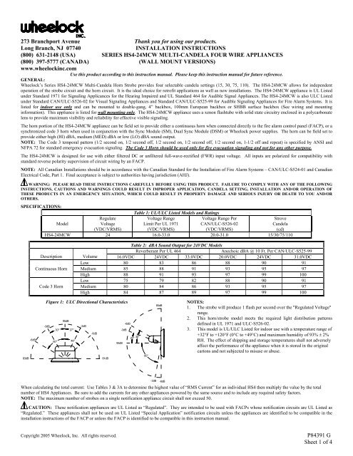
273 Branchport Avenue Thank you for using our products.Long Branch, NJ 07740INSTALLATION INSTRUCTIONS(800) 631-2148 (USA) SERIES HS4-24MCW MULTI-CANDELA FOUR WIRE APPLIANCES(800) 397-5777 (CANADA) (WALL MOUNT VERSIONS)www.wheelockinc.comUse this product according to this instruction manual. Please keep this instruction manual for future reference.GENERAL:Wheelock’s Series HS4-24MCW Multi-Candela Horn Strobe provides four selectable candela settings (15, 30, 75, 110). The HS4-24MCW allows for independentoperation of the strobe circuit and the horn circuit. It is the ideal choice for retrofit applications as well as new installations. The HS4-24MCW appliance is UL Listedunder Standard 1971 for Signaling Applicances for the Hearing Impaired and UL Standard 464 for Audible Signal Appliances. The HS4-24MCW is also ULC Listedunder Standard CAN/ULC-S526-02 for Visual Signaling Appliances and Standard CAN/ULC-S525-99 for Audible Signaling Appliances for Fire Alarm <strong>Systems</strong>. It islisted for indoor use only and can be mounted to double-gang, 4” backbox, 100mm European backbox or SHBB surface backbox (See wiring and mountinginformation). This appliance is listed for wall mounting only. The HS4-24MCW appliance uses a xenon flashtube with solid state circuitry enclosed in a polycarbonatelens to provide maximum visibility and reliability for effective visible signaling.The horn portion of the HS4-24MCW appliance can be field set to provide either a continuous horn when connected directly to the fire alarm control panel (FACP), or asynchronized code 3 horn when used in conjunction with the Sync Module (SM), Dual Sync Module (DSM) or Wheelock power supplies. The horn can be field set toprovide either high (HI) dBA, medium (MED) dBA or low (LO) dBA sound output.NOTE: The Code 3 temporal pattern (1/2 second on, 1/2 second off, 1/2 second on, 1/2 second off, 1/2 second on, 1-1/2 off and repeat) is specified by ANSI andNFPA 72 for standard emergency evacuation signaling. The Code 3 Horn should be used only for fire evacuation signaling and not for any other purpose.The HS4-24MCW is designed for use with either filtered DC or unfiltered full-wave-rectified (FWR) input voltage. All inputs are polarized for compatibility withstandard reverse polarity supervision of circuit wiring by an FACP.NOTE: All Canadian <strong>Installation</strong>s should be in accordance with the Canadian Standard for the <strong>Installation</strong> of Fire Alarm <strong>Systems</strong> – CAN/ULC-S524-01 and CanadianElectrical Code, Part 1. Final acceptance is subject to authorities having jurisdiction (AHJ).WARNING: PLEASE READ THESE INSTRUCTIONS CAREFULLY BEFORE USING THIS PRODUCT. FAILURE TO COMPLY WITH ANY OF THE FOLLOWINGINSTRUCTIONS, CAUTIONS AND WARNINGS COULD RESULT IN IMPROPER APPLICATION, CANDELA SETTING, INSTALLATION AND/OR OPERATION OFTHESE PRODUCTS IN AN EMERGENCY SITUATION, WHICH COULD RESULT IN PROPERTY DAMAGE AND SERIOUS INJURY OR DEATH TO YOU AND/OROTHERS.SPECIFICATIONS:Table 1: UL/ULC Listed Models and RatingsModelRegulateVoltage(VDC/VRMS)Voltage RangeLimit Per UL 1971(VDC/VRMS)Voltage Range PerCAN/ULC-S526-02(VDC/VRMS)StroveCandela(cd)HS4-24MCW 24 16.0-33.0 20.0-31.0 15/30/75/110Table 2: dBA Sound Output for 24VDC ModelsReverberant Per UL 464Anechoic dBA @ 10 Ft. Per CAN/ULC-S525-99Description Volume 16.0VDC 24VDC 33.0VDC 20.0VDC 24VDC 31.0VDCLow 80 83 86 88 90 91Continuous Horn Medium 85 88 91 93 95 97High 88 91 93 97 99 100Low 75 79 82 88 90 91Code 3 Horn Medium 80 84 86 93 95 97High 84 87 89 97 99 100-6dBFigure 1: ULC Directional Characteristics95dB-6dB-3dB-3dB30° 27°-3dB-6dB60° 48°95dB85dBNOTES:1. The strobe will produce 1 flash per second over the "Regulated Voltage"range.2. This horn/strobe model meets the required light distribution patternsdefined in UL 1971 and ULC-S526-02.3. This model is UL/ULC Listed for indoor use with a temperature range of+32°F to +120°F (0°C to +49°C) and maximum humidity of 93% ± 2%RH. The effect of shipping and storage temperatures shall not adverselyaffect the performance of the appliance when it is stored in the originalcartons and not subjected to misuse or abuse.20° 30° 80°83dB81dB-3dB-6dBWhen calculating the total current: Use Tables 3 & 3A to determine the highest value of “RMS Current” for an individual HS4 then multiply the value by the totalnumber of HS4 Appliances. Be sure to add the currents for any other appliances powered by the same source and to include any required safety factors.NOTE: The maximum number of strobes on a single notification appliance circuit shall not exceed 50.CAUTION: These notification appliances are UL Listed as “Regulated”. They are intended to be used with FACPs whose notification circuits are UL Listed as“Regulated.” These appliances shall not be used on UL Listed “Special Application” notification circuits unless the appliances are identified to be compatible in theinstallation instructions of the FACP or unless the FACP is identified to be compatible in this instruction manual.Copyright 2005 Wheelock, Inc. All rights reserved.P84391 GSheet 1 of 4
WARNING: CANDELA SETTING WILL DETERMINE THE CURRENT DRAW OF THE PRODUCT.Table 3: Current Ratings (Horn Only)Maximum RMS Current AmpsVoltage Lo Med HiDC 16-33VDC 0.027 0.068 0.110FWR 16-33VRMS 0.041 0.050 0.094Table 3A: Current Ratings (Strobe Only)Maximum RMS Current AmpsVoltage 15cd 30cd 75cd 110cdDC 16-33VDC 0.060 0.092 0.165 0.220FWR 16-33VRMS 0.102 0.155 0.253 0.347WARNING: THESE APPLIANCES WERE TESTED TO THE REGULATED VOLTAGE LIMITS OF 16.0-33.0 VOLTS FOR 24V MODELS USING FILTERED DC ORUNFILTERED FULL-WAVE-RECTIFIED VOLTAGE. DO NOT APPLY VOLTAGE OUTSIDE OF THIS RANGE.WARNING: CHECK THE MINIMUM AND MAXIMUM OUTPUT OF THE POWER SUPPLY AND STANDBY BATTERY AND SUBTRACT THE VOLTAGE DROPFROM THE CIRCUIT WIRING RESISTANCE TO DETERMINE THE APPPLIED VOLTAGE TO THE STROBES. THE MAXIMUM WIRE IMPEDANCE BETWEENSTROBES SHALL NOT EXCEED 35 OHMS.WARNING: MAKE SURE THAT THE TOTAL RMS CURRENT REQUIRED BY ALL APPLIANCES THAT ARE CONNECTED TO THE SYSTEM’S PRIMARY ANDSECONDARY POWER SOURCES, APPLIANCE CIRCUITS, SM, DSM SYNC MODULES AND WHEELOCK POWER SUPPLIES DOES NOT EXCEED THE POWERSOURCES’ RATED CAPACITY OR THE CURRENT RATINGS OF ANY FUSES ON THE CIRCUITS TO WHICH THESE APPLIANCES ARE WIRED. OVERLOADINGPOWER SOURCES OR EXCEEDING FUSE RATINGS COULD RESULT IN LOSS OF POWER AND FAILURE TO ALERT OCCUPANTS DURING AN EMERGENCY,WHICH COULD RESULT IN PROPERTY DAMAGE AND SERIOUS INJURY OR DEATH TO YOU AND/OR OTHERS.CAUTION: The strobe is not designed to be used on coded systems in which the applied voltage is cycled on and off.NOTE: The horn circuit is compatible with coded systems only if the unit is wired for independent horn and strobe operation per figure 4.SOUND OUTPUT (SPL) AND CANDELA SETTINGS:Figure 2: Showing Location of Candela Selector and Jumper PlugsTOPCANDELA SELECTORP83511 ( )AHC1R5157530110BRJ3+ STR -J2J1 CH OM DL ETB 1 3+ AUD -J2J1HMLCODE3CANDELAPOINTERFactory setting is on 15 candela, Medium dB and Code 3.WARNING: THE CANDELA SELECT SWITCH MUST BE FIELD SET TO THE REQUIRED CANDELA INTENSITY BEFORE INSTALLATION. WHEN CHANGINGTHE SETTING OF THE CANDELA SELECT SWITCH, MAKE CERTAIN THAT IT “CLICKS” IN PLACE. AFTER CHANGING THE CANDELA SETTING, THEAPPLIANCE MUST BE RETESTED TO VERIFY PROPER OPERATION. IMPROPER SETTING OF THE CANDELA SELECT SWITCH MAY RESULT IN OPERATIONAT THE WRONG CANDELA, WHICH COULD RESULT IN A CURRENT DRAW EXCEEDING THE POWER SUPPLY’S CAPACITY.CAUTION: If these appliances are operated within 15 inches of a person's ear, they can produce a sound pressure level that exceeds the maximum 120dBApermitted by ADA and OSHA rules. Exposure to such sound levels can result in damage to a person's hearing.WARNING: THE HS4 APPLIANCES MUST BE FIELD SET TO THE DESIRED TONE AND dBA SOUND OUTPUT LEVEL BEFORE THEY ARE INSTALLED. THISIS DONE BY PROPERLY INSERTING JUMPER PLUGS IN ACCORDANCE WITH THESE INSTRUCTIONS. INCORRECT SETTINGS WILL RESULT IN IMPROPERPERFORMANCE, WHICH COULD RESULT IN PROPERTY DAMAGE AND SERIOUS INJURY OR DEATH TO YOU AND/OR OTHERS.HMLHIGHHORNSETTINGFigure 3: Jumper Plug Settings for High, Medium, Low dB,Code 3 Horn and Continuous Horn Setting.J2 J2 J2HMLMEDIUMHORNSETTINGHMLLOWHORNSETTINGJ1J1CCOODDEE3 3CODE 3 CONTINUOUSHORN * HORNSETTING SETTING• Use needle nose pliers to pull and properly insert the jumper plug.• No jumper plug is needed for continuous horn setting. However, it isrecommended that the jumper plug be retained in the unit for futureuse (if needed) as shown in Figure 3.• The HS4 must be set for Code 3 horn when used with the syncmodule. Refer to instruction sheets for SM (P83123), DSM(P83177) or Wheelock power supplies for additional information. Ifthe HS4 audible is connected to a coded system, the continuous hornsetting must be usedP84391 GSheet 2 of 4
WIRING AND MOUNTING INFORMATION:Figure 4: Audible signal and strobe operate independently.Figure 4A: Audible and strobe operate in unison. Shunt wires are supplied.FROM FIRE ALARMCONTROL PANEL (FACP),PRECEDING APPLIANCE +-OR SYNC MODULETO NEXT APPLIANCE +OR END OF LINE -RESISTOR (EOLR).TB1+ STR - + AUD -- FROM FACP OR+ PRECEDING APPLIANCE+ -TO NEXT APPLIANCEOR EOLR.FROM FACP,PRECEDING APPLIANCE +-OR SYNC MODULERED SHUNT WIRETB1+ STR - + AUD -BLACK SHUNT WIRE- TO NEXT APPLIANCE+ OR EOLRFigure 5:• HS4-24MCW Appliances have in-out wiring terminals that accepts two #12 to #18 American Wire Gauge (AWG) wires at each screwterminal. Strip leads 3/8” inches for connection to screw terminals.• Break all in-out wire runs on supervised circuit supervision as shown in Figure 5. The polarity shown in the wiring diagrams is for theoperation of the appliances. The polarity is reversed by the FACP during supervision.CAUTION: The following figures (A-D) show the maximum number of field wires (conductors) that can enter the backbox used with each mounting option. Ifthese limits are exceeded, there may be insufficient space in the backbox to accommodate the field wires and stresses from the wires could damage the product. Checkthat the installed product will have sufficient clearance and wiring room prior to installing backboxes and conduit, especially if sheathed multiconductor cable or 3/4"conduit fittings are used.Figure AFLUSH (4" BOX)4" SQ. X 2-1/8"DEEP BACKBOXFigure BFLUSH (2-GANG BOX)2-GANG x 3-1/2"DEEP BACKBOXAlthough the limits shown for each mounting option comply withthe National Electrical Code (NEC), Wheelock recommends use ofthe largest backbox option shown and the use of approved strandedfield wires, whenever possible, to provide additional wiring roomfor easy installation and minimum stress on the product fromwiring.MOUNTING PROCEDURES:#8-32 SCREWSSCREW COVERSMAXIMUM NUMBER OF CONDUCTORSAWG #18 AWG #16 AWG #14 AWG #128 8 8 4Figure CSURFACE MOUNTINGBACKBOX(IOB)#8-18 SCREWSWOOD SCREWSSCREW COVERSMAXIMUM NUMBER OF CONDUCTORSAWG #18 AWG #16 AWG #14 AWG #128 8 8 8#6-32 SCREWSSCREW COVERSMAXIMUM NUMBER OF CONDUCTORSAWG #18 AWG #16 AWG #14 AWG #128 8 8 8Figure DCONCEALED CONDUIT MOUNTINGEXISTINGBOX IN WALLBACKBOX(IOB)#8-18 SCREWSSCREW COVERSMAXIMUM NUMBER OF CONDUCTORSAWG #18 AWG #16 AWG #14 AWG #128 8 8 81. This HS4 model can be flush mounted to a 100mm backbox(Figure A) or double-gang backbox (Figure B). It can also besurface mounted to a indoor/outdoor backbox (Figures C & D).Mounting hardware for each mounting option is supplied.2. Conduit entrances to the backbox should be selected to providesufficient wiring clearance for the installed product. Do notpass additional wires (used for other than the signalingappliance) through the backbox. Such additional wires couldresult in insufficient wiring space for the signaling appliance.3. When terminating field wires, do not use more lead length thanrequired. Excess lead length could result in insufficient wiringspace for the appliance.4. Use care and proper techniques to position the field wires inthe backbox so that they use minimum space and produceminimum stress on the product. This is especially importantfor stiff, heavy gauge wires and wires with thick insulation orsheathing.5. Connect field wires to the HS4-24MCW terminal block(polarity must be observed). Bend the field wires up 90° at theconnection to the terminal block.6. Carefully push the field wires into the backbox by hand. Pressthe HS4-24MCW to the backbox, verifying that it is seated andaligned correctly.7. Fasten the HS4-24MCW to the backbox using the suppliedscrews.WARNING: THE HS4-24MCW APPLIANCE IS A “FIRE ALARM DEVICE – DO NOT PAINT.”WARNING: WHEN INSTALLING STROBES IN AN OPEN OFFICE OR OTHER AREAS CONTAINING PARTITIONS OR OTHER VIEWINGOBSTRUCTIONS, SPECIAL ATTENTION SHOULD BE GIVEN TO THE LOCATION OF THE STROBES SO THAT THEIR OPERATING EFFECTCAN BE SEEN BY ALL INTENDED VIEWERS, WITH THE INTENSITY, NUMBER, AND TYPE OF STROBES BEING SUFFICIENT TO MAKE SURETHAT THE INTENDED VIEWER IS ALERTED BY PROPER ILLUMINATION, REGARDLESS OF THE VIEWER'S ORIENTATION. FAILURE TODO SO COULD RESULT IN PROPERTY DAMAGE AND SERIOUS INJURY OR DEATH TO YOU AND/OR OTHERS.The HS4-24MCW’s 110cd setting is Listed for use in sleeping or non-sleeping areas when installed in accordance with appropriate NFPA Standards and the AHJ.WARNING: IF 110 CANDELA STROBES ARE INSTALLED IN SLEEPING AREAS, THEY SHOULD BE WALL MOUNTED AT LEAST 24"BELOW THE CEILING AS FOLLOWS: (1) THE ON-AXIS (CENTER OF LENS) LIGHT OUTPUT SHOULD BE DIRECTED AT THE EYELIDS OFTHE SLEEPING PERSON, E.G. PILLOW END OF BED, BED HEAD; (2) NO PART OF THE BED SHALL BE MORE THAN SIXTEEN FEET FROMP84391 GSheet 3 of 4
THE STROBE NOTIFICATION APPLIANCE. INSTALLERS MUST ADVISE OWNERS AND OPERATORS OF BUILDINGS WITH SLEEPINGOCCUPANTS, E.G. HOTELS AND MOTELS, TO WARN GUESTS, RESIDENTS AND EMPLOYEES TO NOT MOVE THE BED LOCATION TO APOSITION VIOLATING POINTS (1) AND (2) ABOVE OR SERIOUS INJURY AND/OR LOSS OF LIFE MAY OCCUR DURING A FIRE EMERGENCY.WARNING: A SMALL POSSIBILITY EXISTS THAT THE USE OF MULTIPLE STROBES WITHIN A PERSON'S FIELD OF VIEW, UNDER CERTAINCIRCUMSTANCES, MIGHT INDUCE A PHOTO-SENSITIVE RESPONSE IN PERSONS WITH EPILEPSY. STROBE REFLECTIONS IN A GLASS OR MIRROREDSURFACE MIGHT ALSO INDUCE SUCH A RESPONSE. TO MINIMIZE THIS POSSIBLE HAZARD, WHEELOCK STRONGLY RECOMMENDS THAT THE STROBESINSTALLED SHOULD NOT PRESENT A COMPOSITE FLASH RATE IN THE FIELD OF VIEW WHICH EXCEEDS FIVE Hz AT THE OPERATING VOLTAGE OF THESTROBES. WHEELOCK ALSO STRONGLY RECOMMENDS THAT THE INTENSITY AND COMPOSITE FLASH RATE OF INSTALLED STROBES COMPLY WITHLEVELS ESTABLISHED BY APPLICABLE LAWS, STANDARDS, REGULATIONS, CODES AND GUIDELINES.NOTE: NFPA 72/ANSI 117.1 conform to ADAAG Equivalent Facilitation <strong>Guide</strong>lines in using fewer, higher intensity strobes within the same protected area.CAUTION: Check the installation instructions of the manufacturers of other equipment used in the system for any guidelines or restrictions on wiring and/orlocating Notification Appliance Circuits (NAC) and notification appliances. Some system communication circuits and/or audio circuits, for example, may requirespecial precautions to assure electrical noise immunity (e.g. audio crosstalk).NOTE: This equipment has been tested and found to comply with the limits for a Class B digital appliance, pursuant to Part 15 of the FCC Rules. These limits aredesigned to provide reasonable protection against harmful interference in residential installation. This equipment generates, uses and can radiate radio frequency energyand, if not installed and used in accordance with the instructions, may cause harmful interference to radio communications. However, there is no guarantee thatinterference will not occur in a particular installation. If this equipment does cause harmful interference to radio or television reception, which can be determined byturning the equipment off and on, the user is encouraged to try to correct the interference by one or more of the following measures: 1) Reorient or relocate thereceiving antenna, 2) Increase the separation between the equipment and receiver, 3) Connect the equipment into an outlet on a circuit different from that to which thereceiver is connected, and 4) Consult the dealer or an experienced radio/TV technician for help.The Series HS4 products and these instructions are copyrighted by Wheelock and the Series HS4 products contain proprietary, confidential and trade secrets ofWheelock. No part of the Series HS4 products and these instructions may be photocopied, printed or reproduced in any form or modified, adapted, changed orenhanced, or converted to another programming language, or used to create updated, related or derivative works, without the prior written consent of Wheelock. Nopart of the Series HS4 products shall be decomposed, disassembled or reverse engineered.ANY MATERIAL EXTRAPOLATED FROM THIS DOCUMENT OR FROM WHEELOCK MANUALS OR OTHER DOCUMENTS DESCRIBING THE PRODUCT FOR USEIN PROMOTIONAL OR ADVERTISING CLAIMS, OR FOR ANY OTHER USE, INCLUDING DESCRIPTION OF THE PRODUCT'S APPLICATION, OPERATION,INSTALLATION AND TESTING IS USED AT THE SOLE RISK OF THE USER AND WHEELOCK WILL NOT HAVE ANY LIABILITY FOR SUCH USE.IMPORTANT: READ SEPARATE "GENERAL INFORMATION" SHEET FOR INFORMATION ON THE PLACEMENT, LIMITATIONS, INSTALLATION, FINALCHECKOUT, AND PERIODIC TESTING OF NOTIFICATION APPLIANCES.Limited WarrantyWheelock products must be used within their published specifications and must be PROPERLY specified, applied, installed, operated, maintained and operationallytested in accordance with these instructions at the time of installation and at least twice a year or more often and in accordance with local, state and federal codes,regulations and laws. Specification, application, installation, operation, maintenance and testing must be performed by qualified personnel for proper operation inaccordance with all of the latest National Fire Protection Association (NFPA), Underwriters' Laboratories (UL), Underwriters’ Laboratories of Canada (ULC), NationalElectrical Code (NEC), Occupational Safety and Health Administration (OSHA), local, state, county, province, district, federal and other applicable building and firestandards, guidelines, regulations, laws and codes including, but not limited to, all appendices and amendments and the requirements of the local authority havingjurisdiction (AHJ). Wheelock products when properly specified, applied, installed, operated, maintained and operationally tested as provided above are warrantedagainst mechanical and electrical defects for a period of three years from date of manufacture (as determined by date code). Correction of defects by repair orreplacement shall be at Wheelock sole discretion and shall constitute fulfillment of all obligations under this warranty. THE FOREGOING LIMITED WARRANTYSHALL IMMEDIATELY TERMINATE IN THE EVENT ANY PART NOT FURNISHED BY WHEELOCK IS INSTALLED IN THE PRODUCT. THEFOREGOING LIMITED WARRANTY SPECIFICALLY EXCLUDES ANY SOFTWARE REQUIRED FOR THE OPERATION OF OR INCLUDED IN APRODUCT. WHEELOCK MAKES NO REPRESENTATION OR WARRANTY OF ANY OTHER KIND, EXPRESS, IMPLIED OR STATUTORY WHETHER ASTO MERCHANTABILITY, FITNESS FOR A PARTICULAR PURPOSE OR ANY OTHER MATTER.USERS ARE SOLELY RESPONSIBLE FOR DETERMINING WHETHER A PRODUCT IS SUITABLE FOR THE USER'S PURPOSES, OR WHETHER IT WILLACHIEVE THE USER'S INTENDED RESULTS. THERE IS NO WARRANTY AGAINST DAMAGE RESULTING FROM MISAPPLICATION, IMPROPERSPECIFICATION, ABUSE, ACCIDENT OR OTHER OPERATING CONDITIONS BEYOND WHEELOCK'S CONTROL.SOME WHEELOCK PRODUCTS CONTAIN SOFTWARE. WITH RESPECT TO THOSE PRODUCTS, WHEELOCK DOES NOT WARRANTY THAT THEOPERATION OF THE SOFTWARE WILL BE UNINTERRUPTED OR ERROR-FREE OR THAT THE SOFTWARE WILL MEET ANY OTHER STANDARD OFPERFORMANCE, OR THAT THE FUNCTIONS OR PERFORMANCE OF THE SOFTWARE WILL MEET THE USER'S REQUIREMENTS. WHEELOCKSHALL NOT BE LIABLE FOR ANY DELAYS, BREAKDOWNS, INTERRUPTIONS, LOSS, DESTRUCTION, ALTERATION, OR OTHER PROBLEMS IN THEUSE OF A PRODUCT ARISING OUT OF OR CAUSED BY THE SOFTWARE.THE LIABILITY OF WHEELOCK ARISING OUT OF THE SUPPLYING OF A PRODUCT, OR ITS USE, WHETHER ON WARRANTIES, NEGLIGENCE, OROTHERWISE, SHALL NOT IN ANY CASE EXCEED THE COST OF CORRECTING DEFECTS AS STATED IN THE LIMITED WARRANTY AND UPONEXPIRATION OF THE WARRANTY PERIOD ALL SUCH LIABILITY SHALL TERMINATE. WHEELOCK IS NOT LIABLE FOR LABOR COSTS INCURREDIN REMOVAL, REINSTALLATION OR REPAIR OF THE PRODUCT BY ANYONE OTHER THAN WHEELOCK OR FOR DAMAGE OF ANY TYPEWHATSOEVER, INCLUDING BUT NOT LIMITED TO, LOSS OF PROFIT OR INCIDENTAL OR CONSEQUENTIAL DAMAGES. THE FOREGOING SHALLCONSTITUTE THE SOLE REMEDY OF THE PURCHASER AND THE EXCLUSIVE LIABILITY OF WHEELOCK.IN NO CASE WILL WHEELOCK'S LIABILITY EXCEED THE PURCHASE PRICE PAID FOR A PRODUCT.Limitation of LiabilityWHEELOCK'S LIABILITY ON ANY CLAIM OF ANY KIND, INCLUDING NEGLIGENCE AND BREACH OF WARRANTY, FOR ANY LOSS OR DAMAGERESULTING FROM, ARISING OUT OF, OR CONNECTED WITH THIS CONTRACT, OR FROM THE MANUFACTURE, SALE, DELIVERY, RESALE,REPAIR OR USE OF ANY PRODUCT COVERED BY THIS ORDER SHALL BE LIMITED TO THE PRICE APPLICABLE TO THE PRODUCT OR PARTTHEREOF WHICH GIVES RISE TO THE CLAIM. WHEELOCK'S LIABILITY ON ANY CLAIM OF ANY KIND SHALL CEASE IMMEDIATELY UPON THEINSTALLATION IN THE PRODUCT OF ANY PART NOT FURNISHED BY WHEELOCK. IN NO EVENT SHALL WHEELOCK BE LIABLE FOR ANYCLAIM OF ANY KIND UNLESS IT IS PROVEN THAT OUR PRODUCT WAS A DIRECT CAUSE OF SUCH CLAIM. FURTHER, IN NO EVENT, INCLUDINGIN THE CASE OF A CLAIM OF NEGLIGENCE, SHALL WHEELOCK BE LIABLE FOR INCIDENTAL OR CONSEQUENTIAL DAMAGES. SOME STATESDO NOT ALLOW THE EXCLUSION OR LIMITATION OF INCIDENTAL OR CONSEQUENTIAL DAMAGES, SO THE PRECEDING LIMITATION MAY NOTAPPLY TO ALL PURCHASERS.11/05P84391 GSheet 4 of 4