Figure 8A-12D: Inlet Protection (Type 4)
Figure 8A-12D: Inlet Protection (Type 4)
Figure 8A-12D: Inlet Protection (Type 4)

You also want an ePaper? Increase the reach of your titles
YUMPU automatically turns print PDFs into web optimized ePapers that Google loves.
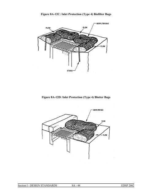
<strong>Figure</strong> <strong>8A</strong>-12C: <strong>Inlet</strong> <strong>Protection</strong> (<strong>Type</strong> 4) Biofilter Bags<strong>Figure</strong> <strong>8A</strong>-<strong>12D</strong>: <strong>Inlet</strong> <strong>Protection</strong> (<strong>Type</strong> 4) Blotter BagsSection I - DESIGN STANDARDS <strong>8A</strong> - 44 EDSP 2002
<strong>Figure</strong> <strong>8A</strong>-12E: <strong>Inlet</strong> <strong>Protection</strong> (<strong>Type</strong> 5) Masonry AggregateA. Applications1. At inlets ready for use before completion of final stabilization and which receive runofffrom drainage areas less than one acre in size.2. At storm drain inlets downslope and within 500 feet of a disturbed area or constructionentrance.3. As a secondary measure downstream from erosion prevention and sediment trappingmeasures.B. Advantages1. Prevents sediment from entering the storm drain system.2. Reduces amount of sediment leaving the site.C. Disadvantages1. Useful only for LOW flows having LOW sediment loading,2. May result in ponding of water above the catch basin.3. Sediment removal may be difficult under high-flow conditions.4. May result in a traffic hazard.5. Short-circuiting of flow may occur if not properly installed.6. Improper installation, maintenance, or removal may introduce sediment and aggregateinto the storm drain system.D. Design Criteria1. Place inlet protection in areas where water can pond and where ponding will not haveadverse impacts.2. <strong>Inlet</strong> protection must allow for overflow in a severe storm event.3. <strong>Inlet</strong> protection types include:a. Sediment fence.b. Geotextile with aggregate filter.c. Catch basin insert.d. Biofilter bags.e. Masonry aggregate.f. Sod.Section I - DESIGN STANDARDS <strong>8A</strong> - 45 EDSP 2002
Table <strong>8A</strong>-8: <strong>Inlet</strong> <strong>Protection</strong> Selection Based on Site ConditionsSite Conditions<strong>Inlet</strong> <strong>Protection</strong> <strong>Type</strong>1 2 3 4 5 6Area Drain, Soil Y Y Y Y Y YArea Drain, Pavement N Y Y Y N NDitch <strong>Inlet</strong>, Soil Y N Y Y N YDitch <strong>Inlet</strong>, Pavement N N Y Y N NGrate <strong>Inlet</strong> Along Curb, Soil N Y Y Y Y NGrate <strong>Inlet</strong> Along Curb, N Y Y Y N NCurb Opening <strong>Inlet</strong>, Soil N N N Y Y YCurb Opening <strong>Inlet</strong>, Pavement N N N Y N NE. Maintenance1. Inspect and clean inlet protection during and after each significant storm and removesediment from behind structure after every storm.2. If the aggregate becomes clogged with sediment, it must be carefully removed from theinlet and either cleaned or replaced.3. Assess the impacts of allowing water to pond at the inlet and provide an overflow weiror some other type of relief as needed. Consider the effect of placing obstructions atinlets on grade may have on their efficiency.4. When possible, include a sediment sump 12 to 24 inches deep with 4H:1V side slopes.5. Do not use water to remove sediment.6. Remove sediment accumulated on or around the protection as needed to maintainintended functions.7. Repair or replace materials as needed to ensure proper functioning.F. Common FailuresThe most common problems with this BMP include torn geotextile material, improperlysealed gaps in the inlet structure, and aggregate that becomes filled with sediment.Section I - DESIGN STANDARDS <strong>8A</strong> - 46 EDSP 2002
<strong>8A</strong>.04.4Sediment Trap<strong>Figure</strong> <strong>8A</strong>-13: Sediment TrapA sediment trap consists of a small, temporary ponding area with a rock weir or perforated riser pipeat the outlet formed by excavation or by constructing a weir. The sediment trap serves drainageareas five acres and smaller and has a design life of approximately six months.A. Applications1. Drainage areas which are 5 acres and smaller.2. Sites in proximity to rivers/streams, wetlands, or phosphorus-sensitive water bodies.3. Sites where major clearing and grading is likely to occur during the wet season.4. Sites with downstream erosion or sedimentation problems.5. Downslope of disturbed areas.B. Combining with Permanent Drainage Facilities1. If a project includes a permanent storm water retention/detention pond, the rough gradedor final-graded facility could function as a trap during construction. Design features ofthe permanent structure, such as surface area, retention time, and outlet control, shouldmeet the design requirements of the temporary facility. Completion of the permanentfacility should occur only when all upstream control structures are in place andstabilization of contributing drainage areas is complete.2. If a project includes an infiltration facility, the roughly excavated facility could be usedas a trap or basin the facility provides the surface area and retention time required by thetrap or basin. Excavate the sides and bottom of the facility to a minimum of two feetabove final grade with a backhoe working at "arms length" to minimize disturbance andcompaction of the infiltration surface.Section I - DESIGN STANDARDS <strong>8A</strong> - 47 EDSP 2002
3. In addition, any required pre-treatment facilities should be fully constructed prior to anyrelease of sediment-laden water to the facility. Pre-treatment and shallow excavationsare intended to prevent the clogging of soil with fines.C. Advantages1. Protects downstream riparian properties from sediment deposits.2. Prevents reduced downstream capacity due to sediment deposition in a stream channel.3. Prevents clogging of downstream facilities.4. Removes particles up to medium silt size (0.02 mm).5. Surface water conveyances can be connected to the facility as site development proceeds.The engineer may want to route surface water collected from disturbed areas of the sitethrough a sediment trap prior to release from the site.D. Disadvantages1. May become an attractive nuisance. Care must be taken to adhere to all safety practices.2. Maintenance and sediment removal are essential for adequate performance.3. Serves limited areas.4. Does not reduce turbidity resulting from fine silts and clays in runoff. Traps are moreeffective when used in conjunction with other measures such as seeding and mulching.E. Design Criteria1. Construct prior to any upslope clearing and grading.2. Locate in a low area where the trap will intercept all or most of the runoff from thedisturbed area before it enters a waterway, considering safety in case structure fails.3. Locate the trap so that it is readily accessible for maintenance.4. Provide for diversion dikes and ditches, as needed, to collect and divert water toward thetrap.5. Design the trap with a level bottom, 3H:1V or flatter side slopes and a L:W ratio of 3.Because sediment traps are temporary, the sizing is less important to proper functioningthan is constant maintenance.6. Construct the trap as the first step in the clearing and grading of the site.7. Form the trap by excavation or by construction of compacted embankment. If the trapis formed by embankment, the engineer should note that dam safety regulation mayapply to heights exceeding five feet. The embankment should be stabilized using a covermethod such as seeding, mulching, or erosion control matting,8. Do not drain traps directly into a stream, lake, or other waterway. Water temperature inthe trap may be too high for direct release. Always moderate the water temperaturebefore it drains into a lake, stream, wetland, or waterway. Whenever possible, releasethe trap discharge on site onto a relatively level, densely grassed area at least 75 feetfrom a waterway or wetland.9. Evaluate the release areas on a site-by-site basis in order to determine appropriatelocations for and methods of releasing runoff.F. Sediment Trap SizingSediment traps must be sized to handle the area contributing sediment-laden runoff. Thefollowing design criteria is based on a variation of the Rational Formula, allowing arelatively simple set of calculations to be used to size the traps while accounting for rainfallpatterns that occur. Facilities designed to collect contributing areas up to five acres can usethese design criteria. Facilities designed to collect contributing areas larger than five acresmust use more thorough design criteria and would then be considered a Sediment Basin.Section I - DESIGN STANDARDS <strong>8A</strong> - 48 EDSP 2002
STEP 1:A. Calculate the Storage Volume (V), using a variation of the Rational Formula.B. Determine the volume of rainfall generated by the six-hour rainfall event with a onequarterinch per hour intensity over the contributing area to the trap.V(ft 3 ) = C x I (in/hr) x A (acre) x D (sec)Where:V = Storage Volume (ft 3 )C = Runoff Coefficient (from Table <strong>8A</strong>-9)I = 0.25 (in/hr) = Rainfall IntensityA = Contributing Area (Acres)D = 21600 seconds (6 hrs) = DurationSTEP 1-A:Determine area contributing sediment-laden runoff to the sediment trap.A = Contributing Area (acres)STEP 1-B:Determine the runoff coefficient(s) for the contributing area(s) using Table<strong>8A</strong>-9.Table <strong>8A</strong>-9: Runoff Coefficients for the Rational MethodFlat 10%2% - 10%AC or PCC Paving 0.90 0.90 0.90Gravel Pavement 0.50 0.55 0.60Roof Areas 0.90 0.90 0.90Light Residential (1-3 units/acre) 0.35 0.40 0.45Normal Residential (4-6 units/acre) 0.50 0.55 0.60Dense Residential (>7 units/acre) 0.70 0.75 0.80Light Industrial 0.50 0.70 0.80Heavy Industrial 0.60 0.80 0.90Commercial 0.80 0.85 0.90Vegetated Soil 0.25 0.30 0.35Bare Soil (Clay or Silt) 0.50 0.55 0.60Bare Soil (Sand/Gravel) 0.25 0.30 0.35Woodlands/Forest 0.10 0.15 0.20Section I - DESIGN STANDARDS <strong>8A</strong> - 49 EDSP 2002
STEP 1-C: Determine the volume of required storage.By using the formula described in STEP 1 and applying the constants, the formula canbe simplified from:V(ft 3 ) = C x 0.25 (in/hr) x A (acre) x 21600 (sec)to:V(ft 3 ) = 5400 x [3 (C 1 A 1 ) + (C 2 A 2 ) + . . . + (C x A x )]Divide the storage volume evenly between dry and wet storage. The wet storagenormally occupies the bottom two-thirds of the trap depth.STEP 2:Calculate the dimensions of the sediment trap by satisfying the volumerequirements. The trap dimensions must be assumed and then the volume ofthe trap based on the initial assumptions can be calculated using thefollowing:V = [LWD] = [ (L + W) ZD 2 ] + [4/3 Z 2 D 3 ]Where:V = Storage Volume (ft 3 )W = Width of Trap on Bottom (ft)L = Length of Trap on Bottom (ft)D = Depth of Trap (ft)Z = Side slope (Z:1; horizontal to vertical)The Volume of the proposed trap size must be equal to or exceed the volume of therequired storage capacity calculated in Step 1.STEP 3: Outlet Structure Design: The outlet structure for a temporary sediment trapshould be sized to handle expected flows. For most sediment traps a rockweir (spillway) will be sufficient. For larger flows or areas with heavysediment loading, a perforated riser pipe may need to be used as outlet to thetrap.G. Rock WeirThe crest of the weir should be one foot below the top of the embankment. The weir shouldbe constructed of two layers of different size rock. The top foot must be three to six inchesof riprap. The bottom layer should be of a smaller size.The weir length (X) can be estimated using the broad crested weir equation and assuminga one-inch flow depth over the weir (H). The amount of flow going over the weir can beestimated using the information developed for sizing the trap. Assume a weir coefficient(C w ) of 1.6.(Rational Formula)Q = C I ASection I - DESIGN STANDARDS <strong>8A</strong> - 50 EDSP 2002
(Broad Crested Weir Formula) X = QC W H 3/2Where:Q = Flow (ft 3 /sec)C = Runoff Coefficient (from Table <strong>8A</strong>-9)I = 0.25 (in/hr) = Rainfall IntensityA = Contributing Area (Acres)C w = 1.6 = weir coefficientH = 0.0833 ft = flow depth (assumed)X = Wier Length (ft)Therefore:X = C I A = CA 0.25 = 6.5 [3 (C 1 A 1 ) + (C 2 A 2 ) + . . . + (C x A x )]C W H 3/2 1.6 x (0.0833) 3/2H. Riser PipeAn alternate to the rock weir outlet is a riser pipe. A typical detail for the riser pipe shouldshow the following:1. Pipe slit perforations, which are 0.5 inches wide by six inches long or one-inch diameterholes spaced six inches vertically and horizontally from the outside edges above the wetstorage elevation.2. The riser pipe should be wrapped with 0.25 to 0.50 inch wire hardware cloth and coveredwith geotextile overlapped, folded and fastened at the seam. The geotextile shouldextend six inches above and below the highest and lowest slits and should be secured topand bottom with straps or connecting bands.3. Anchor the riser using a concrete or steel base. The concrete base should be 20 inchesdeep with the riser embedded ten inches. The steel base should be 0.25 inches thick,welded watertight to the riser and covered with 24 inches of stone or gravel.4, Table <strong>8A</strong>-10 gives riser pipe diameters for different size drainage areas.Maximum DrainageArea (acres)Table <strong>8A</strong>-10: Outlet Riser Pipe DiametersMinimum BarrelDiameter (in)Minimum RiserDiameter (in)1 12 152 15 183 18 214 21 245 21 275. A list of recommended size limits must be checked prior to completing the trap sizingcalculations. These limits are included in Table <strong>8A</strong>-11.Section I - DESIGN STANDARDS <strong>8A</strong> - 51 EDSP 2002