THE VIBRATORY PILE INSTALLATION TECHNIQUE - Viking
THE VIBRATORY PILE INSTALLATION TECHNIQUE - Viking
THE VIBRATORY PILE INSTALLATION TECHNIQUE - Viking

You also want an ePaper? Increase the reach of your titles
YUMPU automatically turns print PDFs into web optimized ePapers that Google loves.
to the three above mentioned engineering issues, which is further addressed in section ‘Choiceof vibratory driver related parameters’.2. Modern vibratory driving equipmentThere are two types of modern vibratory-equipment commercially available, and these are ‘freehanging’ and ‘leader mounted’ systems. Hydraulic vibratory driving equipment predominates themarket because they are both lighter in weight compared to electrical, and hydraulic allows bothfrequency as well as eccentricity adjustments. Advantages with free-hanging systems includelower costs and grater reach. In addition, they can also be more beneficial when bearingcapacity of the underlying soil is low. Built in limitations are lack of both controlling and guidingthe pile to desired position, as well as changing the static surcharge force during the installation.The built in advantages of the leader-mounted system enables the system to operate withgreater precision with respect to positioning, displacement amplitude, as well as driving andextracting forces. Drawbacks are usually costs together with weight, which can cause stabilityproblem at the construction site. However, the main parts of leader-mounted equipments areessentially the same as free hanging systems, and consist of the following parts, (see Fig. 1).- Power source; normally a basic hydraulic power pack containing necessary components toboth power and control the equipment.- Power transmission; high-pressure hydraulic hoses and electrical cables for signal andsensor control.- The vibro-unit; is the part of the equipment that generates the sinusoidal motion of the pileprofile, and finally.- The pile profile; intended to be installed.Both ‘free hanging’ and ‘leader mounted’ systems can be equipped with different type of vibrounits.However, vibro-units used for ‘free hanging’ are normally constructed with rotatingeccentric weights laid horizontally, and ‘leader mounted’ normally has their rotating eccentricweights stacked vertically, with main reason to make them less bulky and to be able to raise theunit along the leader without stability problems.2.1. Mechanical action of vibratory drivers/extractorsThe generated driving force F d governs the mechanical action of a vibratory driver, which in turnconsist of the two parts; a stationary part F o and a dynamic part F v , schematically illustrated byfigure 2. The in time stationary part F o (further explained below), and the dynamic part F vgoverned by the counter-rotating eccentric masses within the exciter block of the vibro-unit.The generated driving force F d = F o + F v , (imparted to the pile head), is governed by thefollowing ‘vibro-related parameters’.2.1.1. Surcharge forceF o is in the case of a "free-hanging" vibro represented by the sum of the dead weight of the biasmass W, minus the suspension force T of the carrier (crane), according to F o =W-T, (see Fig. 5).The surcharge force of a "leader mounted" vibro consist of the dead weight of the bias mass W,plus/minus the hydraulically applied pre-stress/tension force P=P o A cyl , which is controlled by thehydraulic pressure P o generated on the area A cyl of leader cylinder II, (see Fig. 1), according toF o =W±P.2.1.2. Eccentric momentM e is given in pound-inch [kg-m] and computed by the product of the eccentric weight W e [kg]and the radius of gyration r e [m] (i.e. distance between centre of the motor shafts and thegravity centre of the rotating eccentric weight).67
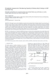
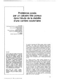
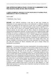
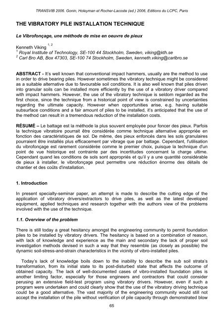
2.1.3. Driving frequencyf d is specified by the revolution per second of the eccentric weights [Hz], sometimes alsospecified as revolution per minute n [rpm]. Another common expression is revolution in radiansper second ω [rad/s]. The three different ways can be combined as follows: ω =2πf d =2πn/60.time [s]ω [rad/s]F oω = 2πf dF o^F v= ξM e( 2πf d) 2F da.) Driving force F dvs. timeT=1/f dDriving force: F d25% . M e50% . M e75% . M e100% . M eb.) Peak value of F dvs. M eand f dFigure 2. Driving force as a function of changed frequency and eccentric moment.2.1.4. System efficiencyξ which is applied to the dynamic part, (centrifugal force F v ), of the theoretical expression of thedriving force F d (see equation below). Since the actual driving force F d delivered to the pile headwill always be less than the theoretically rated.The theoretical peak amplitude of the driving force F d in [kN] can be assessed by the followingexpression.F d = F o + ξF v = F o + ξM e ω 2 = F o [kN] + ξ [-] M e [kg-m] (2πn) 2 [rpm] 22.2. Parts and type of vibro-unitsThe main parts of modern vibro-units consist of the following parts.Bias mass; a part of the vibrator that’s also called ‘suppressor housing’ which is the nonvibratingpart of the unit. It connects to the exciter block via elastomers pads that isolate thedynamic motion of the exciter block from being transmitted to either crane line or leader mast,which connects, to the bias mass. To the bias mass are also electrical cables, hydraulic hosesmast connected.Elastomer pads (or springs); connects and at the same time isolates the non-vibrating part fromthe vibrating part of the vibro-unit.Exciter block; contains the rotating eccentric weights, gearbox and hydraulic motor, whichcombined generates the sinusoidal motion and centrifugal force of the vibrator.Clamp; at the bottom of the vibro-unit, which forms the rigid connection between pile and vibrounit.Used to transfer the generated force and motion, (preferably ‘axially’), to the pile profile.The clamp must be adapted to the size of the vibro as well as to the shape of the pile.Five different types of vibratory drivers (free or leader mounted) can be distinguished, based onapplied driving frequency (f d [Hz]) and eccentric moment (M e [kg-m]), see Table I.Table I. Type of modern vibratory drivers/extractors.68
TypeFrequencyrange[rpm]Eccentricmoment M e[lb-in.]Max F vforce[tons]Displacementamplitude S p[in.]1.) Standard20,835 517 1.26< 1,800frequency2.) High520 – 3,980 45 - 303 0.51 – 0.87> 1,800frequency3.) Variable866 – 4,670 67 - 371 0.55 – 0.671,800 - 2,400eccentricity4.) Excavator90 – 1,125 8 - 56 0.24 – 0.791,800 - 3,000mounted5.) Directional♣ ♣ ♣force ♣ 1,800 - 2,400♣ Still not commercially available, but considered as the next generation of vibratory drivers.2.3. type of vibratory drivers/extractors2.31. Standard frequencyStandard frequency are still the vast majority of vibro-units in use today since they combine afrequency range that interacts properly with most soils, and generates sufficient displacementamplitude to penetrate denser sub-surface strata’s. These units are primarily used for heavypiles and large toe resistance such as concrete and large steel pipe piles. They are at the sametime the simplest, but also the most powerful, since they are able to generate both the highestdriving force and displacement amplitude due to being equipped with the largest eccentricweights.2.3.2. High frequencyThese units are the second generation of vibrators. They were primarily developed to meet thehigher demands of reduced transmission of harmful ground vibrations to neighboring structures,which can cause undesirable settlements. This was accomplished by using higher drivingfrequencies (>30 Hz). However, these units are not as powerful as standard units, they are alsoless successful in overcoming large toe resistance compare to standard units since they do notgenerate as high displacement amplitudes.2.3.3. Variable eccentricityAlso known as resonant-free vibrators, are the third generation, and they distinguishesthemselves through their ability to start up and stop without resonant vibrations. This isaccomplished by adjusting the eccentric moment on the fly, (read adjusting the displacementamplitude on the fly). These units are considered as the “state of the art equipment” in theapplication of the vibratory installation technique to drive piles. Their applications areadvantageous in densely populated areas or city centers and for the use on vibration-sensitivejobs: i.e. near old buildings and/or hospitals with sensitive equipment (computers)…2.3.4. Excavator mountedRefers to vibro-units that are typically quick and easy to connect to the excavator boom of abackhoe with a swivel connection after that the bucket is removed. The small excavatormounted vibro-units uses normally both the existing electric circuit and hydraulic system of thebackhoe. The excavator-mounted unit is used for small or remote jobs where a cost effectivemethod is needed to vibrate a few piles. They are also ideal for low height applications andwhere a long reach is required to vibrate sheets, beams or casings.69
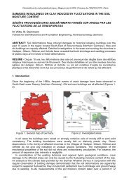
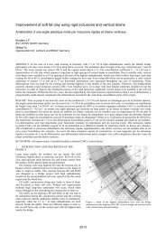
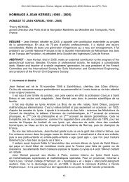
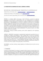
Figure 3. Directional vibrator; a.) ratio of new directional- and sinusoidal force,b.) principle of new vibrator (ABI 2004).2.3.5. Directional forceNoteworthy amongst the recent developments is the so-called “directional vibrator”. Figure 3ashows the principal difference between a standard unit and the new directional vibrator. Theusual sin wave is modified in order to generate more centrifugal force F v in the driving directionand less in the other, which is accomplished by new eccentric weights within the gearbox (fig3b). The soil surrounding the pile cannot follow the larger acceleration in the driving direction;the pile therefore rips away from the surrounding soil, illustrated by a circle in figure 3a. Due tothe decoupling of soil and pile during parts of each driving cycle, less energy is transferred intothe ground and therefore reduces the amount of transmitted ground vibrations to thesurrounding environment. The directional vibrator is also less noisy (due to new bearings), itcan sustain harder driving and is more efficient (needs ~30% less energy). However, the newdirectional force vibrator is at present not in production, however two prototypes havesuccessfully gone through both conducted laboratory as well as full-scale field tests.T=1/f dt 1t 2t 3t 4 t 5time [s]u 1u 2Penetrative motion: u(t) [in.]u 5u 4u 3sos opermanentsetdownward motion1uppwardmotionv pFigure 4. Penetrative motion of a vibratory driven pile (<strong>Viking</strong> 2002).2.4. Penetrative motion of vibratory driven pilesThe penetrative motion u(t) of a vibratory driven pile is best described by a downwardly-directedsinusoidal motion in time, in accordance with figure 4, and the following expression:u(t) = tv p + s o sin(ωt)70
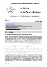
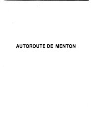
The magnitude of the penetration speed v p (read vibro-drivability) in the expression of thepenetrative motion u(t) corresponds, (in theory), to the dynamic equilibrium of the forces actingon the system. Which are generally evaluated by applying Newton’s second law(F o + ξF v - R t - R s - R c = am dyn ), as schematically graphed by figure 5. However, the applicationof Newton’s second law is only justified if the system behaves as a rigid body. Section ‘Theaxial rigidity assumption’ describes a rule of thumb, which can be applied in order to check if thevibro-pile-system tends to behave as a rigid body.The vibro-parameter S p =2s o named “displacement amplitude”, is normally listed in the specs ofvibro-manufacturers. However, the manufacturer provided specs normally refers to S p as thepeak-to-peak amplitude of a free hanging vibro-unit, without weight of pile and clamp. However,the theoretically generated displacement amplitude S p of a free vibrating pile is assessed by thefollowing expression.2M e 2M e [lb-in.]S p = -------- = ---------------------------------------m dyn (m v [lb] + m c [lb] + m p [lb])The theoretical value of S p is governed by; the dynamic mass m dyn (weight of vibrator m v , clampm cl , and pile m p ) and the eccentric moment M e . However, it’s an expression that omits effects ofsoil resistance as well as developed energy losses, it should therefore be noted by the readerthat the in field observed value of S p will always be less than the theoretically estimated value.2.5. Choice of vibratory driver related parametersChoice of vibro-parameters amongst practitioners is generally based on previous experienceand field verifications. Rodger et al., 1980 have summarized their experience into a tablerecommending driving frequency and displacement amplitude for different piles and soil types.Those recommendations are reproduced herein as Table II.Table II. Recommended choice of vibratory driver parameters in relationto type of soil and pile, (Rodger et al., 1980).Cohesive soils Dense cohesionless soils Loose cohesionless soilsAll situationsLow toe High toe Heavy piles Light pilesresistance resistanceHigh acceleration.Low displacementamplitude.High accelerationLow frequency, and largedisplacement amplitude.High acceleration.Predominant shaftresistance.Predominantshaft resistance.Predominant toe resistance.Predominant shaftresistance.Requires highacceleration foreither shearing orthixotropictransformationf d >40 Hza: 6-20 gS p : 0.04-0.4 in.Requires highacceleration forfluidizationRequires high displacementamplitude and low frequency formaximum impact to permitelastoplastic penetrationChoice of vibratory driver parameters in relation to type of soil and pilef d : 10-40 Hzf d : 4-16 Hza: 5-15 ga: 3-14 gS p : 0.04-0.4 in.S p : 0.35-0.78 in.Requires highacceleration forfluidizationf d : 10-40 Hza: 5-15 gS p : 0.04-0.4 in.71
Downward motionUpward motionF v= ξ[(m v+m c)s o+M e]ω 2a(m v+m c)kTTm m o F oo= W-Tm vWm cs oF v= ξ[(m v+m c)s o+M e]ω 2s oa(m v+m c)WF o= W-Tm vm cBias mass(suppressor housing)Clamp ExcitorblockVibratory driver/extractorF o+ξF v- a(m v+m c)yYF o- ξF v+ a(m v+m c)EqulibriumF o+ ξF v- R t-R s-R c= am dynR sam pSee Fig. 8b.Lz = u(t)z ; v pR cam pOnly present whendriving sheet pilesSub soil strataPile-geometryR tSee Fig. 8a.R sSee Fig. 8b.Figure 5. Forces at play when driving piles (free hanging vibro equipment) (<strong>Viking</strong> 2002).The following vibro-parameters are not mentioned, or chosen in a different range, than thosesummarized by Table II. They are based on recent developments, own experience and newfeatures of modern equipments.System efficiency: just a few published experiences exist regarding measurements of ξ. Fromthese experiences, filed conditions could be estimated to be in the range 66
2.6. Accessories and Driving AidesBecause of the diverse conditions under which different pile-geometries are driven, it might benecessary to supplement the regular equipment by various pieces of additional equipment suchas; i.) air- and/or water jetting aggregates in order to displace a proper soil volume by means ofa jet with the right pressure and volume of either water or air to allow the discharged soilvolume to come up around the pile to the surface, ii.) appropriate clamping device in correlationto both sizes of vibro-unit, as well as shape and type of pile, iii.) the use of biodegradable oils ifenvironmental concerns are of important issue due to possible oil spill and iv.) silencingaccessories for noisy power units when nuisance are of importance.3. <strong>VIBRATORY</strong> DRIVEN <strong>PILE</strong>SVibratory drivers/extractors can be used to drive a large variety of piles. However the techniqueperforms best with non- or low displacement piles such as; sheet piles, H- and I-beams, openendpipe piles such as caissons and anchor piles. However this will most likely come to changewhen the mentioned new ‘directional force’ vibrator comes into full production, see Tab. 1.Furthermore, some pile-related engineering issues are also mentioned in the following sections,which contractors frequently neglects and sometime times becomes a concern.3.1. Type of piles installed with vibratory driversThe vast majority of pile-types installed by vibratory drivers/extractors are low-displacementpiles, such as sheet piles and H- and I-beams. The use of vibro-technique to install bearingpiles, (normally equivalent to displacement piles), is very rare in the Untied States, mostly froman historical point of view, but more common in other parts of the world, main reasons being thelack of methods to determine ultimate capacity from vibratory driving records. The lack of bothfield observational methods, as well as instrumentation methods to assess obtained bearingcapacity, (like blow counts and PDA-monitoring). The process today of getting the engineeringacceptance of using a vibro-unit to drive piles, consists of bringing in an impact hammer, to redrivethe vibro-installed piles, using a PDA to assess obtained capacity.Close-ended pipe piles and concrete piles, categorized as displacement piles, is normally notas easy to vibrate in comparison to low displacement piles, main reason being the difficulty topick a vibro-unit that has the capacity to overcome the dynamic toe resistance R t . The vibratoryequipmentneeds to be able to generate both enough F d as well as S p to overcomecorresponding R t , (thus allowing the pile to penetrate), representing the soil volume needed tobe displaced during each loading cycle. The initial stress states of either dense or mediumdense sand, appears to give rise to either the fast or the slow vibratory penetrative modes. Thistopic is at present poorly understood, however have been extensively studied (Dierssens 1994;Cudmani 2001).Precast prestressed (PCPS) concrete piles do not always need to be driven with conventionalimpact hammers. It’s actually feasible to drive PCPS concrete piles successfully using thevibratory technique. Previous successful experiences do in fact exist. Indeed, there are severalobstacles to consider when driving PCPS concrete piles, compared to driving sheet piles. Tobriefly mention a few of these considerations; i.) the limited tensile strength of PCPS piles needto be considered during installation, ii.) how to grip the PCPS piles rigidly with a appropriateclamp, needs to be considered, together with properly alignment of generated driving force F dwith the neutral axis of the pile, iii.) being able to control the static surcharge force F o on the flyis of great importance when driving PCPS concrete piles. Complete control of F o makes itpossible to minimize effects of tensile forces during the installation phase, iv.) further more,complete control of M e is another key factor to consider when driving PCPS piles. Possibility to73
change M e on the fly, relates to the use of so called ‘resonant free vibro-units’, which minimizethe exposure of the pile from harmful resonant effects during the; start-up and shut downphase.3.2.The axial rigidity assumptionEngineering issues regarding longitudinal effects of vibro-driven piles, normally relates to thequestion whether or not it’s justified to treat the vibrating pile as a rigid body. A vibratory drivenpile can be treated a rigid body if the following ‘rule of thumb’ is fulfilled, in accordance withfigure 6, and the following expression: T/4=(4f d ) -1 ≥t n =4L/c b . With the following phenomenologicalexplanation; a quarter of the time period T of chosen driving frequency f d , should be equal to orgreater than the time t n it takes a stress wave to travel 4L of the vibro-driven pile.Theorethical driving force:F d= F 0+ ξF vT=1/f dtime [s]F o^= ξM e(2πf d) 2t =0 t =T/2 t =Tx=0= W-TF vt =T/8 t n =4L/c bT/4=1/4f dtime [s]Rule of thumbT/4=1/4f d> t n=4L/c bsheet pilePosition: x [ ft ]1c b≅ 16,800 [ ft/s ]x=LFigure 6. Illustration of the ‘rule of thumb’ for the justificationof a rigid body assumption (<strong>Viking</strong> et al. 2000).3.3. Lateral vibrations and flexibilityAnother important pile-related factor to consider is the lateral vibration and flexibility duringdriving, which normally relates to the use of slender and low-displacement piles such as sheetpiles, and H- and I beams (<strong>Viking</strong> et al. 2000). However, this neglected pile-related factor canalso be of great concern when driving PCPS concrete piles (<strong>Viking</strong> et al. 2004).These undesired lateral vibrations during the installation phase normally relates to improperalignment of the driving force F d and axial symmetry line of the pile. Simply, if the clamp does74
not hold the pile correctly, a bending moment M ecc is introduced at the pile head, which mightcause a situation, were the pile-profile vibrates as much laterally as it does axially. Theengineering consequence of neglecting the effects of lateral motion of the pile includes a lowervibro-drivability as well as an increasing amount of induced ground vibrations. Lower vibroabilityas well as higher ground vibrations occurs due to the fact that the pre-installed sheetpiles forming a sheet pile wall are coupled to the next profile being driven into the sheet-pileinterlock. The pre-installed sheet-pile wall acts like the membrane of a load speaker, sendingout laterally induced P-waves, as discussed and visualized (<strong>Viking</strong> et al. 2000).3.4. Interlock friction force of sheet pilesThe dynamic interlock friction force R c is a sheet-pile related factor, well known to have atremendous impact on both the vibro-drivability as well as generated ground vibrations. Themagnitude of the developed interlock friction force R c is primarily due to presence of soilparticles in the interlocks, but also due to steel-to-steel friction. Other significant factors are; lowmanufacture tolerances of interlocks, re-use of profiles with interlocks in bad shape and/orimpurities in the locks (corrosion and soil), together with mode of operation.The developed magnitude of the friction force r c per unit length during driving appears to be atleast in the range of 69< r c
stress drops to nearly zero during parts of each steady-state loading cycle. This implies that theinner shear strength reduction is instead ‘primarily’ related to short-time drops of the intergranularcontact- N and shear- T forces between the grains, as illustrated by figure 7.Even if the acceleration-induced motion of the individual grains appears to be the ‘primary’mechanism behind the shear strength reduction, it is of course evident that the induced excesspore-pressure during field related conditions is undoubtedly of great assistance in reducing thesoil resistance. Test results (Rao 1993; Bonita 2000) shows that the induced; large cyclicstrains γ c together with volume changes ∆e, within the soil volume close to the pile, inducesequally cyclic excess pore-pressure ∆u changes. However, the developed excess porepressure in the vicinity of the pile does not necessarily have to resemble a state of liquefaction.Instead it seams more realistic that the induced excess pore-pressure puts the soil volumeclose to the pile in a state best described by the soil mechanism termed ‘cyclic mobility’.σ' vσ' vτ' va.)Static interaction ofindividual soil grainsτ' vb.)Dynamic interaction ofindividual soil grainsτ'σ' h τ'h σ' hσ' hhσ' hτ'τ' hhτ' vτ':effective confining stressesσ' v v,h:reduced effective confining stressσ' vσ' vσ' v,hτ' v,hΝΤ:effective shear stresses:inter-granular contact force:inter-granular shear forceτ' v,hΝΤF I:reduced effective shear stress:reduced inter-granular contact force:reduced inter-granular shear forceγz:inertia force, ga , in opposite direction to accelerationFigure 7. Graphic explanation of the soil shear strength reduction when vibro-driving incohesionless soils; a.) undisturbed state, b.) dynamic state (<strong>Viking</strong> 2002).4.2. Dynamic soil resistance of vibro-driven pilesThe Soil Resistance during Vibratory Driving (SRVD) consists of the sum of; the dynamic forceat the pile toe R t and along the shaft R s , together with clutch friction R c when driving sheet piles(fig. 5).Figure 8a illustrates the constitutive relationship between toe resistance and displacement (R t -u) of a vibro-driven pile. Of course with some simplifications, but with great similarity comparedwith the few published field measurements of the actual (R t -u) relationship. Field measurementsof the (R t -u) curve do not in reality display a linear relationship, instead they display a; concave,upward, strain hardening, loading and unloading curve, without tendency of reaching the typicalplateau of equivalent impact curves, e.g. Smith soil model of an impact driven pile toe.figure 8b illustrates the constitutive relationship between shaft resistance and displacement (R s –u). The illustrated curve describes a general pattern, (with a great deal of simplifications), thatvaries symmetrically between its positive loading and negative unloading value ±R s,max . Notethe higher unloading stiffness k u compared with the loading stiffness k l , which is explained byhysteresis of the induced cyclic shear strains, which are largely irreversible.It is well known amongst practitioners that the magnitude of the dynamic clutch friction force R cquite frequently overshadows the sum of both dynamic toe and shaft resistance. However,76
intuitively the direction and variation of interlock friction force R c should be correlated with thepattern of the shaft resistance (R s –u) curve.4.3. Theoretical prediction of SRVDFrom an engineering point, being able to estimate the magnitude of SRVD (read R t and R s )versus depth z is the key for a reasonable prediction of the penetration speed v p . Vibrodrivabilityin a broad sense is defined by the shape of the (v p -z) curve as a result of the dynamicequilibrium of the vibro/pile/soil system, schematically illustrated by figure 5.The difficulty in predicting the magnitude of encountered SRVD boils down to the lack ofappropriate soil investigation methods that duplicates the conditions in the vicinity of a vibrodrivenpile. Its still standard investigation methods that are devised to characterize themagnitude of SRVD, such as: i.) probing tests (CPT and SPT), ii.) sampling tests and iii.)laboratory tests (tri-axial, resonant column, and direct shear tests). All which have beendeveloped to produce input for static design issues. And it’s obvious that these are not suitableto quantify the magnitude of SRVD. However, promising attempts do exist. One of the morerecent attempts can be found in (Bonita 2000).In countries such as; Belgium, the Netherlands, Germany, France and Sweden to mention afew, were majority of the steel sheet piles are installed with vibro-drivers/extractors. Severalprediction methods have emerged regarding choice of minimum required vibro-driving force todrive a specific sheet pile to designated design depth in a specific soil profile. The more notableattempts, all mentioned in (<strong>Viking</strong> 2002), are based on results of conducted CPT-tests, were thequasi-static cone q c and sleeve friction f s have been empirically reduced to levels resemblingthe dynamic soil resistance in the vicinity of a vibro-driven pile. The author applies the followingmethods, depending whether if it’s an on- or offshore-related job.4.3.1. Onshore jobsThe SRVD are estimated according to the Vibdrive model that was initially developed by(Holeyman 1993), and have undergone refinements by [(De Cock 1998; Vanden Berghe 1997).The SRVD estimate is rather simple; it’s based on the driving unit resistance at toe q d and alongshaft d that are correlated with pile geometry. Estimated R t,max and ±R s,max are then modeledas constants both with respect to time and displacement, see figure 8. However simple or not,the model does incorporate the two main soil related factors, i.e. i.) the cyclic motion of grainsdue to vibratory accelerations, and ii.) induced pore-pressure build up. Furthermore, the modelis based on the assumption that the vibro-unit and pile behaves as a rigid body, and thereforeallowed to apply Newton’s second law of motion to the moving masses. The theoretical drivingforce amplitude is calculated according to figure 2b, using rated values of f d , M e , and anassigned value of ξ
R t,max1 1'Phases of Pile Toe Motion.R t[ton]1 - 2 2 - 34a.)32u [in.]+R s,max1 1'3 - 4 4 - 1´R s[ton]k lSRVD : Soil Resistance due to Vibratory Driving: dynamic soil resistance at toeR tu [in.]R su: dynamic soil resistance along shaft: displacement (pile motion)k ub.)-R s,max 3Figure 8. SRVD versus displacement for; a.) toe resistance,b.) shaft resistance, (Dierssens, 1994).It might be argued that the above-mentioned methods of predicting the SRVD are a bit crude,and that it’s more appropriate to apply a time dependent non-linear method to analyze vibratoryinstallation of piles. However, the main weakness of these methods is the accuracy of theconstitutive components of the proposed use of non-linear soil models (fig. 8b). The dynamicsoil related mechanism in the vicinity of a vibrating pile must therefore be thoroughly understoodand accurately simulated in order to produce reasonable results, and these conditions have notyet been met. However, with the popular but simple elasto-plastic Smith model for soil responseof impact driven piles in mind, it will probably take some time before anything sensible willemerge.4.4. Theoretical prediction of capacityAt present there is a complete lack of elegant monitoring systems, (like the PDA analyzer),for verifying vibratory installed pile capacity.Further more, there is also a great hesitancy within the Engineering community to allowfoundation piles to be installed with vibratory driving equipments, even when it’s been verified(dynamic and/or static load tests) that the conditions are indeed favorable. But moreimportantly, if an in-situ monitoring technique such as the PDA based technology wouldemerge, it would indeed be invaluable for further developments of the cost effective pileinstallation technique.78
5. Vibratory pile monitoringIf correct instrumentation is applied to the vibratory driver/extractor, driven pile, and even soil;it’s then possible to monitor: i.) the performance of the vibro-equipment, ii.) information ofdeveloped forces and stresses within the pile, iii.) the dynamic soil response, developed porepressure and eventually induced settlements, together with iv.) magnitude of generated groundvibrations. Further more, if perusing such task, several factors needs to be considered (differentin comparison to monitoring of impact driven piles) and therefore mentioned in the followingparagraphs.5.1. FundamentalsThe reader should bear in mind that the key factors related to the use of vibratorydrivers/extractors are fundamentally different than conventional impact hammers. Not onlyenters the pile the soil in a different way, it also disturbs the soil surrounding the pile in adifferent way. Since stress waves don’t exist within the pile, it is necessary to have sensors bothat pile head and toe in order to study developed magnitude of dynamic soil response and to pilehead delivered driving force.5.2. Vibro-instrumentationFactors of interest and corresponding sensors regarding the monitoring of vibro-unit relatedparameters, consists of the following.Magnitude of static surcharge force F o , can be monitored by using either a load cell in the caseof a free hanging vibrator, or by an oil pressure transducer in the case of an leader mountedvibrator. The pressure transducer monitors applied hydraulic pressure in the hydraulic cylinderof the leader mast, see Fig. 1.Magnitude of eccentric moment M e , in the case of using a vibro-unit with the possibility to varyM e on the fly. Which is accomplished by mounting a sensor within the vibrator, with the purposeto register the relative position of the adjustable eccenter masses.Penetration depth z, to monitor the vertical position of the driven pile when it’s driven into theground, makes it possible to correlate other parameters with penetration depth, i.e. stratigraphy.This is normally accomplished by using a thin steel wire connected to a depth-measuring drum.With the above-mentioned sensors, its possible to monitor the performance of the vibroequipment,i.e. compare theoretically generated driving force with actually generated/produced.It can also be justified, but more from a research point of view, to mount accelerometers onboth the vibrating and non-vibrating parts of the vibro-unit, to monitor actually generatedacceleration and/or verify that the bias-mass doesn’t vibrate.5.3. Pile-instrumentationThe pile-related instrumentation needed to monitor encountered SRVD, consists of thefollowing.5.3.1. Near pile headAt least one axially directed accelerometer and preferably two strain gauges. Accelerometer tomonitor magnitude of developed inertia force, and strain gauges to monitor magnitude ofdelivered driving force F d , (like the PDA analyzer).5.3.2. Near pile toeAn equal set of transducer as at pile head. Strain gauges to monitor developed dynamic soilresistance at pile toe R t , and an accelerometer to monitor magnitude of developed inertia force79
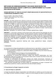
and to verify assumption of axial pile rigidity. Double integration of acceleration signals providesinformation of the penetrative motion of the profile as well as magnitude of displacementamplitude.It can also be justified, but more from a research point of view, to mount accelerometerslaterally/ transversally, (especially on slender piles), with the purpose to study magnitude oflateral motion.With results obtained from above mentioned sensors, it’s possible to calculate: i.) the dynamicsoil resistance along the shaft R s , ii.) the penetration speed v p , iii.) displacement amplitude S p ,iv.) penetrative motion u(t), v.) system efficiency ξ and vi.) verifying that the pile can be treatedlike a rigid body. Sources of how to accomplish this in great detail can be found in (Rao, 1993;Bonita, 2000; <strong>Viking</strong>, 2002).5.4. Soil instrumentationSoil related factors and its instrumentation consist of the following parts.Magnitude of generated ground vibrations can be assessed by using either geo-phones oraccelerometers, (preferably tri-axial geophones/ accelerometers), positioned at different radialdistances (and depths) from the driven pile.Magnitude of induced pore pressure at different depths and radial distances in relation tointended position of pile to be driven. Can be accomplished by installing pore pressure sensorsprior to the pile installation.a.)Sticker glued on the pile for ocular monitoringof the axial displacement amplitude.0 1/8 " 1/4 " 3/8 " 1/2 " 5/8 " 3/4 " 7/8 " 1 "b.)Visualization of the ocular readingsof the axial displacement amplitude.Note: S p= 2s o= 1.0 [in.]s o= 0.5 [in.]s o= 0.5 [in.]Figure 9. Paper sticker for monitoring of the peak-to-peak displacement amplitude.80
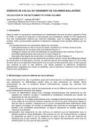
5.5. Other instrumentationThe relative ease (read v p ) of vibratory driving, which is the results of the dynamic equilibrium ofthe vibrator/pile/soil system, can easily be assessed by using a digital camcorder that registersthe time differences of depth marks, (painted on the side of the pile), enters the soil.Figure 9 a schematically illustrates a simple but useful paper sticker, for monitoring the actualpeak-to-peak displacement amplitude S p of the pile as it slides into the ground. The stickers areglued on to the pile at 5-ft intervals and ocular readings of S p are taken as they slide by theobserver. Results of S p can then be plotted versus penetration depth.Furthermore, even though dynamic vibratory pile monitoring is not included in the PDA featuresof today. The authors has concluded that it’s possible to use a PDA analyzer, (<strong>Viking</strong> et al.2004), (however to be used with some caution and modifications). Obtained results can providethe Engineer with a wealth of beneficial information on which to base his/hers decision.REFERENCESABI News Nr. 1/2004, (2004), 8 pp.http://www.abi-gmbh.de/html/abi_-_news_archiv.htmlBarkan, D.D., (1962), "Dynamics of Bases and Foundations" (translated from Russian by L.Drashevska and translation edited by G.P. Tschebotarioff, original title in Russian"Dynamicka Osnovanity I Fundamentov", (1948), Moscow) McGraw-Hill book company Inc.,N.Y., 434 pp.Bernhard, R.K., (1967), "Fluidization phenomena in soils during vibro-compaction and vibropile-drivingand-pulling", Special Report 106, US Army Cold Regions Research andEngineering, Hanover, NH 1967, 58 pp.Bonita, J.A., (2000), "The effects of vibration on the penetration resistance and pore waterpressure in sands", PhD Thesis, Dept. of Civil and Environmental Engineering, VirginiaPolytechnic Inst. and State University.Cudmani, R., (2001), "Static, alternating and dynamic penetration of cohesionless soils",Doctoral Thesis 152, Div. of Soil Mechanics and Foundation Engineering, Univ. of Karlsruhe,Germany, (in German).De Cock, Sébastian., (1998), "Comparison de modèles de vibrofonçage avec des résultats delaboratoire et de chantier", Travail de fin d’études présenté pour l’obtention du dimplômed’ingénieur Civil des Constructions, Dept. AMCO, Univ. Catholique de Louvain, Belgium, pp.113.Dierssens, G., (1994), "Ein bodenmechani-sches modell zur beschreibung des vibrationsrammensin körningen böden", Doctoral Thesis 133, Div. of Soil Mechanics and FoundationEngineering, Univ. of Karlsruhe, Germany, (in German).Holeyman, A., (1993), "HYPERVIB1, An analytical model-based computer program to evaluatethe penetration speed of vibratory driven sheet piles", Research report prepared for BBRI,June -93, 23 pp.Legrand, C., Van Rompaey, D., Menten, J., (1993), "A Comparison of Different Sheet-PileInstallation Methods", Internal research report of BBRI, (obtained through personalcorrespondence).O'Neill Michael W., Vipulanandan, C., Wong, D., (1990), "Laboratory modelling of vibro-drivenpiles", Journal of Geotechnical Engineering, ASCE, Vol. 116, No. 8, pp. 1190-1209.Rao, P.M., (1993), "Effect of pile geometry and soil saturation in the behaviour of nondisplacement piles installed by vibration", MSc Thesis, Dept. of Civil and EnvironmentalEngineering, Univ. of Houston, TX.Rodger, A.A., (1976), "Experimental and theoretical investigation of the parameters influencingthe vibratory penetration of dry cohesionless soils", PhD Thesis, Aberdeen Univ., Aberdeen,Vol. 1, Chapters 1-15, pp. 338.81
Rodger, A.A., Littlejohn, G., (1980), "A study of vibratory driving in granular soils",Geotechnique, Vol. 30, No. 3, pp. 269-293.Stevens, R.F., Wiltsie, E.A., and Turton, T.H. (1982), "Evaluating Pile Drivability for Hard Clay,Very Dense Sand, and Rock", Proceedings, 14th Offshore Technology Conference, Houston,Vol. 1, pp. 465-481.Vanden Berghe, JF., Holeyman, A., (1997), "Comparison of two models to evaluate thebehaviour of a vibratory driven sheet pile", Proceedings, XIth Young Geotechnical EngineersConference, Geotechnical Engineers and Computers, September 24 - 27, 1997, Madrid,Spain, pp. 60-72.Vanden Berghe, JF., Holeyman, A., Juaristi, E., Schmitt, A., (2001), "Interlock Friction in aSheet-pile: laboratory testing", Proceedings, XVth ISSMGE, Aug. 27-31, 2001, Istanbul, Vol.2, pp. 1273-1276.<strong>Viking</strong>, K., Bodare, A., (1998), "Laboratory studies of dynamic shaft resistance response of avibro-driven model pile in granular soil by varying the relative density", Proceedings, XIIECSMGE, Vol. 2, pp. 863-869.<strong>Viking</strong>, K., Bodare, A., (2000), "Full-scale field-test studies on driveability and induced groundvibrations of vibratory driven sheet piles", Proceedings, DFI 25th Annual Members Conf. and8th International Conf., New York, NY USA, Oct. 5-7, 2000, 19 pp.<strong>Viking</strong>, K., Green, J., Nilsson, C-O., (2000) b, "Generated and measured ground vibrationsduring vibro-installation of sheet piles", Proceedings, 13th Nordiska Geoteknikermötet,Helsingfors, June 5-7, 2000, pp. 291-299, (in Swedish).<strong>Viking</strong>, K., (2002), “Vibro-driveability –a field study of vibratory driven sheet piles in noncohesivesoils”, PhD Thesis, Div. of Soil and Rock Mechanics, Royal Inst. of Technology,Stockholm, Sweden. http://media.lib.kth.se/dissengrefhit.asp?dissnr=3358<strong>Viking</strong>, K., Dietel, R., Roberts, T., (2004), "A case study of vibratory pile installation monitoringof a precast prestressed concrete pile", Proceedings, DFI 29th Annual Conference on DeepFoundations, Vancouver, BC, Canada. 2004, pp. 273-281.82