Railscaf Horizontal System
Railscaf Horizontal System
Railscaf Horizontal System

You also want an ePaper? Increase the reach of your titles
YUMPU automatically turns print PDFs into web optimized ePapers that Google loves.
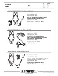
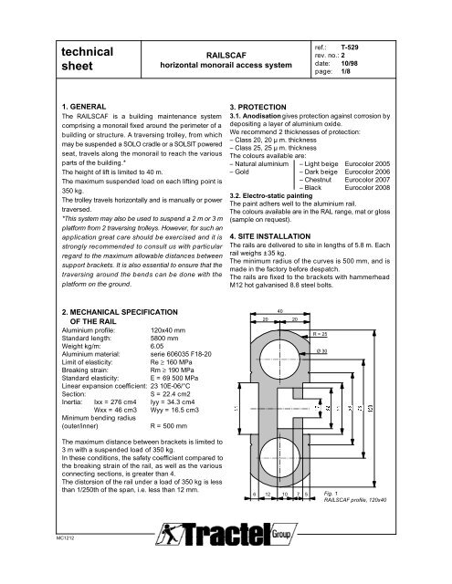
technicalsheetRAILSCAFhorizontal monorail access systemref.: T-529rev. no.: 2date: 10/98page: 1/81. GENERALThe RAILSCAF is a building maintenance systemcomprising a monorail fixed around the perimeter of abuilding or structure. A traversing trolley, from whichmay be suspended a SOLO cradle or a SOLSIT poweredseat, travels along the monorail to reach the variousparts of the building.*The height of lift is limited to 40 m.The maximum suspended load on each lifting point is350 kg.The trolley travels horizontally and is manually or powertraversed.*This system may also be used to suspend a 2 m or 3 mplatform from 2 traversing trolleys. However, for such anapplication great care should be exercised and it isstrongly recommended to consult us with particularregard to the maximum allowable distances betweensupport brackets. It is also essential to ensure that thetraversing around the bends can be done with theplatform on the ground.3. PROTECTION3.1. Anodisation gives protection against corrosion bydepositing a layer of aluminium oxide.We recommend 2 thicknesses of protection:– Class 20, 20 µ m. thickness– Class 25, 25 µ m. thicknessThe colours available are:– Natural aluminium – Light beige Eurocolor 2005– Gold – Dark beige Eurocolor 2006– Chestnut Eurocolor 2007– Black Eurocolor 20083.2. Electro-static paintingThe paint adhers well to the aluminium rail.The colours available are in the RAL range, mat or gloss(sample on request).4. SITE INSTALLATIONThe rails are delivered to site in lengths of 5.8 m. Eachrail weighs ±35 kg.The minimum radius of the curves is 500 mm, and ismade in the factory before despatch.The rails are fixed to the brackets with hammerheadM12 hot galvanised 8.8 steel bolts.2. MECHANICAL SPECIFICATIONOF THE RAILAluminium profile: 120x40 mmStandard length:5800 mmWeight kg/m: 6.05Aluminium material: serie 606035 F18-20Limit of elasticity:Re ≥ 160 MPaBreaking strain:Rm ≥ 190 MPaStandard elasticity: E = 69 500 MPaLinear expansion coefficient: 23 10E-06/°CSection:S = 22.4 cm2Inertia: Ixx = 276 cm4 Iyy = 34.3 cm4Wxx = 46 cm3 Wyy = 16.5 cm3Minimum bending radius(outer/inner)R = 500 mm4020 20R = 25Ø 30The maximum distance between brackets is limited to3 m with a suspended load of 350 kg.In these conditions, the safety coefficient compared tothe breaking strain of the rail, as well as the variousconnecting sections, is greater than 4.The distorsion of the rail under a load of 350 kg is lessthan 1/250th of the span, i.e. less than 12 mm.6121310 7 5Fig. 1RAILSCAF profile, 120x40MC1212
technicalsheetRAILSCAFhorizontal monorail access systemref.: T-529rev. no.: 2date: 10/98page: 2/85. RAIL CONNECTIONS5.1. Fixed connectionThe connection between two rails is by 2 aluminium rods, dia. 30x245 mm, fixed by 8 pins, dia. 3.7x19 mm.This type of connection should be done with a maximum distance of 500 mm from the bracket.245Fig. 2Fixed connecting two rails8 NAILS “3.7X198 CLOUS “3.7X19CODE:4767620 6085 601.520CLOUTAGENAILING2 RONDS “30X2452 RODS “30X245(CODE:62505)Pinning is only done on one side, and in principleon the side facing the facade(i.e. on the bracket side).Pinning machine: DX 36M-HILTIPin: EDN-19-P8-HILTI, dia. 3.7x19, code 47676Cartridge: 6.8/11M-RED-HILTI, code 476861.5FIXED JOINTJONCTION FIXEDetail of fixed connectionCirclips 30x1.5DIN 471 – StainlessCode 156165.2. Expansion connectionsAn expansion connection is fitted after two fix connections (= every 17.40 m). The connection between two railsis by 2 aluminium rods.This type of connection should be done with a maximum distance of 500 mm from the bracket.4 NAILS “3.7X194 CLOUS “3.7X19CODE:4767620 602454 / 56020CLOUTAGENAILING4 / 52 RONDS “30X2452 RODS “30X245(CODE:62505)EXPANSION CONNECTIONCONNECTION DE DILATATION5.3. Connection with 2 fish platesOnly used at the end of a closed travelling track. The connection between two rails is by 2 fish plates 40x8x200.This type of connection should be done with a maximum distance of 500 mm from the bracket.222 234025 45 60 45 25200MC1212
technicalsheetRAILSCAFhorizontal monorail access systemref.: T-529rev. no.: 2date: 10/98page: 3/86. RAIL END STOPOn "open" trackways an end stop (11) must be fitted atthe end of the rails. It is fixed by screws.End limit sensors (12) fitted on the motorised trolley stopthe trolley at the end of the trackway, approaching theend stop.11 1212 11100150Fig. 3 – <strong>Horizontal</strong> monorail with trolley, end stops(11) and end limit sensors (12).7. BRACKETSThe brackets (Fig. 4) which support the rail, arepositioned every 3 m on the straight sections and asset out in figures 7 to 12 for the curved sections. Thebrackets are galvanised or stainless steel.The fixing plate of the bracket itself has a ± 10 mmvertical adjustment.Influence of edge200 200Ø 16Min. hole depthØ 16concrete30N/mm2200 250bracket± 650Réaction 1350 daN1525025 20025350 daNFig. 4<strong>Horizontal</strong> adjustable bracketFixing 3 boltsHST M16x140/25-44521/2 - HILTI (concrete 30N/mm2).Max. tightness 125 Nm.Loading bolt 675 daN.620± 638 17Réaction 1350 daNMC1212
technicalsheetRAILSCAFhorizontal monorail access systemref.: T-529rev. no.: 2date: 10/98page: 4/88. TRAVERSING TROLLEYThe traversing trolley is designed for a solo cradle or SOLSIT powered seat, on a single suspension system, topass around the corners of buildings. On straight parts 2 m or 3 m platforms may be used on two suspension points.The trolley comprises 2 travelling rollers and 1 guide roller, fitting around the rail. The rollers have a polyurethanetread to prevent wear to the rail.The casing of the trolley is in stainless steel.The trolley is either manually or power traversed.8.1. Manual traversing trolley by endless rope (Fig. 5)Generally, a manual traversing trolley is sufficient, since the effort required to traverse the trolley is low.Weight: 18 kg. Code for complete manual trolley: 21438.84 53153drive rollerfree roller48 8223guide rollerFig. 5Manualtraversingtrolleynylon rope68.5270safety wire rope,fixing depending onthe type of cradle(see fig. 5.1)lifting wire rope2 wire ropeanchoring pinsmonoALTA "L"Fig. 5.1 - Arrangement of the lifting and safety wire ropeson the mono cradle or with two suspension points.MC1212
technicalsheetRAILSCAFhorizontal monorail access systemref.: T-529rev. no.: 2date: 10/98page: 5/88.2. Powered trolley (Fig. 6)The trolley is powered using a completely enclosed geared motor with brake; level of protection IP 54, Class Finsulation, suitable for use in tropical conditions. 3 phase 220/380 V or 240/415 V, 50 Hz.Controls by push-button pendant including UP/DOWN and Emergency Stop.Weight: 24 kg. Code for complete powered trolley: 21448.270limit sensorgeared motordrive roller4050122.5free rollersguide rollerBA140Fig. 6Powered trolley68.5safety wire rope,fixing A or B dependingon type of cradle(see fig. 5.1)lifting wire rope2 wire ropeanchor pins350 daNmonoALTA "L"Fig. 6.1 - Arrangement of the lifting and safety wire ropeson the mono cradle or with two suspension points.MC1212
technicalsheetRAILSCAFhorizontal monorail access systemref.: T-529rev. no.: 2date: 10/98page: 6/89. SEVERAL EXAMPLES OF APPLICATIONS1000 MAXI3000 MAXI 3000 MAXI 3000 MAXI850 MINI 2000 MINI500 MAXI 500 MAXI0 MINI 0 MINITRONCON DROITSTRAIGHT SECTIONCOURBE 90°CURVE 90°SUPPORT2 BRACKET 3JONCTION/JEU 1.5mmCONNECTION/PLAY 1.5mm350 MAXI200 MINI1JONCTION/JEU 1.5mmCONNECTION/PLAY 1.5mmJONCTION POSSIBLESUR 3 OU 4 SUPPORTSPOSSIBILITY OFCONNECTION ON3 OR 4 BRACKETSConnections only in sections shown by squared area.Curved on 3 or 4 supports without intermediate connection.Straight section on 2 supports without intermediate connection.Fig. 790° curveexternal bending.Length: 5800 mm max.SENS DE CINTRAGEBENDING DIRECTION6501650 MAXI1250 MINISUPPORTBRACKET2 3JONCTION/JEU 1.5mmCONNECTION/PLAY 1.5mmTRONCON DROITSTRAIGHT SECTIONCOURBE 90°CURVE 90°500 MAXI 500 MAXI0 MINI 0 MINI1000 MAXI 3000 MAXI 3000 MAXI 3000 MAXI600 MINI 2000 MINI1Connections only in sections shown by squared area.Curved on 3 or 4 supports without intermediate connection.Straight section on 2 supports without intermediate connection.JONCTION/JEU 1.5mmCONNECTION/PLAY 1.5mmJONCTION POSSIBLESUR 3 OU 4 SUPPORTSPOSSIBILITY OFCONNECTION ON3 OR 4 BRACKETSFig. 890°curveinternal bending.Length: 5800 mm max.SENS DE CINTRAGEBENDING DIRECTION650MC1212
technicalsheetRAILSCAFhorizontal monorail access systemref.: T-529rev. no.: 2date: 10/98page: 7/8TRONCON DROITSTRAIGHT SECTIONJONCTION/JEU 1.5mmCONNECTION/PLAY 1.5mmSUPPORTBRACKETCOURBE < 90°CURVE < 90°SENS DE CINTRAGEBENDING DIRECTIONJONCTION/JEU 1.5mmCONNECTION/PLAY 1.5mmJONCTION POSSIBLESUR 3 OU 4 SUPPORTSPOSSIBILITY OFCONNECTION ON3 OR 4 BRACKETSConnections only in sections shown by squared area.Curved on 3 or 4 supports without intermediate connection.Straight section on 2 supports without intermediate connection.Fig. 9
technicalsheetRAILSCAFhorizontal monorail access systemref.: T-529rev. no.: 2date: 10/98page: 8/8TRONCON DROITSTRAIGHT SECTION500 MAXI0 MINI436 MAXI433 433 698 MAXI 2619 MAXI3000 MAXI 3000 MAXI286 MINI100 MINI 2000 MINIJONCTION/JEU 1.5mmCONNECTION/PLAY 1.5mm500 MAXI0 MINITRONCON DROITSTRAIGHT SECTION1 2COURBE 2X60°SUR 1+2+3+434JONCTION/JEU 1.5mmCONNECTION/PLAY 1.5mm350 MAXI200 MINI1650 MAXI902 MINISUPPORTBRACKETSENS DE CINTRAGE EXTER.OUTER BENDING DIRECTIONSENS DE CINTRAGE INTER.INNER BENDING DIRECTIONConnections only in sections shown by squared area.Curved on 3 or 4 supports without intermediate connection.Straight section on 2 supports without intermediate connection.Fig. 11 - 2 x 60° for horizontal profile.external and internal bending.Length - curved or straight section: 5800 mm max.500 MAXI1000 MAXI 1000 MAXI3000 MAXI 2230 MAXI 3000 MAXI2000 MINI850 MINI 600 MINIJONCTION/JEU 1.5mmCONNECTION/PLAY 1.5mmTRONCON DROITSTRAIGHT SECTION1350 MAXI200 MINICOURBE 2X90°SUR 1+2+3+42500 MAXI0 MINITRONCON DROITSTRAIGHT SECTION6503JONCTION/JEU 1.5mmCONNECTION/PLAY 1.5mmSUPPORT/BRACKET1650 MAXI1250 MINISENS DE CINTRAGE EXTER.OUTER BENDING DIRECTIONSENS DE CINTRAGE INTER.INNER BENDING DIRECTIONConnections only in sections shown by squared area.Curved on 3 or 4 supports without intermediate connection.Straight section on 2 supports without intermediate connection.Fig. 12 - 2 x 90° for horizontal profile.external and internal bending.Length - curved or straight section: 5800 mm max.MC1212