SKF 6229EN aktuell
SKF 6229EN aktuell
SKF 6229EN aktuell

Create successful ePaper yourself
Turn your PDF publications into a flip-book with our unique Google optimized e-Paper software.
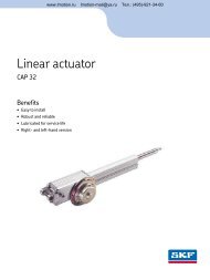
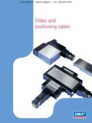
www.lmotion.ru skf@lmotion.ru Тел. (495)-921-34-60Profile rail guides
www.lmotion.ru skf@lmotion.ru Тел. (495)-921-34-60ContentThe <strong>SKF</strong> ® brand now stands for morethan ever before, and means more toyou as a valued customer.While <strong>SKF</strong> maintains its leadershipas the hallmark of quality bearingsthroughout the world, new dimensionsin technical advances, product supportand services have evolved <strong>SKF</strong> intoa truly solutions-oriented supplier,creating greater value for customers.These solutions encompass ways tobring greater productivity to customers,not only with breakthrough applicationspecificproducts, but also throughleading-edge design simulation toolsand consultancy services, plant assetefficiency maintenance programmes,and the industry’s most advancedsupply management techniques.The <strong>SKF</strong> brand still stands for the verybest in rolling bearings, but it nowstands for much more.<strong>SKF</strong> – the knowledge engineeringcompanyGeneral information3 Introduction4 Product overview6 Technical data6 Preload classes6 Speed6 Acceleration6 Temperature7 Friction7 Seals7 Scraper plates8 Load rating8 Definition of the basic dynamic load rating8 Definition of the basic static load rating8 Definition and calculation of the basic rating life8 Dynamic equivalent bearing load for calculation of the service life9 Dynamic equivalent bearing load9 Static equivalent bearing loadAccuracy10 Accuracy classes11 Selection criteria for combination of accuracy classes12 Preloading and stiffnessCarriages14 Load ratings - Quick selection18 Accuracy classes, dimensions and designationsStandard rails35 Product overview36 Accuracy classes, dimensions and designationsOrdering key40 Ordering keyAccessories43 Product overview44 Standard carriages44 Scraper plates45 Seals46 Lubrication48 Bellows50 Cover stripMounting instructions54 General mounting instructionsMaintenance and lubrications62 Maintenance and lubrications
Generalwww.lmotion.ru skf@lmotion.ru Тел. (495)-921-34-60IntroductionAs the world’s leading manufacturerof rolling bearings, <strong>SKF</strong> suppliespractically every type of rolling bearingfor rotary and linear movements.The standard profile rail guides producedby <strong>SKF</strong> are brought togetherin this catalogue. <strong>SKF</strong> profile railguides are accuracy rolling bearingsfor linear movements and are thereforesuitable for use in most types ofmachinery. With these profile railguides it is possible for <strong>SKF</strong> to offera guide system which achieves agood price/performance ratio.Profile rail guides from <strong>SKF</strong> areavailable in many designs and sizes,and thanks to their unlimited strokethey can be adapted to any linearmovement. They consist of a railguide with ground raceways on whichone or several guide carriages canbe moved with an unlimited stroke.The guide carriages are made oftempered bearing steel into whichthe hardened raceways of the ballcircuits are inserted. Fixing holes inthe attachment surfaces enablemachine parts to be directly mountedonto the carriages. Fundamentally,profile rail guides constitute a coupledangular ball bearing in back-tobackarrangement and, dependingon the application, are available indifferent preload classes. The racewaysof the profile rail and of thecarriage are arranged at an angle of45°. As a result, the system has thesame load capacity in the four mainload directions as well as a highmoment load capacity.Depending on the load conditionsand the required service life, aselection can also be made betweentwo design versions. In addition tothe standard carriage length, aseries with extended carriages isavailable which exhibits higher loadrating. To meet the requirements ofoperating practice, a range of differentguide systems is offered. Theirmain features are load capacity,screw connections to provide thefastening points on the carriage andthe sectional height.Thanks to the modular design ofthe systems, subsequent changesare not a problem. This cataloguebrings together all the data whichwe feel is relevant.If you require additional informationplease get in touch with one ofour sales companies.3
www.lmotion.ru skf@lmotion.ru Тел. (495)-921-34-60Product overview• Carriages with and withoutball chain• High load capacities in all maindirections and high momentload capacities• High dynamic performances:v = 5 m/s; a max = 500 m/s 2• Low noise and smooth, lightrunning due to optimised ballrecirculation and ideal ballchain geometry• Long term lubrication system• Lube ports with metal threadson all sides.• Various accuracy and preloadclasses• Carriages can be screwed fromabove or below, depending ontype.• Improved stiffness under lift offand side loading conditions whenadditional mounting screws areused for the holes in the centre ofthe carriage• Integrated all-round sealingthrough front and longitudinalseals• Wide range of accessories• Both grease and oil lubricationpossible despite initial greaseapplication• Wide range of accessories• Worldwide <strong>SKF</strong> service network• Both sides of the guide rail can beused as reference edges• Full interchangeability due tostandardised rail, with orwithout rail seal cover strip,for all carriage versions4
www.lmotion.ru skf@lmotion.ru Тел. (495)-921-34-60LLRHC xx SAFlange short. Standard height.LLRHC xx AFlange normal. Standard height.LLRHC xx LAFlange long. Standard height.LLRHC xx RSlim line normal. High.Ball chainOptimises noise level and runningbehaviourLLRHC xx LRSlim line long. High.LLRHC xx SUSlim line short. Standard height.LLRHC xx USlim line normal. Standard height.LLRHC xx LUSlim line long. Standard height.5
www.lmotion.ru skf@lmotion.ru Тел. (495)-921-34-60Technical dataGeneral informationThe general technical data applies toall rail guides (all carriages andrails).Special technical data is listedseparately for the individual designs.Preload classesIn view of the different user requirements,the ball rail guides can besupplied in four different preloadclasses.So as not to reduce the servicelife, the preload should not amountto more than 1/3 of the bearingload F.In general, the stiffness of thecarriage increases according to thepreload increase.Guide systems withparallel rails• In connection with the selectedpreload class the permissibledeviation in parallelism of therails must also be taken intoaccount (see tables for thevarious designs).• For the installation of rail guides inthe accuracy class P5 werecommend the version withclearance T0 or the preloadclass T1 in order to avoidstresses owing to thetolerances.Speedv max : 5 m/sAccelerationa max : 500 m/s 2Only in the case of preloaded systems.In the case of non-preloaded systems:a max = 50 m/s 2Material specifications1 Recirculation parts:POM (PA6.6)2 Lubrication nipple:carbon steel3 Metal front plates:1.43014 Seals: TEE-E5 Flange screws:carbon steel123Temperatureresistancet max : 100 °CThis is a maximum value which isonly permissible for a short time. Incontinuous operation a maximumtemperature of 80 °C must not beexceeded.6 Thread pins: 1.43017 Balls: bearing steel8 Housing: tempered steel9 Cover strip retainingclamps: aluminium10 Clamping screw and nut:1.430111 Rail: tempered steel12 Cover strip: 1.4301978111012 4 566
www.lmotion.ru skf@lmotion.ru Тел. (495)-921-34-60FrictionThe friction coefficient µ of the ballrail guide is approx. 0,002 to 0,003(not including the friction of the seal).As a result of the design with 4ball rows a 2-point contact exists forall load directions. This reduces frictionto a minimum (Fig. 1).Fig. 1SealsSeals should prevent the penetrationof dirt and chips into the interior ofthe carriage in order to avoid prematurefailure.Universal sealUniversal seals are installed as standardin <strong>SKF</strong> carriages.They have a constant sealingeffect on rails with and withoutcover strip.In addition to efficient sealing, thedesign also provides for low friction.For applications where low frictionis required light-contact seals areavailable on request.Scraper platesScraper plates can be ordered asaccessories (have to be attachedby the customer).They are suitable for use in mostenvironments where coarse dirt orchips are encountered.Front sealFront seals can be ordered as accessoriesand are attached by the customer.They are suitable for use inenvironments with fine dust ormetal particles, as well as coolantsor cutting fluids.Note!For extreme duty in environmentswith coarse dirt or metal particles,or where there is massive use ofcoolants or cutting fluids, Viton sealsare available on request.Viton seals have to be attachedby the customer.7
www.lmotion.ru skf@lmotion.ru Тел. (495)-921-34-60Load ratingDefinition of the basicdynamic load rating CThe radial load, constant in magnitudeand direction, which a linearrolling bearing can in theory accommodatefor a basic rating life representedby a travelled distance of10 5 m (to DIN 636 Part 1).The basic dynamic load ratings inthe tables are generally 30 % higherthan the values to DIN. They havebeen verified in tests.Definition of the basicstatic load rating C 0The static load in the direction ofloading which corresponds to a calculatedload in the centre of themost highly loaded contact pointbetween the rolling element and bothraceways (rail) at an osculation of≤ 0,52, 4 200 MPa.Note:At this load on the contact point apermanent total deformation of therolling element and raceway occurswhich corresponds to about 0,0001times the rolling element diameter(to DIN 636 Part 2).Definition and calculationof the basic ratinglifeThe calculated life achievable with90 % reliability for a single rollingbearing or a group of evidentlyidentical rolling bearings runningunder identical conditions given thematerial generally used today ofnormal manufacturer’s quality andusual operating conditions (to DIN636 Part 1).Basic rating life at constant speedThe basic rating life L or L h can becalculated applying the formula (1),(2) or (3):(1)L 10L 10hCPsnDynamic equivalentbearing load for calculationof the service lifeL 10 = ( ) 3 10 5v mv 1 ,v 2 ...v nt 1 ,t 2 ...t nCP= basic rating life (m)= basic rating life (h)= basic dynamic loadrating (N)= equivalent load (N)= stroke length (m)= stroke frequency(double strokes/min)= mean speed (m/min)= travel speeds (m/min)= time proportions forv 1 , v 2 ...v n (%)The formulae for calculating theservice life of profile rail guidesapply to a stroke length of S ≥ 2times the carriage length. At lowervalues the load rating is reduced.Please consult <strong>SKF</strong>.For a fluctuating bearing load thedynamic equivalent loading F is calculatedaccording to formula (5):L(2) L 10h =10F3 13 ¥ s 1 + F 23 ¥ s 2 + ... + F n3 ¥ s n2 ¥ s ¥ n ¥ 60(5) F m =sL load (N)(3) L 10h = 1060 ¥ v mF 1 , F 2 . . . F n = constant loadsBasic rating life at changing speedF m= constant meanduring strokelengths s 1 , + s 2 +,(4) v m = t 1 ¥ v 1 + t 2 ¥ v 2 + ... + t n ¥ v n100....s n (N)s= total strokelength (s = s 1 +s 2 +, ....+ s n ),during whichloads F 1 , F 2 ... F nhave an effect (mm)• given a combined bearing loadNote on dynamic loadcapacities and momentsDetermination of dynamic loadcapacities and moments is based ona travel life of 100 000 m. However,frequently this is determined on thebasis of only 50 000 m. In this casefor comparison: multiply values C, M Cand M A by 1.26 in accordance with<strong>SKF</strong> tables.For carriages with ball chain thepermissible moments are reduced inaccordance with the load ratings.8
www.lmotion.ru skf@lmotion.ru Тел. (495)-921-34-60MMF VF VF V0F HF HF H0Dynamic equivalentbearing loadFor a combined external load – verticaland horizontal – the dynamicequivalent load F is calculated bymeans of formula (6):(6)F= |F V | + |F H |dynamic equivalent load (N)F V = dynamic external load,vertical (N)F H = dynamic external load,horizontal (N)Note:If different load stages exist for F Vand F H , F V and F H must be calculatedindividually using formula (5). Anexternal load applied at any angle tothe carriage must be divided intothe proportions F V and F H . Theamounts are then used in formula (6)Dynamic equivalentbearing loadFor a combined external load – verticaland horizontal – in combinationwith a torsional moment the dynamicequivalent load F can be calculatedusing formula (7):(7) F= |F V | + |F H | + C ¥ |M|FF V , F HMCM tM t= dynamic equivalentload (N)= dynamic externalloads (N)= dynamic torsionalmoment (Nm)= basic dynamic loadrating (N)= dynamic permissiblemoment (Nm)Formula (7) only applies if a singlerail is used.Note: The design of the ball rail guidepermits this simplified calculation.Note:If different load stages exist for F Vand F H , F V and F H must be calculatedindividually using formula (5). Anexternal load applied at any angle tothe carriage must be divided into theproportions F V and F H The amountsare then used in formula (7).Static equivalentbearing loadFor a combined external static load– vertical and horizontal – in connectionwith a static torsionalmoment the static equivalent load F 0can be calculated using formula (8).The static equivalent load F 0 mustnot exceed the static load rating C 0 .Formula (8) only applies if a singlerail is used.F 0 = |F V0 | + |F H0 | + C 0 ¥ |M 0|(8)M t0F 0 = static equivalentload (N)F V0 , F H0 = static externalloads (N)M 0 = static torsionalmoment (Nm)C 0 = basic static loadrating (N)M t0 = static permissiblemoment (Nm)Note:An external load applied at anyangle to the carriage must be dividedinto the proportions F V0 and F H0 .The amounts are then used in formula(8).9
Accuracywww.lmotion.ru skf@lmotion.ru Тел. (495)-921-34-60Accuracy classesAccuracy classes andtheir tolerances<strong>SKF</strong> profile rail guides are availablein five accuracy classes. As shown inthe adjacent illustration, the tolerancesare defined for each accuracyclass. The stated accuracy classesare available for almost all types ofprofile rail guides. For the designswhich can be supplied please referto the respective table on page 11.Problem-free interchangeabilitythroughprecision manufactureThe rail and carriage are producedso precisely by <strong>SKF</strong>, especially in theball raceway area, that each individualelement can be exchanged atany time.For example, a carriage can beused without any problems on differentrails of the same size.Conversely, various carriages canbe used on one rail.Dimensional tolerance in height “H”The dimensional tolerance in height“H” is the maximum deviation of theheight “H” for the carriages on aprofile rail (Fig. 2).Dimensional tolerance in width “N”The dimensional tolerance in width“N” is the maximum deviation of the“N” dimension for the carriages on aprofile rail (Fig. 2).• The “N” dimension designates thedistance of the mounting surfaceof the profile rail from the groundside surface of the carriage.• The accuracies stated are meanvalues and relate to the centre ofthe carriage.• The tolerances should be checkedagain after the profile rail guidehas been mounted on the machinebed.Fig. 1Accuracy class Tolerance Max. differences in dimensionH and N on one railH (µm) N (µm) D H (µm) D N (µm)P5 ± 100 ± 40 30 30P3 ±40 ±20 15 15P1 ±20 ±10 7 7P01 ±10 ±7 5 5P001 ±5 ±5 3 3Measured inthe centre ofthe carriage:For any combinationof carriages and railsover the entire raillengthFor different carriages atthe same rail position* Tolerances for the combination of different accuracy classes in respectof carriage and rail can be referred to on page 11.Fig. 2Fig. 350H P 1P 1NP 1P1 Deviation in parallelism (µm)40302010001 000 2 000 3 000 4 000 5 000L (rail length, mm)P5P3P1P01P0016 00010
www.lmotion.ru skf@lmotion.ru Тел. (495)-921-34-60Selection criteria for combination of accuracy classesRails P5 P3 P1 P01 P001Carriages µm µm µm µm µmTolerance dimension H (µm) ± 100 ± 48 ± 32 ± 23 ± 19P5 Tolerance dimension N (µm) ± 40 ± 28 ± 22 ± 20 ± 19Max. difference of dimensions H and N on a rail (µm) 30 30 30 30 30Tolerance dimension H (µm) ± 88 ± 40 ± 23 ± 23 ± 19P3 Tolerance dimension N (µm) ± 33 ± 20 ± 14 ± 20 ± 19Max. difference of dimensions H and N on a rail (µm) 15 15 15 15 15Tolerance dimension H (µm) ± 84 ± 34 ± 21 ± 11 ± 7P1 Tolerance dimension N (µm) ± 28 ± 16 ± 10 ± 8 ± 7Max. difference of dimensions H and N on a rail (µm) 7 7 7 7 7Tolerance dimension H (µm) ± 83 ± 33 ± 19 ± 10 ± 6P01 Tolerance dimension N (µm) ± 27 ± 15 ± 9 ± 7 ± 6Max. difference of dimensions H and N on a rail (µm) 5 5 5 5 5Tolerance dimension H (µm) ± 82 ± 32 ± 18 ± 9 ± 5P001 Tolerance dimension N (µm) ± 26 ± 14 ± 8 ± 6 ± 5Max. difference of dimensions H and N on a rail (µm) 3 3 3 3 3Recommendations forthe combination ofaccuracy classesRecommended for short strokes andsmall distances between the carriages:Carriage in higher accuracy classthan guide rail.Recommended for long strokesand larger distances between thecarriages:Guide rail in higher accuracy classthan carriage.Running accuracy asselection criterionBy means of perfected ball entryand exit zones in the carriages ofaccuracy classes P1 and P001, ahitherto unattained running accuracyaccompanied by extremely low pulsationis achieved.This is particularly suitable forultra-fine metal cutting operations,metrology, high-precision scanners,erosion techniques etc.11
www.lmotion.ru skf@lmotion.ru Тел. (495)-921-34-60Preloading and stiffnessFor perfect operating behaviourunder various operating conditionsin an extremely wide range of applicationsit is necessary to establishthe suitable preload. In general, aslight to medium preload is enoughfor the majority of applications. Forspecial applications in which highshock loads and vibration can occurit is advisable to use a higher preloading.The preload classes offeredby <strong>SKF</strong> are categorised in Table 4.Selection of thepreload classIn the designs with clearance nopreloading is achieved. Instead, thereis clearance of between 1 and 10µm between the carriage and rail. Iftwo rails and more than one carriageper rail are used this clearanceis in most cases equalised by parallelismtolerances.Preload force referred to the basicdynamic load rating Cdyn of therespective carriage.Example:Carriage LLRHC 35 AC = 41 900 NPreload 0,02 x C = 838 NThis carriage is preloaded with abasic load of approx. 838N.Table 4Versions and area of applicationsT0 – ClearanceFor particularly smooth-running guide systems with low frictionand low external influences. Designs with clearance areonly available in the accuracy classes P5 and P3.T1 - Preload 0,02 CFor precise guide systems with low external load and highrequirements in respect of overall stiffness.T2 - Preload 0,08 CFor precise guide systems with high external load and highrequirements in respect of overall stiffness; also recommendedfor single-rail systems. Above-average moment loads areabsorbed without any significant elastic deformation. At onlymedium moment loads the overall stiffness is furtherimproved.T3 - Preload 0,13 CFor highly rigid guide systems such as precision machine toolsor injection mould clamping units. Above-average loads andmoments are absorbed with lowest-possible elastic deformation.Version with preload T3 only available in accuracy classesP1, P01 and P001.12
www.lmotion.ru skf@lmotion.ru Тел. (495)-921-34-60Deflection as a function ofpreload class and carriage60Example:Carriage LLRHC 35 A,a) Preload 0,02 C (T1)b) Preload 0,08 C (T2)c) Preload 0,13 C (T3)50403020100abc0 55000 1000015000 20000 250006050Example:Carriage LLRHC 35 LA,a) Preload 0,02 C (T1)b) Preload 0,08 C (T2)c) Preload 0,13 C (T3)4030201000 55000 1000015000 20 20000 25 25000abcExample:Carriage LLRHC 35 U,a) Preload 0,02 C (T1)b) Preload 0,08 C (T2)c) Preload 0,13 C (T3)60504030201000 55000 1000015000 20000 25000abcExample:Carriage LLRHC 35 LU,a) Preload 0,02 C (T1)b) Preload 0,08 C (T2)c) Preload 0,13 C (T3)Legenddel. = elastic deformationF = load6050403020100abc0 55000 1000015000 20000 2500013
Carriageswww.lmotion.ru skf@lmotion.ru Тел. (495)-921-34-60Load ratingsLLRHC xx SA (Flange short. Standard height.)Size 15 20 25 30 35 45Designball chain C (N) 5 900 12 400 14 000 22 100 29 300 –no ball chain C (N) 6 800 12 400 15 800 22 100 29 300 –ball chain C 0 (N) 6 700 13 600 15 200 24 800 32 400 –no ball chain C 0 (N) 8 100 13 600 18 200 24 800 32 400 –LLRHC xx A (Flange normal. Standard height.)Size 15 20 25 30 35 45Designball chain C (N) 7 280 17 400 21 300 29 300 41 900 63 300no ball chain C (N) 7 800 18 800 22 800 31 700 41 900 68 100ball chain C 0 (N) 12 100 21 700 27 300 37 200 54 000 77 100no ball chain C 0 (N) 13 500 24 400 30 400 41 300 54 000 85 700LLRHC xx LA (Flange long. Standard height.)Size 15 20 25 30 35 45Designball chain C (N) 9 000 23 100 27 500 38 000 53 000 81 900no ball chain C (N) 10 000 24 400 30 400 40 000 55 600 90 400ball chain C 0 (N) 17 500 32 500 39 500 53 700 75 600 111 400no ball chain C 0 (N) 20 200 35 200 45 500 57 800 81 000 128 50014
www.lmotion.ru skf@lmotion.ru Тел. (495)-921-34-60LLRHC xx SU (Slim line short. Standard height.)Size 15 20 25 30 35 45Designball chain C (N) 5 900 12 400 14 000 22 100 29 300 –no ball chain C (N) 6 800 12 400 15 800 22 100 29 300 –ball chain C 0 (N) 6 700 13 600 15 200 24 800 32 400 –no ball chain C 0 (N) 8 100 13 600 18 200 24 800 32 400 –LLRHC xx U (Slim line normal. Standard height.)Size 15 20 25 30 35 45Designball chain C (N) 7 280 17 400 21 300 29 300 41 900 63 300no ball chain C (N) 7 800 18 800 22 800 31 700 41 900 68 100ball chain C 0 (N) 12 100 21 700 27 300 37 200 54 000 77 100no ball chain C 0 (N) 13 500 24 400 30 400 41 300 54 000 85 700LLRHC xx LU (Slim line long. Standard height.)Size 15 20 25 30 35 45Designball chain C (N) 9 000 23 100 27 500 38 000 53 000 81 900no ball chain C (N) 10 000 24 400 30 400 40 000 55 600 90 400ball chain C 0 (N) 17 500 32 500 39 500 53 700 75 600 111 400no ball chain C 0 (N) 20 200 35 200 45 500 57 800 81 000 128 50015
www.lmotion.ru skf@lmotion.ru Тел. (495)-921-34-60LLRHC xx R (Slim line normal. High.)Size 15 25 30 35 45Designball chain C (N) 7 280 21 300 29 300 41 900 63 300no ball chain C (N) 7 800 22 800 31 700 41 900 68 100ball chain C 0 (N) 12 100 27 300 37 200 54 000 77 100no ball chain C 0 (N) 13 500 30 400 41 300 54 000 85 700LLRHC xx LR (Slim line long. High.)Size 25 30 35 45Designball chain C (N) 27 500 38 000 53 000 81 900no ball chain C (N) 30 400 40 000 55 600 90 400ball chain C 0 (N) 39 500 53 700 75 600 111 400no ball chain C 0 (N) 45 500 57 800 81 000 128 500Note on dynamic load capacities and momentsDetermination of dynamic load capacities and moments is based on a travel life of100 000 m. However, frequently this is determined on the basis of only 50 000 m.In this case for comparison: multiply values C, M C and M A by 1.26 in accordance with<strong>SKF</strong> tables.For carriages with ball chain the permissible moments are reduced in accordance withthe load ratings.16
Notes www.lmotion.ru skf@lmotion.ru Тел. (495)-921-34-6017
www.lmotion.ru skf@lmotion.ru Тел. (495)-921-34-60Accuracy classes, dimensions and designationsCarriage LLRHC xx SAFlange short. Standard height.For type designation seedesignation systemDynamic valuesSpeed v max = 5 m/sAcceleration a max = 500 m/s 2 Size Accuracy class Type designation incl. preload classT0T115 P5 LLRHC 15 SA T0 P5 LLRHC 15 SA T1 P5P3 LLRHC 15 SA T0 P3 LLRHC 15 SA T1 P320 P5 LLRHC 20 SA T0 P5 LLRHC 20 SA T1 P5P3 LLRHC 20 SA T0 P3 LLRHC 20 SA T1 P325 P5 LLRHC 25 SA T0 P5 LLRHC 25 SA T1 P5P3 LLRHC 25 SA T0 P3 LLRHC 25 SA T1 P330 P5 LLRHC 30 SA T0 P5 LLRHC 30 SA T1 P5P3 LLRHC 30 SA T0 P3 LLRHC 30 SA T1 P335 P5 LLRHC 35 SA T0 P5 LLRHC 35 SA T1 P5P3 LLRHC 35 SA T0 P3 LLRHC 35 SA T1 P318
www.lmotion.ru skf@lmotion.ru Тел. (495)-921-34-60a)a) For O-ringSize 15: † 4 x 1,0 (mm)Size 20-35: † 5 x 1,0 (mm)Open lubrication hole as required.See additional elements:Mounting of lubrication adapter.b)b) Lubrication nipple size 15 and 20: Funnel-type nippleType A – Thread size M3 x 5, DIN 3405B2 = 1,6 mmWhen using other nipples, the max. permissible screw depth of 5 mmmust be observed!Size 25 to 35: M6 x 8, DIN 71412B2 = 9,5 mmWhen using other nipples, the max. permissible screw depth of 8 mmmust be observed!Lubrication nipple supplied along with the rail guide (unmounted).Connection possible at all sides.If pin holes are needed, please refer to section "Mounting instructions".Size Dimensions (mm)W 1 A 1 W N L 1 L 2 H H 11)H 42)H 4 H 3 W 2 W 3 H 5 L 6 L 4 H 8 H 915 47 23,5 15 16,0 44,7 25,7 24 19,90 16,30 16,20 5,0 38 24,55 6,70 16,25 17,85 3,20 3,2020 63 31,5 20 21,5 57,3 31,9 30 25,35 20,75 20,55 6,0 53 32,50 7,30 22,95 22,95 3,35 3,3525 70 35,0 23 23,5 67,0 38,6 36 29,90 24,45 24,25 7,5 57 38,30 11,50 25,35 26,50 5,50 5,5030 90 45,0 28 31,0 75,3 45,0 42 35,35 28,55 28,35 7,0 72 48,40 14,60 28,80 30,50 6,05 6,0535 100 50,0 34 33,0 84,9 51,4 48 40,40 32,15 31,85 8,0 82 58,00 17,35 32,70 34,20 6,90 6,90 1)1)Dimension H 4 with cover strip.2)Dimension H 4 without cover stripSize Dimensions (mm) WeightLoad ratings (N) Moments (N m )C C 0 M C M C0 M A M BN 1±0,5H 7 d 4 S 2 d 3 M 2 (kg) dyn. stat. dyn. stat. dyn. stat.15 5,2 10,3 4,3 M5 4,4 M2,5-3,5 depth 0,15 5 400 8 100 52 80 19 2820 7,7 13,2 5,3 M6 6,0 M3-5 depth 0,30 12 400 13 600 150 170 52 5825 9,3 15,2 6,7 M8 7,0 M3-5 depth 0,50 15 900 18 200 230 260 82 9430 11,0 17,0 8,5 M10 9,0 M3-5 depth 0,80 22 100 24 800 380 430 133 15035 12,0 20,5 8,5 M10 9,0 M3-5 depth 1,20 29 300 32 400 640 700 200 22019
www.lmotion.ru skf@lmotion.ru Тел. (495)-921-34-60Carriage LLRHC xx AFlange normal. Standard height.For type designation seedesignation systemDynamic valuesSpeed v max = 5 m/sAcceleration a max = 500 m/s 2Size Accuracy class Type designation incl. preload classT0 T1 T2 T315 P5 LLRHC 15 A T0 P5 LLRHC 15 A T1 P5 LLRHC 15 A T2 P5P3 LLRHC 15 A T0 P3 LLRHC 15 A T1 P3 LLRHC 15 A T2 P3P1 LLRHC 15 A T1 P1 LLRHC 15 A T2 P1 LLRHC 15 A T3 P1P01 LLRHC 15 A T1 P01 LLRHC 15 A T2 P01 LLRHC 15 A T3 P01P001 LLRHC 15 A T1 P001 LLRHC 15 A T2 P001 LLRHC 15 A T3 P00120 P5 LLRHC 20 A T0 P5 LLRHC 20 A T1 P5 LLRHC 20 A T2 P5P3 LLRHC 20 A T0 P3 LLRHC 20 A T1 P3 LLRHC 20 A T2 P3P1 LLRHC 20 A T1 P1 LLRHC 20 A T2 P1 LLRHC 20 A T3 P1P01 LLRHC 20 A T1 P01 LLRHC 20 A T2 P01 LLRHC 20 A T3 P01P001 LLRHC 20 A T1 P001 LLRHC 20 A T2 P001 LLRHC 20 A T3 P00125 P5 LLRHC 25 A T0 P5 LLRHC 25 A T1 P5 LLRHC 25 A T2 P5P3 LLRHC 25 A T0 P3 LLRHC 25 A T1 P3 LLRHC 25 A T2 P3P1 LLRHC 25 A T1 P1 LLRHC 25 A T2 P1 LLRHC 25 A T3 P1P01 LLRHC 25 A T1 P01 LLRHC 25 A T2 P01 LLRHC 25 A T3 P01P001 LLRHC 25 A T1 P001 LLRHC 25 A T2 P001 LLRHC 25 A T3 P00130 P5 LLRHC 30 A T0 P5 LLRHC 30 A T1 P5 LLRHC 30 A T2 P5P3 LLRHC 30 A T0 P3 LLRHC 30 A T1 P3 LLRHC 30 A T2 P3P1 LLRHC 30 A T1 P1 LLRHC 30 A T2 P1 LLRHC 30 A T3 P1P01 LLRHC 30 A T1 P01 LLRHC 30 A T2 P01 LLRHC 30 A T3 P01P001 LLRHC 30 A T1 P001 LLRHC 30 A T2 P001 LLRHC 30 A T3 P00135 P5 LLRHC 35 A T0 P5 LLRHC 35 A T1 P5 LLRHC 35 A T2 P5P3 LLRHC 35 A T0 P3 LLRHC 35 A T1 P3 LLRHC 35 A T2 P3P1 LLRHC 35 A T1 P1 LLRHC 35 A T2 P1 LLRHC 35 A T3 P1P01 LLRHC 35 A T1 P01 LLRHC 35 A T2 P01 LLRHC 35 A T3 P01P001 LLRHC 35 A T1 P001 LLRHC 35 A T2 P001 LLRHC 35 A T3 P00145 P5 LLRHC 45 A T0 P5 LLRHC 45 A T1 P5 LLRHC 45 A T2 P5P3 LLRHC 45 A T0 P3 LLRHC 45 A T1 P3 LLRHC 45 A T2 P3P1 LLRHC 45 A T1 P1 LLRHC 45 A T2 P1 LLRHC 45 A T3 P1P01 LLRHC 45 A T1 P01 LLRHC 45 A T2 P01 LLRHC 45 A T3 P01P001 LLRHC 45 A T1 P001 LLRHC 45 A T2 P001 LLRHC 45 A T3 P001bold text = standard range20
www.lmotion.ru skf@lmotion.ru Тел. (495)-921-34-60a)a) For O-ringSize 15: † 4 x 1,0 (mm)Size 20-45: † 5 x 1,0 (mm)Open lubrication hole as required.See additional elements: Mounting of lubrication adapter.b)b) Recommended position for pin holes (dimensions W4,see “Mounting instructions”)NB: For production-related reasons there may be pilot drill holes in themiddle of the carriage. They are suitable for drilling..c) Lubrication nipple size 15 and 20: Funnel-type nippleType A – Thread size M3 x 5, DIN 3405B2 = 1,6 mmWhen using other nipples, the max. permissible screw depth of 5 mmmust be observed!c)Size 25 to 45: M6 x 8, DIN 71412B2 = 9,5 mmWhen using other lubrication nipples, the max. permissible screw depthof 8 mm must be observed!Lubrication nipple supplied with the rail guide (unmounted).Connection possible at all sides.Size Dimensions (mm)W 1 A 1 W N L 1 L 2 H H 11)H 42)H 4 H 3 W 2 L 3 L 5 W 3 H 5 L 6 L 4 H 8 H 915 47 23,5 15 16,0 58,2 39,2 24 19,90 16,30 16,20 5,0 38 30 26 24,55 6,70 8,00 9,6 3,20 3,2020 63 31,5 20 21,5 75,0 49,6 30 25,35 20,75 20,55 6,0 53 40 35 32,50 7,30 11,80 11,8 3,35 3,3525 70 35,0 23 23,5 86,2 57,8 36 29,90 24,45 24,25 7,5 57 45 40 38,30 11,50 12,45 13,6 5,50 5,5030 90 45,0 28 31,0 97,7 67,4 42 35,35 28,55 28,35 7,0 72 52 44 48,40 14,60 14,00 15,7 6,05 6,0535 100 50,0 34 33,0 110,5 77,0 48 40,40 32,15 31,85 8,0 82 62 52 58,00 17,35 14,50 16,0 6,90 6,9045 120 60 45 37,5 137,6 97,0 60 50,30 40,15 39,85 10,0 100 80 60 69,80 20,90 17,30 19,3 8,20 8,201)Dimension H 4 with cover strip.2)Dimension H 4 without cover stripSize Dimensions (mm) WeightLoad ratings (N) Moments (N m )C C 0 M C M C0 M A M BN 1±0,5W 7±0,5H 7 d 4 S 2 d 3 M 2 (kg) dyn. stat. dyn. stat. dyn. stat.15 5,2 4,4 10,3 4,3 M5 4,4 M2,5-3,5 depth 0,20 7 800 13 500 74 130 40 7120 7,7 5,2 13,2 5,3 M6 6,0 M3-5 depth 0,45 18 800 24 400 240 310 130 16525 9,3 7,0 15,2 6,7 M8 7,0 M3-5 depth 0,65 22 800 30 400 320 430 180 24030 11,0 7,9 17,0 8,5 M10 9,0 M3-5 depth 1,10 31 700 41 300 540 720 290 38035 12,0 10,2 20,5 8,5 M10 9,0 M3-5 depth 1,60 41 900 54 000 890 1 160 440 56545 15,0 14,4 23,5 10,4 M12 14,0 M4-7 depth 3,00 68 100 85 700 1 830 2 310 890 1 130 3)21
www.lmotion.ru skf@lmotion.ru Тел. (495)-921-34-60Carriage LLRHC xx LAFlange long. Standard height.For type designation see designationsystemDynamic valuesSpeed v max = 5 m/sAcceleration a max = 500 m/s 2Size Accuracy class Type designation incl. preload classT0 T1 T2 T315 P5 LLRHC 15 LA T0 P5 LLRHC 15 LA T1 P5 LLRHC 15 LA T2 P5P3 LLRHC 15 LA T0 P3 LLRHC 15 LA T1 P3 LLRHC 15 LA T2 P3P1 LLRHC 15 LA T1 P1 LLRHC 15 LA T2 P1 LLRHC 15 LA T3 P1P01 LLRHC 15 LA T1 P01 LLRHC 15 LA T2 P01 LLRHC 15 LA T3 P01P001 LLRHC 15 LA T1 P001 LLRHC 15 LA T2 P001 LLRHC 15 LA T3 P00120 P5 LLRHC 20 LA T0 P5 LLRHC 20 LA T1 P5 LLRHC 20 LA T2 P5P3 LLRHC 20 LA T0 P3 LLRHC 20 LA T1 P3 LLRHC 20 LA T2 P3P1 LLRHC 20 LA T1 P1 LLRHC 20 LA T2 P1 LLRHC 20 LA T3 P1P01 LLRHC 20 LA T1 P01 LLRHC 20 LA T2 P01 LLRHC 20 LA T3 P01P001 LLRHC 20 LA T1 P001 LLRHC 20 LA T2 P001 LLRHC 20 LA T3 P00125 P5 LLRHC 25 LA T0 P5 LLRHC 25 LA T1 P5 LLRHC 25 LA T2 P5P3 LLRHC 25 LA T0 P3 LLRHC 25 LA T1 P3 LLRHC 25 LA T2 P3P1 LLRHC 25 LA T1 P1 LLRHC 25 LA T2 P1 LLRHC 25 LA T3 P1P01 LLRHC 25 LA T1 P01 LLRHC 25 LA T2 P01 LLRHC 25 LA T3 P01P001 LLRHC 25 LA T1 P001 LLRHC 25 LA T2 P001 LLRHC 25 LA T3 P00130 P5 LLRHC 30 LA T0 P5 LLRHC 30 LA T1 P5 LLRHC 30 LA T2 P5P3 LLRHC 30 LA T0 P3 LLRHC 30 LA T1 P3 LLRHC 30 LA T2 P3P1 LLRHC 30 LA T1 P1 LLRHC 30 LA T2 P1 LLRHC 30 LA T3 P1P01 LLRHC 30 LA T1 P01 LLRHC 30 LA T2 P01 LLRHC 30 LA T3 P01P001 LLRHC 30 LA T1 P001 LLRHC 30 LA T2 P001 LLRHC 30 LA T3 P00135 P5 LLRHC 35 LA T0 P5 LLRHC 35 LA T1 P5 LLRHC 35 LA T2 P5P3 LLRHC 35 LA T0 P3 LLRHC 35 LA T1 P3 LLRHC 35 LA T2 P3P1 LLRHC 35 LA T1 P1 LLRHC 35 LLA T2 P1 LLRHC 35 LA T3 P1P01 LLRHC 35 LA T1 P01 LLRHC 35 LA T2 P01 LLRHC 35 LA T3 P01P001 LLRHC 35 LA T1 P001 LLRHC 35 LA T2 P001 LLRHC 35 LA T3 P00145 P5 LLRHC 45 LA T0 P5 LLRHC 45 LA T1 P5 LLRHC 45 LA T2 P5P3 LLRHC 45 LA T0 P3 LLRHC 45 LA T1 P3 LLRHC 45 LA T2 P3P1 LLRHC 45 LA T1 P1 LLRHC 45 LA T2 P1 LLRHC 45 LA T3 P1P01 LLRHC 45 LA T1 P01 LLRHC 45 LA T2 P01 LLRHC 45 LA T3 P01P001 LLRHC 45 LA T1 P001 LLRHC 45 LA T2 P001 LLRHC 45 LA T3 P001bold text = standard range22
www.lmotion.ru skf@lmotion.ru Тел. (495)-921-34-60a)a) For O-ringSize 15: † 4 x 1.0 (mm)Size 20-45: † 5 x 1.0 (mm)Open lubrication hole as required.b) Recommended position for pin holes (dimensions W4,see “Mounting instructions”)NB: For production-related reasons there may be pilot drill holes in themiddle of the carriage. They are suitable for drilling.b)c) Lubrication nipple size 15 and 20: Funnel-type nipple Type A – Thread sizeM3 x 5, DIN 3405 B2 = 1.6 mmWhen using other nipples, the max. permissible screw depth of 5 mm mustbe observed!Size 25 to 45: M6 x 8, DIN 71412B 2 = 9.5 mmWhen using other lubrication nipples, the max. permissible screw depth of8 mm must be observed!Lubrication nipple supplied with the rail guide (unmounted).Connection possible at all sides.c)Dimensions (mm)Size1)Dimension H 4 with cover strip2)Dimension H 4 without cover stripSize Dimensions (mm)W 1 A 1 W N L 1 L 2 H H 11)H 42)H 4 H 3 W 2 L 3 L 5 W 3 H 5 L 6 L 4 H 8 H 915 47 23,5 15 16,0 72,6 53,6 24 19,90 16,30 16,20 5,0 38 30 26 24,55 6,70 15,20 16,80 3,20 3,2020 63 31,5 20 21,5 91,0 65,6 30 25,35 20,75 20,55 6,0 53 40 35 32,50 7,30 19,80 19,80 3,35 3,3525 70 35,0 23 23,5 107,9 79,5 36 29,90 24,45 24,25 7,5 57 45 40 38,30 11,50 23,30 24,45 5,50 5,5030 90 45,0 28 31,0 119,7 89,4 42 35,35 28,55 28,35 7,0 72 52 44 48,40 14,60 25,00 26,70 6,05 6,0535 100 50,0 34 33,0 139,0 105,5 48 40,40 32,15 31,85 8,0 82 62 52 58,00 17,35 28,75 30,25 6,90 6,9045 120 60,0 45 37,5 174,1 133,5 60 50,30 40,15 39,85 10,0 100 80 60 69,80 20,90 35,50 37,50 8,20 8,201)Dimension H 4 with cover strip.2)Dimension H 4 without cover stripSize Dimensions (mm)WeightLoad ratings (N) Moments (N m )C C 0 M C M C0 M A M BN 1±0,5W 7±0,5H 7 d 4 S 2 d 3 M 2 (kg) dyn. stat. dyn. stat. dyn. stat.15 5,2 4,4 10,3 4,3 M5 4,4 M2,5-3,5 depth 0,30 10 000 20 200 130 190 98 15020 7,7 5,2 13,2 5,3 M6 6,0 M3-5 depth 0,55 24 400 35 200 310 450 225 33025 9,3 7,0 15,2 6,7 M8 7,0 M3-5 depth 0,90 30 400 45 500 430 650 345 51030 11,0 7,9 17,0 8,5 M10 9,0 M3-5 depth 1,50 40 000 57 800 690 1 000 495 71535 12,0 10,2 20,5 8,5 M10 9,0 M3-5 depth 2,25 55 600 81 000 1 200 1 740 830 1 21545 15,0 12,4 23,5 10,4 M12 14,0 M4-7 depth 4,30 90 400 128 500 2 440 3 470 1 700 2 42523
www.lmotion.ru skf@lmotion.ru Тел. (495)-921-34-60Carriage LLRHC xx SUSlim line short. Standard height.For type designation seedesignation systemDynamic valuesSpeed v max = 5 m/sAcceleration a max = 500 m/s 2 Size Accuracy class Type designation incl. preload classT0T115 P5 LLRHC 15 SU T0 P5 LLRHC 15 SU T1 P5P3 LLRHC 15 SU T0 P3 LLRHC 15 SU T1 P3P1 LLRHC 15 SU T0 P1 LLRHC 15 SU T1 P120 P5 LLRHC 20 SU T0 P5 LLRHC 20 SU T1 P5P3 LLRHC 20 SU T0 P3 LLRHC 20 SU T1 P3P1 LLRHC 20 SU T0 P1 LLRHC 20 SU T1 P125 P5 LLRHC 25 SU T0 P5 LLRHC 25 SU T1 P5P3 LLRHC 25 SU T0 P3 LLRHC 25 SU T1 P3P1 LLRHC 25 SU T0 P1 LLRHC 25 SU T1 P130 P5 LLRHC 30 SU T0 P5 LLRHC 30 SU T1 P5P3 LLRHC 30 SU T0 P3 LLRHC 30 SU T1 P3P1 LLRHC 30 SU T0 P1 LLRHC 30 SU T1 P135 P5 LLRHC 35 SU T0 P5 LLRHC 35 SU T1 P5P3 LLRHC 35 SU T0 P3 LLRHC 35 SU T1 P3P1 LLRHC 35 SU T0 P1 LLRHC 35 SU T1 P1bold text = standard range24
www.lmotion.ru skf@lmotion.ru Тел. (495)-921-34-60a)a) For O-ringSize 15: † 4 x 1,0 (mm)Size 20-35: † 5 x 1,0 (mm)Open lubrication hole as required.b) Lubrication nipple size 15 and 20: Funnel-type nippleType A – Thread size M3 x 5, DIN 3405B2 = 1,6 mmWhen using other nipples, the max. permissible screw depth of 5 mmmust be observed!b)Size 25 to 35:M6 x 8, DIN 71412B2 = 9,5 mmWhen using other lubrication nipples, the max. permissible screw depthof 8 mm must be observed!Lubrication nipple supplied with the rail guide (unmounted).Connection possible at all sides.If pin holes are needed, please refer to section "Mounting instructions".Size Dimensions (mm)W 1 A 1 W N L 1 L 2 H H 11)H 42)H 4 H 3 W 2 W 3 H 5 L 6 L 4 H 8 H 915 34 17 15 9,5 44,7 25,7 24 19,90 16,30 16,20 5,0 26 24,55 6,70 16,25 17,85 3,20 3,2020 44 22 20 12,0 57,3 31,9 30 25,35 20,75 20,55 6,0 32 32,50 7,30 22,95 22,95 3,35 3,3525 48 24 23 12,5 67,0 38,6 36 29,90 24,45 24,25 7,5 35 38,30 11,50 25,35 26,50 5,50 5,5030 60 30 28 16,0 75,3 45,0 42 35,35 28,55 28,35 7,0 40 48,40 14,60 28,80 30,50 6,05 6,0535 70 35 34 18,0 84,9 51,4 48 40,40 32,15 31,85 8,0 50 58,00 17,35 32,70 34,20 6,90 6,90 1)1)Dimension H 4 with cover strip.2)Dimension H 4 without cover stripSize Dimensions (mm) WeightLoad ratings (N) Moments (N m )C C 0 M C M C0 M A M BN 1±0,5H 7 S 2 d 3 M 2 (kg) dyn. stat. dyn. stat. dyn. stat.15 6,0 10,3 M4 4,4 M2,5-3,5 depth 0,10 5 400 8 100 52 80 19 2820 7,5 13,2 M5 6,0 M3-5 depth 0,25 12 400 13 600 150 170 52 5825 9,0 15,2 M6 7,0 M3-5 depth 0,35 15 900 18 200 230 260 82 9430 12,0 17,0 M8 9,0 M3-5 depth 0,60 22 100 24 800 380 430 133 15035 13,0 20,5 M8 9,0 M3-5 depth 0,90 29 300 32 400 640 700 200 22025
www.lmotion.ru skf@lmotion.ru Тел. (495)-921-34-60Carriage LLRHC xx USlim line normal. Standard height.For type designation seedesignation systemDynamic valuesSpeed v max = 5 m/sAcceleration a max = 500 m/s 2 Size Accuracy class Type designation incl. preload classT0 T1 T215 P5 LLRHC 15 U T0 P5 LLRHC 15 U T1 P5 LLRHC 15 U T2 P5P3 LLRHC 15 U T0 P3 LLRHC 15 U T1 P3 LLRHC 15 U T2 P3P1 LLRHC 15 U T0 P1 LLRHC 15 U T1 P1 LLRHC 15 U T2 P120 P5 LLRHC 20 U T0 P5 LLRHC 20 U T1 P5 LLRHC 20 U T2 P5P3 LLRHC 20 U T0 P3 LLRHC 20 U T1 P3 LLRHC 20 U T2 P3P1 LLRHC 20 U T0 P1 LLRHC 20 U T1 P1 LLRHC 20 U T2 P125 P5 LLRHC 25 U T0 P5 LLRHC 25 U T1 P5 LLRHC 25 U T2 P5P3 LLRHC 25 U T0 P3 LLRHC 25 U T1 P3 LLRHC 25 U T2 P3P1 LLRHC 25 U T0 P1 LLRHC 25 U T1 P1 LLRHC 25 U T2 P130 P5 LLRHC 30 U T0 P5 LLRHC 30 U T1 P5 LLRHC 30 U T2 P5P3 LLRHC 30 U T0 P3 LLRHC 30 U T1 P3 LLRHC 30 U T2 P3P1 LLRHC 30 U T0 P1 LLRHC 30 U T1 P1 LLRHC 30 U T2 P135 P5 LLRHC 35 U T0 P5 LLRHC 35 U T1 P5 LLRHC 35 U T2 P5P3 LLRHC 35 U T0 P3 LLRHC 35 U T1 P3 LLRHC 35 U T2 P3P1 LLRHC 35 U T0 P1 LLRHC 35 U T1 P1 LLRHC 35 U T2 P145 P5 LLRHC 45 U T0 P5 LLRHC 45 U T1 P5 LLRHC 45 U T2 P5P3 LLRHC 45 U T0 P3 LLRHC 45 U T1 P3 LLRHC 45 U T2 P3P1 LLRHC 45 U T0 P1 LLRHC 45 U T1 P1 LLRHC 45 U T2 P1bold text = standard range26
www.lmotion.ru skf@lmotion.ru Тел. (495)-921-34-60a)a) For O-ringSize 15: † 4 x 1,0 (mm)Size 20-45: † 5 x 1,0 (mm)Open lubrication hole as required.b) Lubrication nipple size 15 and 20: Funnel-type nippleType A – Thread size M3 x 5, DIN 3405B2 = 1,6 mmWhen using other nipples, the max. permissible screw depth of 5 mmmust be observed!b)Size 25 to 45:M6 x 8, DIN 71412B2 = 9,5 mmWhen using other lubrication nipples, the max. permissible screw depthof 8 mm must be observed!Lubrication nipple supplied with the rail guide (unmounted).Connection possible at all sides.If pin holes are needed, please refer to section "Mounting instructions".Size Dimensions (mm)W 1 A 1 W N L 1 L 2 H H 11)H 42)H 4 H 3 W 2 L 3 W 3 H 5 L 6 L 4 H 8 H 915 34 17 15 9,5 58,2 39,2 24 19,90 16,30 16,20 5,0 26 26 24,55 6,70 10,00 11,60 3,20 3,2020 44 22 20 12,0 75,0 49,6 30 25,35 20,75 20,55 6,0 32 36 32,50 7,30 13,80 13,80 3,35 3,3525 48 24 23 12,5 86,2 57,8 36 29,90 24,45 24,25 7,5 35 35 38,30 11,50 17,45 18,60 5,50 5,5030 60 30 28 16,0 97,7 67,4 42 35,35 28,55 28,35 7,0 40 40 48,40 14,60 20,00 21,70 6,05 6,0535 70 35 34 18,0 110,5 77,0 48 40,40 32,15 31,85 8,0 50 50 58,00 17,35 20,50 22,00 6,90 6,9045 86 43 45 20,5 137,6 97,0 60 50,30 40,15 39,85 10,0 60 60 69,80 20,90 27,30 29,30 8,20 8,201)Dimension H 4 with cover strip.2)Dimension H 4 without cover stripSize Dimensions (mm) WeightLoad ratings (N) Moments (N m )C C 0 M C M C0 M A M BN 1±0,5H 7 S 2 d 3 M 2 (kg) dyn. stat. dyn. stat. dyn. stat.15 6,0 10,3 M4 4,4 M2,5-3,5 depth 0,15 7 800 13 500 74 130 40 7120 7,5 13,2 M5 6,0 M3-5 depth 0,35 18 800 24 400 240 310 130 16525 9,0 15,2 M6 7,0 M3-5 depth 0,50 22 800 30 400 320 430 180 24030 12,0 17,0 M8 9,0 M3-5 depth 0,85 31 700 41 300 540 720 290 38035 13,0 20,5 M8 9,0 M3-5 depth 1,25 41 900 54 000 890 1 160 440 56545 18,0 23,5 M10 14,0 M4-7 depth 2,40 68 100 85 700 1 830 2 310 890 1 13027
www.lmotion.ru skf@lmotion.ru Тел. (495)-921-34-60Carriage LLRHC xx LUSlim line normal. Standard height.For type designation seedesignation systemDynamic valuesSpeed v max = 5 m/sAcceleration a max = 500 m/s 2 Size Accuracy class Type designation incl. preload classT0 T1 T215 P5 LLRHC 15 LU T0 P5 LLRHC 15 LU T1 P5 LLRHC 15 LU T2 P5P3 LLRHC 15 LU T0 P3 LLRHC 15 LU T1 P3 LLRHC 15 LU T2 P3P1 LLRHC 15 LU T1 P1 LLRHC 15 LU T2 P120 P5 LLRHC 20 LU T0 P5 LLRHC 20 LU T1 P5 LLRHC 20 LU T2 P5P3 LLRHC 20 LU T0 P3 LLRHC 20 LU T1 P3 LLRHC 20 LU T2 P3P1 LLRHC 20 LU T1 P1 LLRHC 20 LU T2 P125 P5 LLRHC 25 LU T0 P5 LLRHC 25 LU T1 P5 LLRHC 25 LU T2 P5P3 LLRHC 25 LU T0 P3 LLRHC 25 LU T1 P3 LLRHC 25 LU T2 P3P1 LLRHC 25 LU T1 P1 LLRHC 25 LU T2 P130 P5 LLRHC 30 LU T0 P5 LLRHC 30 LU T1 P5 LLRHC 30 LU T2 P5P3 LLRHC 30 LU T0 P3 LLRHC 30 LU T1 P3 LLRHC 30 LU T2 P3P1 LLRHC 30 LU T1 P1 LLRHC 30 LU T2 P135 P5 LLRHC 35 LU T0 P5 LLRHC 35 LU T1 P5 LLRHC 35 LU T2 P5P3 LLRHC 35 LU T0 P3 LLRHC 35 LU T1 P3 LLRHC 35 LU T2 P3P1 LLRHC 35 LU T1 P1 LLRHC 35 LU T2 P145 P5 LLRHC 45 LU T0 P5 LLRHC 45 LU T1 P5 LLRHC 45 LU T2 P5P3 LLRHC 45 LU T0 P3 LLRHC 45 LU T1 P3 LLRHC 45 LU T2 P3P1 LLRHC 45 LU T1 P1 LLRHC 45 LU T2 P1bold text = Standard range28
www.lmotion.ru skf@lmotion.ru Тел. (495)-921-34-60a)a) For O-ringSize 15: † 4 x 1,0 (mm)Size 20-45: † 5 x 1,0 (mm)Open lubrication hole as required.b ) Lubrication nipple size 15 and 20: Funnel-type nippleType A – Thread size M3 x 5, DIN 3405B2 = 1,6 mmWhen using other nipples, the max. permissible screw depth of 5 mmmust be observed!b)Size 25 to 45:M6 x 8, DIN 71412B2 = 9,5 mmWhen using other lubrication nipples, the max. permissible screw depthof 8 mm must be observed!Lubrication nipple supplied with the rail guide (unmounted).Connection possible at all sides.If pin holes are needed, please refer to section "Mounting instructions".Size Dimensions (mm)W 1 A 1 W N L 1 L 2 H H 1 H 41) 2)H 4 H 3 W 2 L 3 W 3 H 5 L 6 L 4 H 8 H 915 34 17 15 9,5 72,6 53,6 24 19,90 16,30 16,20 5,0 26 26 24,55 6,70 17,20 18,80 3,20 3,2020 44 22 20 12,0 91,0 65,6 30 25,35 20,75 20,55 6,0 32 50 32,50 7,30 14,80 14,80 3,35 3,3525 48 24 23 12,5 107,9 79,5 36 29,90 24,45 24,25 7,5 35 50 38,30 11,50 20,80 21,95 5,50 5,5030 60 30 28 16,0 119,7 89,4 42 35,35 28,55 28,35 7,0 40 60 48,40 14,60 21,00 22,70 6,05 6,0535 70 35 34 18,0 139,0 105,5 48 40,40 32,15 31,85 8,0 50 72 58,00 17,35 23,75 25,25 6,90 6,9045 86 43 45 20,5 174,1 133,5 60 50,30 40,15 39,85 10,0 60 80 69,80 20,90 35,50 37,50 8,20 8,201)Dimension H 4 with cover strip.2)Dimension H 4 without cover stripSize Dimensions (mm) WeightLoad ratings (N) Moments (N m )C C 0 M C M C0 M A M BN 1±0,5H 7 S 2 d 3 M 2 (kg) dyn. stat. dyn. stat. dyn. stat.15 6,0 10,3 M4 4,4 M2,5-3,5 depth 0,20 10 000 20 200 130 190 98 15020 7,5 13,2 M5 6,0 M3-5 depth 0,45 24 400 35 200 310 450 225 33025 9,0 15,2 M6 7,0 M3-5 depth 0,65 30 400 45 500 430 650 345 51030 12,0 17,0 M8 9,0 M3-5 depth 1,10 40 000 57 800 690 1 000 495 71535 13,0 20,5 M8 9,0 M3-5 depth 1,70 55 600 81 000 1 200 1 740 830 1 21545 18,0 23,5 M10 14,0 M4-7 depth 3,20 90 400 128 500 2 440 3 470 1 700 2 42529
www.lmotion.ru skf@lmotion.ru Тел. (495)-921-34-60Carriage LLRHC xx RSlim line normal. High.For type designation seedesignation systemDynamic valuesSpeed v max = 5 m/sAcceleration a max = 500 m/s 2 Size Accuracy class Type designation incl. preload classT0 T1 T215 P5 LLRHC 15 R T0 P5 LLRHC 15 R T1 P5 LLRHC 15 R T2 P5P3 LLRHC 15 R T0 P3 LLRHC 15 R T1 P3 LLRHC 15 R T2 P3P1 LLRHC 15 R T1 P1 LLRHC 15 R T2 P125 P5 LLRHC 25 R T0 P5 LLRHC 25 R T1 P5 LLRHC 25 R T2 P5P3 LLRHC 25 R T0 P3 LLRHC 25 R T1 P3 LLRHC 25 R T2 P3P1 LLRHC 25 R T1 P1 LLRHC 25 R T2 P130 P5 LLRHC 30 R T0 P5 LLRHC 30 R T1 P5 LLRHC 30 R T2 P5P3 LLRHC 30 R T0 P3 LLRHC 30 R T1 P3 LLRHC 30 R T2 P3P1 LLRHC 30 R T1 P1 LLRHC 30 R T2 P135 P5 LLRHC 35 R T0 P5 LLRHC 35 R T1 P5 LLRHC 35 R T2 P5P3 LLRHC 35 R T0 P3 LLRHC 35 R T1 P3 LLRHC 35 R T2 P3P1 LLRHC 35 R T1 P1 LLRHC 35 R T2 P145 P5 LLRHC 45 R T0 P5 LLRHC 45 R T1 P5 LLRHC 45 R T2 P5P3 LLRHC 45 R T0 P3 LLRHC 45 R T1 P3 LLRHC 45 R T2 P3P1 LLRHC 45 R T1 P1 LLRHC 45 R T2 P1bold text = Standard range30
www.lmotion.ru skf@lmotion.ru Тел. (495)-921-34-60a)a) For O-ringSize 15: † 4 x 1,0 (mm)Size 20-45: † 5 x 1,0 (mm)Open lubrication hole as required.b ) Lubrication nipple size 15 and 20: Funnel-type nippleType A – Thread size M3 x 5, DIN 3405B2 = 1,6 mmWhen using other nipples, the max. permissible screw depth of 5 mmmust be observed!b)Size 25 to 45:M6 x 8, DIN 71412B2 = 9,5 mmWhen using other lubrication nipples, the max. permissible screw depthof 8 mm must be observed!Lubrication nipple supplied with the rail guide (unmounted).Connection possible at all sides.If pin holes are needed, please refer to section "Mounting instructions".Size Dimensions (mm)W 1 A 1 W N L 1 L 2 H H 11)H 42)H 4 H 3 W 2 L 3 W 3 H 5 L 6 L 4 H 8 H 915 34 17 15 9,5 58,2 39,2 28 23,90 16,30 16,20 5,0 26 26 24,55 10,70 10,00 11,60 7,20 7,2025 48 24 23 12,5 86,2 57,8 40 33,90 24,45 24,25 7,5 35 35 38,30 15,50 17,45 18,60 9,50 9,5030 60 30 28 16,0 97,7 67,4 45 38,35 28,55 28,35 7,0 40 40 48,40 17,60 20,00 21,70 9,05 9,0535 70 35 34 18,0 110,5 77,0 55 47,40 32,15 31,85 8,0 50 50 58,00 24,35 20,50 22,00 13,90 13,9045 86 43 45 20,5 137,6 97,0 70 60,30 40,15 39,85 10,0 60 60 69,80 30,90 27,30 29,30 18,20 18,201)Dimension H 4 with cover strip.2)Dimension H 4 without cover stripSize Dimensions (mm) WeightLoad ratings (N) Moments (N m )C C 0 M C M C0 M A M BN 1±0,5H 7 S 2 d 3 M 2 (kg) dyn. stat. dyn. stat. dyn. stat.15 6,0 10,3 M4 4,4 M2,5-3,5 depth 0,20 7 800 13 500 74 130 40 7125 9,0 15,2 M6 7,0 M3-5 depth 0,60 22 800 30 400 320 430 180 24030 12,0 17,0 M8 9,0 M3-5 depth 0,95 31 700 41 300 540 720 290 38035 13,0 20,5 M8 9,0 M3-5 depth 1,55 41 900 54 000 890 1 160 440 56545 18,0 23,5 M10 14,0 M4-7 depth 3,00 68 100 85 700 1 830 2 310 890 113031
www.lmotion.ru skf@lmotion.ru Тел. (495)-921-34-60Carriage LLRHC xx LRSlim line long. High.For type designation seedesignation systemDynamic valuesSpeed v max = 5 m/sAcceleration a max = 500 m/s 2 Size Accuracy class Type designation incl. preload classT0 T1 T225 P5 LLRHC 25 LR T0 P5 LLRHC 25 LR T1 P5 LLRHC 25 LR T2 P5P3 LLRHC 25 LR T0 P3 LLRHC 25 LR T1 P3 LLRHC 25 LR T2 P3P1 LLRHC 25 LR T1 P1 LLRHC 25 LR T2 P130 P5 LLRHC 30 LR T0 P5 LLRHC 30 LR T1 P5 LLRHC 30 LR T2 P5P3 LLRHC 30 LR T0 P3 LLRHC 30 LR T1 P3 LLRHC 30 LR T2 P3P1 LLRHC 30 LR T1 P1 LLRHC 30 LR T2 P135 P5 LLRHC 35 LR T0 P5 LLRHC 35 LR T1 P5 LLRHC 35 LR T2 P5P3 LLRHC 35 LR T0 P3 LLRHC 35 LR T1 P3 LLRHC 35 LR T2 P3P1 LLRHC 35 LR T1 P1 LLRHC 35 LR T2 P145 P5 LLRHC 45 LR T0 P5 LLRHC 45 LR T1 P5 LLRHC 45 LR T2 P5P3 LLRHC 45 LR T0 P3 LLRHC 45 LR T1 P3 LLRHC 45 LR T2 P3P1 LLRHC 45 LR T1 P1 LLRHC 45 LR T2 P1bold text = Standard range32
www.lmotion.ru skf@lmotion.ru Тел. (495)-921-34-60a)a) For O-ringSize 20-45: † 5 x 1,0 (mm)Open lubrication hole as required.See additional elements:Mounting of lubrication adapter.b)b) Lubrication nipple size 25 to 45: M6 x 8, DIN 71412B2 = 9,5 mmWhen using other lubrication nipples, the max. permissible screw depthof 8 mm must be observed!Lubrication nipple supplied with the rail guide (unmounted).Connection possible at all sides.If pin holes are needed, please refer to section "Mounting instructions".Size Dimensions (mm)W 1 A 1 W N L 1 L 2 H H 11)H 42)H 4 H 3 W 2 L 3 W 3 H 5 L 6 L 4 H 8 H 925 48 24 23 12,5 107,9 79,5 40 33,90 24,45 24,25 7,5 35 50 38,30 15,50 20,80 21,95 9,50 9,5030 60 30 28 16,0 119,7 89,4 45 38,35 28,55 28,35 7,0 40 60 48,40 17,60 21,00 22,70 9,05 9,0535 70 35 34 18,0 139,0 105,5 55 47,40 32,15 31,85 8,0 50 72 58,00 24,35 23,75 25,25 13,90 13,9045 86 43 45 20,5 174,1 133,5 70 60,30 40,15 39,85 10,0 60 80 69,80 30,90 35,50 37,50 18,20 18,201)Dimension H 4 with cover strip.2)Dimension H 4 without cover stripSize Dimensions (mm) WeightLoad ratings (N) Moments (N m )C C 0 M C M C0 M A M BN 1±0,5H 7 S 2 d 3 M 2 (kg) dyn. stat. dyn. stat. dyn. stat.25 9,0 15,2 M6 7,0 M3-5 depth 0,80 30 400 45 500 430 650 345 51030 12,0 17,0 M8 9,0 M3-5 depth 1,20 40 000 57 800 690 1 000 495 71535 13,0 20,5 M8 9,0 M3-5 depth 2,10 55 600 81 000 1 200 1 740 830 1 21545 18,0 23,5 M10 14,0 M4-7 depth 4,10 90 400 128 500 2 440 3 470 1 700 2 425 3)33
34www.lmotion.ru skf@lmotion.ru Тел. (495)-921-34-60
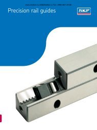
Standard rails www.lmotion.ru skf@lmotion.ru Тел. (495)-921-34-60Product overviewRails with protective caps made ofplasticsRails with cover strip and coverstrip retaining clamps made of aluminium- without end face threaded holes(not required)35
www.lmotion.ru skf@lmotion.ru Тел. (495)-921-34-60Accuracy classes, dimensions and designationsLLRHR railsFor mounting from above with plasticmounting caps (supplied).NoteThe rails can also be supplied inseveral parts.Type designation and rail lengthsStandard rail Rail Rail Pitchone-piece multi-piece TSize Accuracy Designation Designation [mm]15 P5 LLRHR 15 - xxxx P5 LLRHR 15 - xxxx P5 A 60P3 LLRHR 15 - xxxx P3 LLRHR 15 - xxxx P3 AP1 LLRHR 15 - xxxx P1 LLRHR 15 - xxxx P1 AP01 LLRHR 15 - xxxx P01 LLRHR 15 - xxxx P01 AP001 LLRHR 15 - xxxx P001 LLRHR 15 - xxxx P001 A20 P5 LLRHR 20 - xxxx P5 LLRHR 20 - xxxx P5 A 60P3 LLRHR 20 - xxxx P3 LLRHR 20 - xxxx P3 AP1 LLRHR 20 - xxxx P1 LLRHR 20 - xxxx P1 AP01 LLRHR 20 - xxxx P01 LLRHR 20 - xxxx P01 AP001 LLRHR 20 - xxxx P001 LLRHR 20 - xxxx P001 A25 P5 LLRHR 25 - xxxx P5 LLRHR 25 - xxxx P5 A 60P3 LLRHR 25 - xxxx P3 LLRHR 25 - xxxx P3 AP1 LLRHR 25 - xxxx P1 LLRHR 25 - xxxx P1 AP01 LLRHR 25 - xxxx P01 LLRHR 25 - xxxx P01 AP001 LLRHR 25 - xxxx P001 LLRHR 25 - xxxx P001 A30 P5 LLRHR 30 - xxxx P5 LLRHR 30 - xxxx P5 A 80P3 LLRHR 30 - xxxx P3 LLRHR 30 - xxxx P3 AP1 LLRHR 30 - xxxx P1 LLRHR 30 - xxxx P1 AP01 LLRHR 30 - xxxx P01 LLRHR 30 - xxxx P01 AP001 LLRHR 30 - xxxx P001 LLRHR 30 - xxxx P001 A35 P5 LLRHR 35 - xxxx P5 LLRHR 35 - xxxx P5 A 80P3 LLRHR 35 - xxxx P3 LLRHR 35 - xxxx P3 AP1 LLRHR 35 - xxxx P1 LLRHR 35 - xxxx P1 AP01 LLRHR 35 - xxxx P01 LLRHR 35 - xxxx P01 AP001 LLRHR 35 - xxxx P001 LLRHR 35 - xxxx P001 A45 P5 LLRHR 45 - xxxx P5 LLRHR 45 - xxxx P5 A 105P3 LLRHR 45 - xxxx P3 LLRHR 45 - xxxx P3 AP1 LLRHR 45 - xxxx P1 LLRHR 45 - xxxx P1 AP01 LLRHR 45 - xxxx P01 LLRHR 45 - xxxx P01 AP001 LLRHR 45 - xxxx P001 LLRHR 45 - xxxx P001 Abold text = standard rangexxxx = rail length36
www.lmotion.ru skf@lmotion.ru Тел. (495)-921-34-60Size Dimensions (mm) WeightW H 4±0,5H 7 d 2 d 3 E 1 min F L max kg/m15 15 16,20 10,3 7,4 4,4 10 60 4 000 1,420 20 20,55 13,2 9,4 6,0 10 60 4 000 2,425 23 24,25 15,2 11,0 7,0 10 60 4 000 3,230 28 28,35 17,0 15,0 9,0 12 80 4 000 5,035 34 31,85 20,5 15,0 9,0 12 80 4 000 6,845 45 39,85 23,5 20,0 14,0 16 105 4 000 10,5The “E” dimension designates thedistance from the rail end to thecentre of the first attachment hole.If no customer-specific “E” dimensionis provided with the order, therails are produced according to thefollowing formula:The distance of the first and lastattachment holes is mediated.If several possibilities arise, theshorter “E” dimension will be produced!L - (z -1) x FE =2E = Rail end dimensionF = Distance of attachment holesL = Rail lengthz = Number of attachment holes37
www.lmotion.ru skf@lmotion.ru Тел. (495)-921-34-60LLRHR D2 railsFor mounting from above with coverstrip and strip retaining clamps.• Robust cover strip retainingclamps made of aluminium• Rail without end face threadedholes (not required for coverstrip retaining clamps)NoteThe rails can also be supplied inseveral parts.Type designation and rail lengthsStandard rail Rail Rail Pitchone-piece multi-piece TSize Accuracy Designation Designation [mm]15 P5 D2 LLRHR 15 - xxxx P5 D2 LLRHR 15 - xxxx P5 A D2 60P3 D2 LLRHR 15 - xxxx P3 D2 LLRHR 15 - xxxx P3 A D2P1 D2 LLRHR 15 - xxxx P1 D2 LLRHR 15 - xxxx P1 A D2P01 D2 LLRHR 15 - xxxx P01 D2 LLRHR 15 - xxxx P01 A D2P001 D2 LLRHR 15 - xxxx P001 D2 LLRHR 15 - xxxx P001 A D220 P5 D2 LLRHR 20 - xxxx P5 D2 LLRHR 20 - xxxx P5 A D2 60P3 D2 LLRHR 20 - xxxx P3 D2 LLRHR 20 - xxxx P3 A D2P1 D2 LLRHR 20 - xxxx P1 D2 LLRHR 20 - xxxx P1 A D2P01 D2 LLRHR 20 - xxxx P01 D2 LLRHR 20 - xxxx P01 A D2P001 D2 LLRHR 20 - xxxx P001 D2 LLRHR 20 - xxxx P001 A D225 P5 D2 LLRHR 25 - xxxx P5 D2 LLRHR 25 - xxxx P5 A D2 60P3 D2 LLRHR 25 - xxxx P3 D2 LLRHR 25 - xxxx P3 A D2P1 D2 LLRHR 25 - xxxx P1 D2 LLRHR 25 - xxxx P1 A D2P01 D2 LLRHR 25 - xxxx P01 D2 LLRHR 25 - xxxx P01 A D2P001 LLRHR 25 - xxxx P001 D2 LLRHR 25 - xxxx P001 A D230 P5 D2 LLRHR 30 - xxxx P5 D2 LLRHR 30 - xxxx P5 A D2 80P3 D2 LLRHR 30 - xxxx P3 D2 LLRHR 30 - xxxx P3 A D2P1 D2 LLRHR 30 - xxxx P1 D2 LLRHR 30 - xxxx P1 A D2P01 D2 LLRHR 30 - xxxx P01 D2 LLRHR 30 - xxxx P01 A D2P001 D2 LLRHR 30 - xxxx P001 D2 LLRHR 30 - xxxx P001 A D235 P5 D2 LLRHR 35 - xxxx P5 D2 LLRHR 35 - xxxx P5 A D2 80P3 D2 LLRHR 35 - xxxx P3 D2 LLRHR 35 - xxxx P3 A D2P1 D2 LLRHR 35 - xxxx P1 D2 LLRHR 35 - xxxx P1 A D2P01 D2 LLRHR 35 - xxxx P01 D2 LLRHR 35 - xxxx P01 A D2P001 D2 LLRHR 35 - xxxx P001 D2 LLRHR 35 - xxxx P001 A D245 P5 D2 LLRHR 45 - xxxx P5 D2 LLRHR 45 - xxxx P5 A D2 105P3 D2 LLRHR 45 - xxxx P3 D2 LLRHR 45 - xxxx P3 A D2P1 D2 LLRHR 45 - xxxx P1 D2 LLRHR 45 - xxxx P1 A D2P01 D2 LLRHR 45 - xxxx P01 D2 LLRHR 45 - xxxx P01 A D2P001 D2 LLRHR 45 - xxxx P001 D2 LLRHR 45 - xxxx P001 A D2bold text = standard rangexxxx = rail length38
www.lmotion.ru skf@lmotion.ru Тел. (495)-921-34-60Size Dimensions (mm) WeightW H 4 H 7 H 6 L 8 L 7 d 2 d 3 E 1 min F L max kg/m15 15 16,3 10,3 7,3 12,0 2,0 7,4 4,4 10 60 3 000 1,420 20 20,75 13,2 7,1 12,0 2,0 9,4 6,0 10 60 4 000 2,425 23 24,45 15,2 8,2 13,0 2,0 11,0 7,0 10 60 4 000 3,230 28 28,5 17,0 8,7 13,0 2,0 15,0 9,0 12 80 4 000 5,035 34 32,15 20,5 11,7 16,0 2,2 15,0 9,0 12 80 4 000 6,845 45 40,15 23,5 12,5 18,0 2,2 20,0 14,0 16 105 4 000 10,5The “E” dimension designates thedistance from the rail end to thecentre of the first attachment hole.If no customer-specific “E” dimensionis provided with the order, therails are produced according to thefollowing formula:The distance of the first and lastattachment holes is mediated.If several possibilities arise, theshorter “E” dimension will be produced!E =L - (z -1) x F2E = Rail end dimensionF = Distance of attachment holesL = Rail lengthz = Number of attachment holes39
Ordering key www.lmotion.ru skf@lmotion.ru Тел. (495)-921-34-60LLR HTypeBellows (for bellows only)*BCarriage (carriage only)*CRail (rail only)*RSystem (carriage and rail)**SAccessories, if ordered separately*ZCarriage size (write relevant number)15, 20, 25, 30, 35, 45 XXCarriage typeFlange short, standard heightSAFlange normal, standard heightAFlange long, standard heightLASlim line short, standard heightSUSlim line normal, standard heightUSlim line long, standard heightLUSlim line normal, highRSlim line long, highLRCarriage with ball retainer (If not selected - no code)YesBNumber of carriages per rail1, 2, 4, 6, ... XPreload classPlayT0Light preload, 0,02 x CT1Medium preload, 0,08 x CT2Heavy preload, 0,13 x CT3Rail length80 mm - 4 000 mm (step in 1 mm) XXXXPrecision classStandardP5MediumP3HighP1SuperP01UltraP001No. of parallel mounted rail tracks in customized application (If not selected - no code)2, 3, .... (write relevant number for "x") WxJointed rail track (If not selected - no code)YesABellows (If not selected - no code)System complete with bellowsBKit, type 2 (carriage thru the end of the rail)*B2Kit, type 4 (between two carriages)*B4Cover stripOrdered separately*CSGuard type 2 (aluminium)*CSGRailRail, if customized according to drawing numberDRail, with cover strip and cover strip guard type 2 (aluminium)D2Distance between end face and first hole of the rail"E" dimension to be calculated - see page 37 or 39EIf no "E" specified the holes will be symmetric 0Coating (If not selected - no code)Duralloy, coated system (balls and tracks are not coated)System, (carriage mounted on rail, acc. not mounted) (If not selected - no code)YesLubrication adapter, option for high carriages (If not selected - no code)YesSealingScraper plateTwo piece front sealSeal kit, two piece front seal with scraper plateArbour for creating a sliding fit for the cover strip (If not selected - no code)Yes* When ordered separately (not in a system).** System consisting of carriage and railAn key with all positions in fat blue fonts qualifies the product for the easy range concept (quick delivery).HDMOS1S2S3W40
Notes www.lmotion.ru skf@lmotion.ru Тел. (495)-921-34-6041
42www.lmotion.ru skf@lmotion.ru Тел. (495)-921-34-60
Accessorieswww.lmotion.ru skf@lmotion.ru Тел. (495)-921-34-60Product overviewScraper plateTwo-piece front sealSealing kitBellowsLubrication adapterExpanding mandrelLoose cover stripCover strip retaining clampsmade of aluminium43
www.lmotion.ru skf@lmotion.ru Тел. (495)-921-34-60Standard carriagesScraper plate• Material: stainless spring steelto DIN EN 10088• Condition: bright• Precision design with 0,2 to0,3 mm maximum gapmeasurementMounting:Fastening screws are supplied.During mounting please ensure aneven gap between the rail andscraper plate.Scraper plate for rails with andwithout cover stripANote:Use in combination with two-piecefront seal kit LLRHZxxS3.H 245°S 2 S 3W 3E 9DA 1Size Part numbers Dimensions (mm) Weight (g)A A 1 H 2 W 3 E 9 S 2 S 3 D15 LLRHZ 15 S1 33 26,4 19,2 24,55 6,3 4,6 3,5 1,0 420 LLRHZ 20 S1 42 40,0 24,8 32,4 6,8 5,1 4 1,0 625 LLRHZ 25 S1 47 41,6 29,5 38,3 11,0 7 4 1,0 830 LLRHZ 30 S1 59 52,8 34,7 48,4 14,1 7 4 1,0 1235 LLRHZ 35 S1 69 60,9 40,1 58,0 17,0 7 4 1,0 1635* LLRHZ 35 S1 CS 69 60,9 40,1 58,0 17,0 7 4 1,0 1645 LLRHZ 45 S1 85 76,7 50,0 69,8 20,5 7 5 2,0 5045* LLRHZ 45 S1 CS 85 76,7 50,0 69,8 20,5 7 5 2,0 50* Scraper plates in combination with cover strip44
www.lmotion.ru skf@lmotion.ru Тел. (495)-921-34-60Two-piece front sealAW 3S 3 D 2S 2H 2E 945A 1D 1Size Part numbers Dimensions (mm) Weight (g)A A 1 H 2 W 3 E 9 S 2 S 3 D 1 D 215 LLRHZ 15 S2 32 27 19,0 24,55 6,3 3,5 3,5 3,0 2,2 620 LLRHZ 20 S2 42 39 24,3 32,4 6,8 5,1 4 3,3 2,5 825 LLRHZ 25 S2 47 42 29,0 38,3 11,0 7 4 3,3 2,5 1030 LLRHZ 30 S2 59 53 34,5 48,4 14,1 7 4 4,5 3,3 1835 LLRHZ 35 S2 69 61 39,5 58,0 17,0 7 4 4,5 3,3 2545 LLRHZ 45 S2 85 77 49,5 69,8 20,5 7 5 5,5 4,0 55Seal kitThe seal kit consists of the followingcomponents:1 Scraper plate2 Support plate3 Two-piece front seal123SizeSeal kitDesignation15 LLRHZ 15 S320 LLRHZ 20 S325 LLRHZ 25 S330 LLRHZ 30 S335 LLRHZ 35 S335 CS* LLRHZ 35 S3 CS45 LLRHZ 45 S345 CS* LLRHZ 45 S3 CS*Seal kit in combination with cover strip45
www.lmotion.ru skf@lmotion.ru Тел. (495)-921-34-60Lubrication adapterFor high carriages:LLRHC_RLLRHC_LR• Material: plastic• Contents: 1 pieceMounting:O-rings are supplied.D 1F 1FF 2F 3DType designations anddimensionsSize Part numbers Dimensions (mm)D D 1 D 2 F F 1 F 2 F 315 LLRHZ 15 0 12 6,2 3,4 3,70 3,10 0,50 3,2025 LLRHZ 25 0 15 7,2 4,4 3,80 3,20 0,50 5,8530 LLRHZ 30 0 16 7,2 4,4 2,80 2,20 0,50 6,1035 LLRHZ 35 0 18 7,2 4,4 6,80 6,20 0,50 6,8045 LLRHZ 45 0 20 7,2 4,4 9,80 9,20 0,50 8,3046
www.lmotion.ru skf@lmotion.ru Тел. (495)-921-34-60Mounting of lubrication adapterA lubrication adapter is necessary onhigh carriages if lubrication is to takeplace from the table part.In the recess for the O-ringseal a further small recess (1) hasbeen preformed. Do not drill thisopen. Risk of dirt incursion!• Heat up metal tip (2) with adiameter of 0,8 mm.• Carefully open the recess (1)with the metal tip and pushthrough.Observe maximum permissibledepth T max stated in thetable!• Insert O-ring seal (3) in therecess.• Insert lubrication adapter at anangle in the recess and pressthe flattened side (4) onto thesteel part (5). Use grease forfixing.ø 0,846351T max20,5• Insert O-ring seal (6) in thelubrication adapter.SizeTop lubrication opening: maximumpermissible depth for penetrationT max (mm)Lubrication nipple dimensionsSizeTop lubrication opening:maximum permissible depthfor penetration T max (mm)15 3,620 3,925 3,330 6,635 7,545 8,81,65M38M6DIN 3405, funnel-type nipplefor carriage size 15 and 20DIN 71412, cone-type nipplefor carriage size 25, 30, 35 and 4547
www.lmotion.ru skf@lmotion.ru Тел. (495)-921-34-60BellowsMaterial:Bellows are made out of polyesterfabric with polyurethane coatingAdapter plates are made out ofaluminium.The lubrication nipple on thecarriage can be used.Size Type 2with fastening plate for thecarriage and end plate for the railType 4with two fastening platesfor the carriagesType 9loose bellows (spare part)15 LLRHB 15 B2 xx LLRHB 15 B4 xx LLRHB 15 xx20 LLRHB 20 B2 xx LLRHB 20 B4 xx LLRHB 20 xx25 LLRHB 25 B2 xx LLRHB 25 B4 xx LLRHB 25 xx30 LLRHB 30 B2 xx LLRHB 30 B4 xx LLRHB 30 xx35 LLRHB 35 B2 xx LLRHB 35 B4 xx LLRHB 35 xx45 LLRHB 45 B2 xx LLRHB 45 B4 xx LLRHB 45 xxxx = Number of folds48
www.lmotion.ru skf@lmotion.ru Тел. (495)-921-34-60MountingThe bellows are pre-mounted.The fixing screws are supplied.On type 2 in each case one threadM4-10 deep, 2 x 45º countersunk,must be inserted in the end face ofthe rail.S 9 S 9A 412L max.L min.N 8H H 3 H 4N 72Size 25 - 45:The lubrication nipple on the carriagecan be used.S 7a)WH 3 H 4Size 15 and 20:A drive-type lubrication nipple issupplied.Calculation of the bellowsCalculation of the rail lengthL min = L max - StrokeL min. L A L max.L max = (Stroke + 30) · ULNumber of folds = maxW+ 2L A= Carriage length L 1 plus2x12 mm for the fasteningplates.L max = Bellows stretchedL min = Bellows pushedtogetherStroke = Stroke (mm)U = Calculation factorW = Maximum extensionof foldsL= L min + L max + L A L = Rail length (mm)LDimensions of the bellowsSize Dimensions (mm) FactorA 4 B 3 H H 3 H 4 N 7 N 8 S 7 S 8 S 9 W U15 45 11 24 26,5 31,5 11 3,4 M4 ø3 M3 19,9 1,1820 42 12 30 24,0 29,2 13 3,5 M4 ø3 M3 10,3 1,3325 45 12 36 28,5 35,0 15 6,0 M4 M6 M3 12,9 1,3230 55 12 42 34,0 41,0 18 8,0 M4 M6 M6 15,4 1,2535 64 12 48 39,0 47,0 22 8,0 M4 M6 M6 19,9 1,1845 83 12 60 49,0 59,0 30 8,0 M4 M6 M6 26,9 1,1349
www.lmotion.ru skf@lmotion.ru Тел. (495)-921-34-60Cover stripAdvantages of the cover stripThe cover strip can be simplyclipped on and pulled off.• This considerably simplifiesand quickens mounting:- It is not necessary to closeevery single drill hole- It is not necessary to waitfor the adhesive to set onadhesive strips.• Multiple mounting andremoval is possible(up to 4 times)Designs/FunctionsCover strip with fixed seat(standard)• The cover strip is clipped onbefore the carriages aremounted and stays firmly inplace.With an optionally available expandingmandrel for 0,15 mm coverstrips or a special expanding tool for0,3 mm cover strips a slide can alsobe retroactively created in order toremove a cover strip.In particular, however, the slidelength X can be optimally adapted tothe specific application.Please observe the precisemounting instructions!XX50
www.lmotion.ru skf@lmotion.ru Тел. (495)-921-34-60Cover strip for initial mounting/stock/replacementFor each guide rail length a matchingcover strip with fixed seat can besupplied.LOrdering a standard cover stripwith fixed seatExample:Rail Size 35,Rail length L = 2 696 mmLLRHZ 15 – 2 969 CS(For order designation seeproduct table)Size Standard cover stripsOrder designation, length (mm)15 LLRHZ 15 - xxx CS20 LLRHZ 20 - xxx CS25 LLRHZ 25 - xxx CS30 LLRHZ 30 - xxx CS35 LLRHZ 35 - xxx CS45 LLRHZ 45 - xxx CSExpanding mandrel to create a slideon the cover stripSize Expanding mandrelOrder designation15 LLRHZ 15 W20 LLRHZ 20 W25 LLRHZ 25 W30 LLRHZ 30 W35 LLRHZ 35 W45 LLRHZ 45 W51
52www.lmotion.ru skf@lmotion.ru Тел. (495)-921-34-60
www.lmotion.ru skf@lmotion.ru Тел. (495)-921-34-60Cover strip retaining clampsFor guide rails without end-facethreaded holes.<strong>SKF</strong> recommends the use of coverstrip retaining clamps.These can:• prevent unintentional removalof the strip and incursionof dirt• fix the cover strip in placeMaterials:Retaining clamps made of aluminium,black anodised.Clamping screw and nut made ofcorrosion-resistant steel.Order designations for cover stripretaining clampsSize Retaining clamps (2 pieces per unit) Dimensions (mm)Order designationH 6 L 7 L 815 LLR 15 CSG 7,3 2,0 1220 LLR 20 CSG 7,1 2,0 1225 LLR 25 CSG 8,2 2,0 1330 LLR 30 CSG 8,7 2,0 1335 LLR 35 CSG 11,7 2,2 1645 LLR 45 CSG 12,5 2,2 18Plastic caps are supplied as standardif a cover strip has not beenordered.53
Mounting instructions www.lmotion.ru skf@lmotion.ru Тел. (495)-921-34-60General mounting instructionsGeneral instructionsThe following mounting instructionsapply to all profile rail guides.Please note, however, that differingspecifications exist concerningthe parallelism of the rails as well asthe screwing and pinning of the carriages.These are therefore assignedto the individual versions.Ball profile rail guides. are highqualityproducts. Greatest possiblecare should be taken during transportand subsequent assembly. Allsteel parts have been oil-protected.The protection materials do notneed to be removed if the recommendedlubricants are used.Assembly examplesRails:Each rail has ground referenceedges on both sides.Options for lateral fixing:1 Stop edges2 Clamp strips3 Wedge stripsNoteThe rail must have a chamfer toprevent the seal from being damaged.This is not the case for jointrail tracksRails without lateral fixing must bealigned straight and parallel duringassembly, preferably using an auxiliarystrip.(Guide values for the permissiblelateral force without additional lateralfixing can be obtained from theinformation for the individual versions).Detailed mounting instructions areavailable through your normal <strong>SKF</strong>contact.412Carriage:Each carriage has a ground referenceedge on one side (dimensionH3 in the dimensional drawings).Additional fixing options:1 Reference edges2 Retaining strips3 Clamp strips4 PinningNoteAfter being successfully mounted thecarriage should move easily whenpushed.1354
www.lmotion.ru skf@lmotion.ru Тел. (495)-921-34-60Stop edges, corner radii, screwsizes and tightening torquesCarriages made of steel,type A, LA• Standard widthrO 4 O 42h 2N 8r 2O 2 O 1h 2r 2O 5N 8Rails• Can be screwed from aboveh 1r 1h 2O 3h 1r 1r 1h 1O 6O 3Carriages made of steel, type U,LU, R, LRRails• Can be screwed from aboveThe combinations shown are examples. In principle all carriages can becombined with all rails.h 1 r 1 h 2 r 2 O 1 O 22)O 41)2)O 5 O 3 O 6 N 8Size min. max. max. max. DIN 912 DIN 6912 DIN 912 DIN 912 DIN 912 DIN 912(mm) (mm) (mm) (mm) (mm) 4 Pieces 2 Pieces 6 Pieces 4 Pieces (mm)15 2,5 3,5 0,4 4 0,6 M4x12 M4x10 M5x12 M4x12 M4x20 M5x12 620 2,5 4,0 0,6 5 0,6 M5x16 M5x12 M6x16 M5x16 M5x25 M6x16 925 3,0 5,0 0,8 5 0,8 M6x20 M6x16 M8x20 M6x18 M6x30 M6x20 1030 3,0 5,0 0,8 6 0,8 M8x25 M8x16 M10x20 M8x20 M8x30 M8x20 1035 3,5 6,0 0,8 6 0,8 M8x25 M8x20 M10x25 M8x25 M8x35 M8x25 1345 4,5 8,0 0,8 8 0,8 M10x30 M10x25 M12x30 M10x30 M12x45 M12x30 14Dimensions and guide values forpermissible lateral force withoutadditional lateral fixingScrew strength Carriages RailsclassCarriages A, U, R 8.8 0,11 C 0,15 C 3) 0,23 C 0,11 C 0,06 C 0,06 C12.9 0,18 C 0,22 C 3) 0,35 C 0,18 C 0,10 C 0,10 CCarriages LA, LU, LR 8.8 0,08 C 0,13 C 3) 0,18 C 0,08 C 0,04 C 0,04 C12.9 0,14 C 0,18 C 3) 0,26 C 0,14 C 0,07 C 0,07 C1) If the carriage is fastened from above with only four O 4 screws:• permissible lateral force 1/3 lower• lower stiffness2) If the carriage is fastened with 6 screws:Tighten the middle screws with a tightening torque for strength class 8.83) If fastened with two O 2 screws and four O 1 screwsTightening torques of thefixing screws in NmM4 M5 M6 M8 M10 M12 M14 M168.8 2,7 5,5 9,5 23 46 80 125 19512.9 4,6 9,5 16 39 77 135 215 34055
www.lmotion.ru skf@lmotion.ru Тел. (495)-921-34-60PinningIf the guide values for the permissiblelateral force are exceeded (seetable) the carriage must be additionallyfixed by means of pinning orstop edges.The recommended dimensions forthe pin holes can be obtained fromthe drawings and table.S 10L 10W 4Usable pins:• tapered pin (hardened) or• straight pin DIN ISO 8734InstructionsFor production-related reasons theremay be pilot drill holes in the middleof the carriage at the recommendedpositions for pin holes († < S 10 ).They are suitable for drilling.If necessary, the pinning must becarried out in a different position(e.g. middle lube port), but must notexceed the dimension L 3 in longitudinaldirection (L 3 can be obtainedfrom the dimension tables for theindividual versions).Keep to dimensions W 2 and W 4 !Do not complete the pin holesuntil after mounting (see also generalmounting instructions - availablethrough your normal <strong>SKF</strong> contact).Standard width A, LAS 10N 9W 2Slim line U, LUSlim line high R, LRSizeDimensions (mm)Tapered pin (hardened) orstraight pin (DIN 6325)S 10 L 10 W 2 W 4 N 9 (max)15 4 18 26 38 6,020 5 24 32 53 7,525 6 32 35 55 9,030 8 36 40 70 12,035 8 40 50 80 13,045 10 50 60 98 18,056
www.lmotion.ru skf@lmotion.ru Тел. (495)-921-34-60Stop edges, corner radii, screwsizes and tightening torquesCarriages SA• Standard width, shortOr 1 O 2 r 4 2N 8h 2h 2O 3 O6Rails• Can be screwed from aboveh 1 h 1r 1r 1Carriages SU• Slim line shortRails• Can be screwed from aboveh 2r 2O 5N 8r 1h 1O 3NoteThe combinations shown are examples. In principle all carriages can becombined with all rails.The screw connection for the carriages using 2 screws is completelyadequate to withstand the maximum load. (See maximum load ability andmoment loadability for the individual versions.)Dimensions and guide values for permissible lateral force without additional lateral fixingSize h 1 r 1 h 2 r 2 O 1 O 4 O 5 O 3 O 6 N 8min. max. max. max. DIN 912 DIN 912 DIN 912 DIN 912 DIN 912(mm) (mm) (mm) (mm) (mm) 2 Pieces 2 Pieces 2 Pieces (Rail) (Rail) (mm)15 2,5 3,5 0,4 4 0,6 M4x12 M5x12 M4x12 M4x20 M5x12 620 2,5 4,0 0,6 5 0,6 M5x16 M6x16 M5x16 M5x25 M6x16 925 3,0 5,0 0,8 5 0,8 M6x20 M8x20 M6x18 M6x30 M6x20 1030 3,0 5,0 0,8 6 0,8 M8x25 M10x20 M8x20 M8x30 M8x20 1035 3,5 6,0 0,8 6 0,8 M8x25 M10x25 M8x25 M8x35 M8x25 13Screw strength class Carriages Rails8.8 0,08 C 0,12 C 0,08 C 0,09 C 0,09 C12.9 0,13 C 0,21 C 0,13 C 0,15 C 0,15 CTightening torques of the fixing screws in NmM4 M5 M6 M8 M10 M12 M14 M168.8 2,7 5,5 9,5 23 46 80 125 19512.9 4,6 9,5 16 39 77 135 215 34057
www.lmotion.ru skf@lmotion.ru Тел. (495)-921-34-60PinningIf the guide values for the permissiblelateral force are exceeded (seetable) the carriage must be additionallyfixed by means of pinning orstop edges.The recommended dimensions forthe pin holes can be obtained fromthe drawings and table.S 10L 10E 10Usable pins:• tapered pin (hardened) or• straight pin DIN ISO 8734InstructionsFor production-related reasons theremay be pilot drill holes in the middleof the carriage at the recommendedpositions for pin holes († < S 10 ).They are suitable for drilling.Flange short, SAW 4S 10N 9E 10W 2Slim line, SUSize Dimensions (mm)S 10 L 10 W 4 W 2 E 10 N 9 (max)15 4 18 38 26 9 3,020 5 24 53 32 10 3,525 6 32 55 35 11 7,030 8 36 70 40 14 10,035 8 40 80 50 15 12,0Tapered pin (hardened), straight pin (DIN 6325)58
www.lmotion.ru skf@lmotion.ru Тел. (495)-921-34-60Loading of the screw connectionsbetween rail and substructureThe screw connections specified inthe DIN 645-1 standard canbecome excessively loaded owing tothe high performance capacity of theprofile rail guides.M tmaxF maxThe screw connection between theguide rail and the substructure iscritical. If the lift-off loads (F) ormoments (M t ) are higher than therespective load values in the table,the screw connection must be recalculatedseparately.The figures apply to the followingconditions:• Grade 12.9 fixings screws• Screws tightened using atorque wrench• Slightly oiled screws(for grade 8.8 screwsapproximately a reductionfactor of 0,6 can be applied)Lift-off loads and momentRail screwed from aboveCarriageLLRH--SA,LLRH--SULLRH--A, LLRH--U,LLRH--RLLRH--LA, LLRH--LU,LLRH--LRF max. M t max. F max. M t max. F max. M t max.Size (N) (Nm) (N) (Nm) (N) (Nm)15 6 040 41 7 050 47 8 060 5420 10 000 90 11 700 106 13 400 12125 14 600 154 17 100 180 19 500 20530 - 360 32 400 420 37 100 48035 27 500 440 32 100 510 36 700 58045 - - 78 100 1 680 89 300 1 92059
www.lmotion.ru skf@lmotion.ru Тел. (495)-921-34-60Height deviationThe values for height deviation applyto all carriages.Approximately 20 % higher valuesare permissible for the SA(standard width short) and SU(slim line short) carriages.Given adherence to the permissibleheight deviation S 1 and S 2 , theinfluence on the service life is generallynegligible.Permissible height deviation inlongitudinal directionFor carriagesIn the permissible height deviationS 2 the tolerance “maximum differenceof dimension H on a rail”according to the table is alreadytaken into account in “TechnicalData”.Approximately 40 % higher valuesare permissible for SA and SU carriages.On A-type carriages (standardwidth long), LU and LR approx. 30 %lower values are permissible.S 1aS 2Permissible height deviation in lateraldirectionIn the permissible height deviationS 1 , the tolerance for dimension Haccording to the table is alreadytaken into account in “TechnicalData”.S 1 = a ¥ YS 1 = Permissible heightdeviation (mm)a = Distance between therails (mm)Y = Calculation factorPermissible height deviation S 2 oncarriagesS 2 = b ¥ 4,3 ¥ 10 -5S 2bY= Permissible heightdeviation (mm)= Distance between thecarriages (mm)= Calculation factorbCalculation factor Y for carriagesCalculation Preload classfactor T0 T1 T2 T3up to approx. 10 µm Preload Preload Preloadclearance 0,02 C 0,08 C 0,13 CY 4,3 ¥ 10 -4 2,8 ¥ 10 -4 1,7 ¥ 10 -4 1,2 ¥ 10 -460
www.lmotion.ru skf@lmotion.ru Тел. (495)-921-34-60Parallelism of mounted rails measuredon the rails and the carriagesThe values for the deviation in parallelismP 1 apply to allcarriages.Approximately 20 % higher valuesare permissible for the SA and SUcarriages.// = P1Deviation in parallelism P 1 forcarriagesThrough the deviation in parallelismP 1 the preload is increased somewhaton one side.If the table values are adhered to,the influence on the service life isgenerally negligible.The values shown in the followingtable apply to applications in whichhighest precision is required.For all other uses and for generalmechanical engineering doubled valuescan be applied.SizeDeviation in parallelism P1 (mm) for high precision demandsT0 T1 T2 T3up to approx. 10 µm Preload Preload Preloadclearance 0,02 C 0,08 C 0,13 C15 0,015 0,009 0,005 0,00420 0,018 0,011 0,006 0,00425 0,019 0,012 0,007 0,00530 0,021 0,014 0,009 0,00635 0,023 0,015 0,010 0,00745 0,028 0,019 0,012 0,00961
Maintenance www.lmotion.ru and lubricationskf@lmotion.ru Тел. (495)-921-34-60Maintenance and lubricationAs a function of the stroke lengthStroke > 2 ¥ length of the carriage• 1 lube port needs to beprovided per carriage.• Oil lubrication in accordancewith ISO VG 220.0 – max. 90°For lubrication quantities pleaserefer to the previous page.1 Lube port1 Lube portStroke < 2 ¥ length of the carriage• 2 lube ports need to beprovided per carriage.• Apply the prescribed lubricantquantity per lube port.• Oil lubrication in accordancewith ISO VG 220.2 Lube ports2 Lube ports0 – max. 90°For lubrication quantities pleaserefer to the next page.Installation in inclined or sideposition (wall mounting)Stroke > 2 ¥ length of the carriage• 1 lube port needs to beprovided per carriage.• Apply the lubricant quantitystated in the table with animpulse.• If the lubricant quantity cannotbe applied with an impulse,please consult <strong>SKF</strong>.1 Lube portFor 1 lube port0 – max. 90°0 – max. 90°2 Lube portsFor 2 lube ports62
www.lmotion.ru skf@lmotion.ru Тел. (495)-921-34-60MaintenanceDirt can drop and settle on exposedrails in particular. To maintain thefunction of seals and cover strips,such dirt must be regularly removed.For this purpose a “cleaning stroke”should be carried out over the entirelength of travel at least twice a day,and at the latest after eight hours.Carry out a cleaning stroke eachtime before switching off themachine.LubricationGrease lubricationInitial lubrication of the carriage(basic lubrication)No initial lubrication is required ifthe carriage has been greased at thefactory.The initial lubrication takes placewith three times the part quantitystated in Table 1:Observe the manufacturer’s instructions,in particular instructions concerningincompatibilities.Greases with a proportion of solidlubricant (such as graphite) shouldnot be used!Re-lubricating the carriageWhen the re-lubrication intervalaccording to Table 2 has beenreached, the carriage must be lubricatedwith the lubricant quantity asstated in Table 1. Where such environmentalinfluences as dirt, the useof coolants, vibration, shock loadsetc. are encountered, we recommendthat the re-lubrication intervalsbe shortened accordingly.Longer re-lubrication intervalsapply in the case of smaller loads.Short strokeStroke < 2 ¥ carriage length• 2 lube ports need to beprovided per carriage andlubricated in each case!Stroke < 0,5 ¥ carriage length• 2 lube ports need to beprovided per carriage andlubricated in each case!• For each lubrication cyclemove the carriage 2 ¥ thecarriage length. If this is notpossible, please consult <strong>SKF</strong>.Lubricant quantities as stated inTable 1 (re-lubrication). Apply thestated quantity for each lube port.* NLGI 00 greases reduce the relubricationintervals to 75 % of thevalues stated in Table 2.1. Grease the carriage with thefirst part quantity stated intable 1.2. Move the carriage backwardsand forwards with three doublestrokes along at least three timesthe carriage length.3. Repeat step 1 and 2 twice.4. Check whether a lubricatingfilm is visible on the rail.Ball rail guides are supplied in protectedform. With basic greasing atthe factory, both grease and oillubrication is possible.For lubrication we recommendlubricating grease to DIN 51825: –KP2K-20, consistency class NLGI 2to DIN 51818. This can be obtainedfrom <strong>SKF</strong>, see recommendation forlubricating greases.Never start to use carriages withoutbasic lubrication.Table 1Size Grease lubricationInitial lubrication by customer Part quantity (cm 3 ) Re-lubrication Part quantity (cm 3 )15 0,4 (x 3) 0,4 (x 2)20 0,7 (x 3) 0,7 (x 2)25 1,4 (x 3) 1,4 (x 2)30 2,2 (x 3) 2,2 (x 2)35 2,2 (x 3) 2,2 (x 2)45 4,7 (x 3) 4,7 (x 2)Table 2Size Grease lubricationRelubrication intervals under normal operating conditions, v ≤ 1 m/sTravel (km)under load ≤ 0,15 C ≤ 0,3 C15 5 000 1 20020 5 000 1 20025 10 000 2 40030 10 000 2 40035 10 000 2 40063
www.lmotion.ru skf@lmotion.ru Тел. (495)-921-34-60Oil lubricationOil quantities for initial lubricationand re-lubricationApply the entire quantity of oilwith a single lubrication impulse!Carriages initially greased at the factorycan also be re-lubricated withoil.If environmental influences suchas dirt, use of coolants, vibration,shock loads etc. are encountered, werecommend that the re-lubricationintervals be shortened accordingly.In the case of carriages whichhave not been initially greased at thefactory, carry out the initial lubricationin accordance with Table 3.Central oil lubricationOil quantities and lubricationimpulses for central oil lubricationNote:Recommended waiting timebetween the impulses:10 seconds.If environmental influences such asdirt, use of coolants, vibration, shockloads etc. are encountered, we recommendthat the re-lubricationintervals be shortened accordingly.Refer to Table 4.Table 3In the case of carriages which havenot been initially greased at the factory,carry out the initial lubricationin accordance with Table 3.SizeOil lubricationInitial lubrication by customerRe-lubricationPart quantity (cm 3 ) Part quantity (cm 3 )15 0,4 (x 2) 0,420 0,7 (x 2) 0,725 1,0 (x 2) 1,030 1,1 (x 2) 1,135 1,2 (x 2) 1,245 2,2 (x 2) 2,2Table 4SizeOil lubricationRe-lubrication intervals under normal operating conditions, v ≤ 1 m/sTravel (km)under load ≤ 0,15 C ≤ 0,3 C15 2 500 60020 2 500 60025 5 000 1 20030 5 000 1 20035 5 000 1 200For example size 45:4 impulses with in each case 0,6cm 3 in 30 seconds.Refer to Table 5.Table 5SizeCentral oil lubricationOil quantitiesImpulse (cm 3 )15 0,6 120 0,6 125 0,6 230 0,6 235 0,6 245 0,6 4Impulses per lubrication cycleNumber of impulses64
Notes www.lmotion.ru skf@lmotion.ru Тел. (495)-921-34-6065
Notes www.lmotion.ru skf@lmotion.ru Тел. (495)-921-34-6066
www.lmotion.ru skf@lmotion.ru Тел. (495)-921-34-6067
www.lmotion.ru skf@lmotion.ru Тел. (495)-921-34-60Linear guidingsContactsLinear motion from <strong>SKF</strong>www.linearmotion.skf.comBenelux<strong>SKF</strong> Multitec Benelux B.V.NederlandTel +31 030 6029 029Fax +31 030 6029 028België & LuxembourgTel +32 25 024 270Fax +32 25 027 336E-mail multitec_benelux@skf.comBrasil<strong>SKF</strong> do Brasil LtdaTel +55 11 461 991 114Fax +55 11 461 991 99E-mail marketing.skf@skf.com.brCanada<strong>SKF</strong> Canada LimitedTel +1 416 299 1220Fax +1 416 299 6548E-mail www.marketing@skf.caDanmark<strong>SKF</strong> MultitecTel +45 65 92 77 77Fax +45 65 92 74 77E-mail customerservice.multitec@skf.comDeutschland & Österreich<strong>SKF</strong> Linearsysteme GmbHTel +49 9721 657 232/233Fax +49 9721 657 111E-mail lin.sales@skf.comEspaña & Portugal<strong>SKF</strong> Productos Industriales S.A.Tel +34 93 377 99 07/-77Fax +34 93 474 2039/-2156E-mail prod.ind@skf.comFrance<strong>SKF</strong> EquipementsTel +33 1 30 12 73 00Fax +33 1 30 12 69 09E-mail equipements.france@skf.comItalia<strong>SKF</strong> Multitec S.p.A.Tel +39 011 22 49 01Fax +39 011 22 49 233E-mail multitec.italy@skf.comMexico<strong>SKF</strong> de México S.A. de C.VTel +52 222 229 4900Fax +52 222 229 4908Web www.skf.com.mxNorge<strong>SKF</strong> MultitecTel +47 22 90 50 00Fax +47 22 30 28 14E-mail customerservice.multitec@skf.comSchweiz<strong>SKF</strong> LM&PTTel +41 44 825 81 81Fax +41 44 825 82 82E-mail skf.schweiz@skf.comSuomi<strong>SKF</strong> MultitecTel +358 9 615 00 850Fax +358 9 615 00 851E-mail multitec.nordic@skf.comSverige<strong>SKF</strong> MultitecTel +46 42 253 500Fax +46 42 253 545E-mail customerservice.multitec@skf.comU.K.<strong>SKF</strong> (UK) Ltd.Tel +44 1582 496 735Fax +44 1582 496 574E-mail a&mc.uk@skf.comUSA<strong>SKF</strong> Motion TechnologiesTel +1 610 861 4800Toll free +1 800 541 3624Fax +1 610 861 4811E-mail motiontech.usa@skf.comOther countriesFax +49 972 657 118E-mail guidings@skf.comRepresented by:<strong>SKF</strong> is a registered trademark of the <strong>SKF</strong> Group.© <strong>SKF</strong> 2006The contents of this publication are the copyright of the publisher and may not be reproduced (even extracts) unless prior written permission is granted.Every care has been taken to ensure the accuracy of the information contained in this publication but no liability can be accepted for any loss or damagewhether direct, indirect or consequential arising out of the use of the information contained herein.Publication <strong>6229EN</strong> - 0602APrinted in Sweden