VERTEC White Paper.indd - Jands
VERTEC White Paper.indd - Jands
VERTEC White Paper.indd - Jands

Create successful ePaper yourself
Turn your PDF publications into a flip-book with our unique Google optimized e-Paper software.
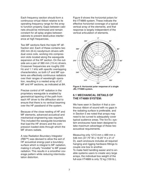
Each frequency section should form acontinuous virtual ribbon relative to itsoperating frequency range for the arrayto function properly. Gaps between cabinetsshould be minimized and remainconstant for all splay angles betweencabinets to prevent destructive interferenceat high frequencies.Two MF sections flank the triple HF diffractionslot. Each of these contains two200 mm (8-in) neodymium drivers withdual voice coils, working into compressionslots located along the waveguideexpansion of the HF section. On the outsideare a pair of 380 mm (15-in) drivers.Crossover frequencies are roughly 200Hz and 1.1 kHz with specific overlappingcharacteristics, so both LF and MF systemsare effectively continuous radiatorsover their ranges of wavelength operation,resulting in a nested array of LF,MF and HF sections, as indicated at 8A.Precise control of HF radiation in theproprietary waveguide is enabled bygeometrical tapering of the path fromeach HF driver to the diffraction slot toensure that there is no vertical beamingover the HF passband of the system.Because of the close nesting of HF andMF elements, advanced acoustical andmechanical engineering was required.This included the waveguide boundariesthat load the HF drivers and the compressionloaded slots through which theMF drivers radiate.A new Radiation Boundary Integrator(RBI) was devised to allow the exit ofHF acoustical energy past a boundarysurface which is integral to MF radiation,making it virtually “invisible” to MF powerradiation. This results in a smoother coveragepattern while reducing intermodulationdistortion.Figure 9 shows the horizontal polars forthe VT4889 system. These indicate theeffective horizontal coverage of a typicalvertical array of the elements, and thatresponse is largely independent of thevertical articulation of elements.Figure 9. Horizontal polar response of a singleJBL VT4889 system.6.1 MECHANICAL DETAILS OFTHE VT4889 SYSTEM:We have seen in Section 4 that a continuousribbon of sound with no gaps inthe radiating surface is preferable, andin Section 5 we noted that arrays mayneed to be curved to adequately covertypical audience areas. The <strong>VERTEC</strong> systemenclosures have been designed totake maximum advantage of these twoacoustical requirements.Measuring only 1213 mm x 489 mm x546 mm (47.75” W x 19.25” H x 21.4”D), each enclosure includes all requiredhanging and rigging hardware fittings tocouple one box to another.To make field handling easier and to enablesystems users to create very largearrays, the individual box weight of thefull-size VT4889 is only 72 kg (159 lb.),7