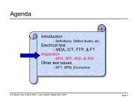
CJTAG - Board Test Workshop Home Page
CJTAG - Board Test Workshop Home Page
CJTAG - Board Test Workshop Home Page

Create successful ePaper yourself
Turn your PDF publications into a flip-book with our unique Google optimized e-Paper software.
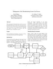
Problem: 1149.1 Data Volume required for test continues to grow=TemporarilyDownloadedAnd accessedvia 1149.1GigabitSerialBERTU3 FPGAFACSerialEEPROM1.8VDDRRAMFCRAMNot just high-volume products are a problem.Low BERT volume products with fast turn-around+Low volume products which require 1149.1ASICFPGADuring burn-in or ESSU2Mem U1Stand-alone +alone 1149.1 test when 1149.1 on ICTBIST isn’t t appropriate for cost and speed reasonsFAC LVDSFLASH<strong>Board</strong> <strong>Test</strong> Work Shop 2006
Early Commercial Addressable IC or ‘Gateways’- some attempts to solve the concurrent test problem- ‘apply only’ broadcast mode & LFSRTT = 10 sec TT = 10 sec TT = 10 secLSP1 LSP2 LSPNTotal <strong>Test</strong> Time= 30 sec1149.1ControllerTDOTCKTMSTDITRSTADDRScanBridge/ASPLFSRTRST* TDI TMS TCK TDOADDRScanBridge/ASPLFSRTRST* TDI TMS TCK TDOSB/ASP/look-alikes 1 don’t 2 have intelligence 3- they continue to program a FLASH or runan interconnect on the board regardless offailures encountered.<strong>Board</strong> <strong>Test</strong> Work Shop 2006ADDRScanBridge/ASPLFSRTRST* TDI TMS TCK TDO
Total <strong>Test</strong> Time = ~10 sec = 10secs plus failure extraction time (if any)TT = 10 secTT = 10 secTT = 10 secLSP1 LSP2 LSPNLSP1 LSP2 LSPNLSP1 LSP2 LSPN<strong>CJTAG</strong>ControllerTDOTCKTMSTDITRSTEXPMASKADDR1<strong>CJTAG</strong> IC<strong>CJTAG</strong> IC<strong>CJTAG</strong> ICCompareCircuitADDRCompareCircuitSupport for “Broadcast” mode – TDO = Z1149.1 control of Compare Circuit1149.1 (FAC) access 2 to ResultsN“Brake” to shut off paths on failures orAt end of test (SVF for instance) to preservediagnosticsParallel <strong>Test</strong> Bus<strong>Board</strong> <strong>Test</strong> Work Shop 2006ADDRCompareCircuit
. . .LSP0 LSP1 LSPNBrakeTDI Local Scan Path MatrixTDOMASKEXPEnableTRST* TMS TCKMDIEDIEnableCMPPath SelectFAILADISHIFTDR*SHIFTIR*LSPTLRTAD[7:0]SAD[7:0]ResultsUUT_TYPE_ADDRALIAS/GROUP_ADDR<strong>CJTAG</strong>_CFG/CMP CNTRLSLOT_ADDRPATH SELECTDevice IDBypassBOUNDARYTDOTDITRST*TMSTCKTAPControllerClockIRUpdateIRShiftIR*Reset*SelectTDOENShiftDR*UpdateDRClockDRInstruction RegisterSHIFTDR*SHIFTIR*<strong>CJTAG</strong>_ON*Enable<strong>Board</strong> <strong>Test</strong> Work Shop 2006
10In Multi-drop 1149.1, TDO is not active during Shift-DR, Shift-IRAnd Asynchronous TRST pin is unused during Shift-DR, Shift-IR<strong>Test</strong>-Logic-Reset011Run-<strong>Test</strong>/Idle Select-DR-Scan Select-IR-Scan001 1Capture-DRCapture-IR00Shift-DRShift-IR0111Exit1-DRExit1-IR00Pause-DRPause-IR0110 0Exit2-DRExit2-IR11Update-DRUpdate-IR1 01 01010<strong>Board</strong> <strong>Test</strong> <strong>Workshop</strong> 20069
Make <strong>CJTAG</strong> 5 1149.1 signal compatible• 5 Wire multi-drop 1149.1 bus -still compatible ASP & Scan Bridge•SB and <strong>CJTAG</strong> device have to have same IR length• TDO pin becomes Bidirectional (normally tri-state output)• Similar PCBs tested and configured In parallelIf the PCB test/programming time is 2 minutesThen six similar PCBs in the system would be 2 minutestest time, not 12 minutes as it would be with ASP orScanBridge• Scan Out data always compared locally, not sent back to controllerlerUnless … in single PCB mode.• Parallel Access, but individual access preserved– Program unique serial numbers<strong>Board</strong> <strong>Test</strong> <strong>Workshop</strong> 200610
Total <strong>Test</strong> Time = ~10 sec TDO becomes bidirectionalTT = 10 secTT = 10 secTT = 10 secLSP1 LSP2 LSPNLSP1 LSP2 LSPNLSP1 LSP2 LSPN<strong>CJTAG</strong> IC<strong>CJTAG</strong> IC<strong>CJTAG</strong> ICADDRCompareCircuitADDRCompareCircuitADDRCompareCircuit<strong>CJTAG</strong>Controller1TDO/EXPTCKTMSTDITRST/MASK2NParallel <strong>Test</strong> Bus<strong>Board</strong> <strong>Test</strong> Work Shop 2006
LSP0 LSP1 LSPNBrakeTDI Local Scan Path MatrixTDOMASKTRST*TAD[7:0]SAD[7:0]OREnableTRST* TMS TCKMDIEnableCMPResultsUUT_TYPE_ADDRALIAS/GROUP_ADDR<strong>CJTAG</strong>CFG/CMPCF/LINKSLOT_ADDRPATH SELECTDevice IDBypassBOUNDARYPath SelectFAILEDIADISHIFTDR*SHIFTIR*ATLTLRTDOEN1EXPTDOTDITMSTCKTRST*TAPControllerClockIRUpdateIRShiftIR*Reset*SelectTDOENShiftDR*UpdateDRClockDRInstruction Register<strong>CJTAG</strong>_ON*TDOEN1SHIFTDR*SHIFTIR*Enable<strong>Board</strong> <strong>Test</strong> Work Shop 2006
Multi-drop bus major disadvantage is that as PCBsAre added, each PCB is seen as a capacitive load.Each ‘address-able’ IC has ‘stub’(trace length from IC to Backplane connector )Connector capacitance, pitch etc. affect JTAG signalintegrity and max TCK frequencyBeyond 4-848 PCBs, TCK rates drop, affecting throughput andincreasing total test time- testing two UUTs at ½ max TCK is no betterthan one at the max TCK.Anecdotal evidence shows large systems with ASP/ScanBridge on 20+ PCBs have TCK rates < 10Mhz, sometimes
<strong>CJTAG</strong> approach enables Multi-Drop Segmentation•Higher TCK rates•re-synchronization of 1149.1 signals reduce skew•Minimize loads – as few as one load per driver•As you choose to implement•Extends and repeats <strong>CJTAG</strong> bus…as much asaddressing size will allow. 8bits = 255 UUTs,Address = N, then 2**N UUTsSynchronizer is controlled by <strong>CJTAG</strong> addressto determine when TDO must be enabled to sendData back to controller<strong>Board</strong> <strong>Test</strong> <strong>Workshop</strong> 200614
LSP0 LSP1 LSPNBrakeTDI Local Scan Path MatrixTDOMASKTRST*TAD[7:0]SAD[7:0]TDITMSTCKORTRST*EnableTAPControllerTRST* TMS TCKMDIEnableClockIRUpdateIRShiftIR*Reset*SelectTDOENShiftDR*UpdateDRClockDRCMPResultsUUT_TYPE_ADDRALIAS/GROUP_ADDR<strong>CJTAG</strong>CFG/CMPCF/LINKSLOT_ADDRPATH SELECTDevice IDBypassBOUNDARYInstruction RegisterFAILEDIADI<strong>CJTAG</strong>_ON*Path SelectSHIFTDR*SHIFTIR*TDO/EXPTDITMSTRST*/MASK_LINKTDO/EXPTCKATLTLRATL_LINKSYNCTDOEN1EXPTDOTDOEN1TDI_LINKTMS_LINKTRST*/MASK_LINKTDO/EXP_LINKTCK_LINKSHIFTDR*SHIFTIR*Enable<strong>Board</strong> <strong>Test</strong> Work Shop 2006
TDITMSTRST*/MASKSRC_REGD QD QD QLNK_REGD QD QD QTDI_LINKTMS_LINKTRST*/MASK_LINKTDO/EXPD QD QTDO/EXP_LINKQ DQ DEnableTCKEnableTCK_LINK<strong>Board</strong> <strong>Test</strong> Work Shop 2006
1 TCK delay fromPCB 1 & 21 TCK delay fromPCB 1 & 2ADDRPATH0PATH1TRST TDO TMS TCK TDI…PATHN<strong>CJTAG</strong> ICADDRPATH0PATH1…PATHN3 461 2 3 4ADDRAha! But now the scan-chain is broken if aTRST TDO TMS TCK TDI TRST TDO TMS TCK TDITRST TDO TMS TCK TDITRST TDO TMS TCK TDI TRST TDO TMS TCK TDIcard is missing!-Can be overcome with DFT – using ‘sync’ onSome added benefits:Fixed slots (known card is present)PCBs do not goSegmented through UPDATE-DR PTB at Bus in Backplanethe same time-In practice dummy cards are usedWe get concurrent test, without the major disadvantageSystems today:Of traditional concurrent test and that is in-rush currentpoint-to-point (SERDES) not Large passive parallel bplanerequirementsManyPCB are not physically far from the 1149.1 driver – in this casehave mechanical/Cooling requirements to have theno more than 1 slot awayslot populated with somethingAdvantages:PATH0<strong>CJTAG</strong> IC <strong>CJTAG</strong> IC <strong>CJTAG</strong> ICIn this design no more than two loads seen by 1149.1 driver(s)Easier to achieve propogation time of < 1/2TCK periodPATH1…PATHNADDRPATH0PATH1…PATHNN<strong>Board</strong> <strong>Test</strong> Work Shop 2006
1 TCK delay fromPCB 1 & 21 TCK delay fromPCB 1 & 2ADDRPATH0PATH1TRST TDO TMS TCK TDI…PATHN<strong>CJTAG</strong> ICADDRPATH0PATH1…PATHNTRST TDO TMS TCK TDI TRST TDO TMS TCK TDIADDRPATH0<strong>CJTAG</strong> IC <strong>CJTAG</strong> IC <strong>CJTAG</strong> ICPATH1…PATHNTRST TDO TMS TCK TDITRST TDO TMS TCK TDI TRST TDO TMS TCK TDIADDRPATH0PATH1…PATHN3 461 2 3 4NSegmented PTB Bus in BackplaneAdvantages:PCB are not physically far from the 1149.1 driver – in this caseno more than 1 slot awayIn this design no more than two loads seen by 1149.1 driver(s)Easier to achieve propogation time of < 1/2TCK period<strong>Board</strong> <strong>Test</strong> Work Shop 2006
ResultsSystemDescriptionPCBConfiguration(board types)TCKFreq.<strong>Test</strong>/ConfigTime perPCB1149.1<strong>Test</strong>Time<strong>CJTAG</strong><strong>Test</strong>Time<strong>Test</strong> TimeReductionEst. Costsavingsper testrunATelecomSystem2S + 8I20MhzS = 25s,I = 36s338s64s81%$4.56BTelecom PCB in‘mockup’ backplane16T5Mhz38secs152s*41s74%$1.80CcPCIsystem1S + 7I10MhzS=1,I=65s456s69s84%$6.45DFlashProgramming system16A10MhzW=105s,R=14 s476s*123s74%$5.83S = System <strong>Board</strong> I = I/O <strong>Board</strong> T=TelecomA= Automotive* Note: <strong>Test</strong> Time using 1149.1 controller with four independent scan-chains4 Port Controller could not perform diagnostics in‘concurrent’ mode. Some failures could not be repeated.On re-running the test.<strong>Board</strong> <strong>Test</strong> Work Shop 2006
<strong>CJTAG</strong> for concurrent test/programming on a single PCBDDRDDRDDRDDRDSPDDRDDRDDRDDRDDRDDRDDRDDRDDRDDRDDRDDRDSPDSPDSP<strong>CJTAG</strong>ControllerTDO/EXPTCKTMSTDITRST/MASK<strong>CJTAG</strong>ICDDRDDRDDRDDRDDRDDRDDRDDRDDRDDRDDRDDRDSPDDRDDRDDRDDRDSPDSPDSP<strong>Board</strong> <strong>Test</strong> Work Shop 2006
LSP0 LSP1 LSPNTDIATL0ATL1ATLNBrake[n:0]Local Scan Path MatrixTDOMASKTRST*ORATL_ADDR[n:0]EnableMDIEnableTRST* TMS TCK Path SelectCMPResults[n:1]FAIL[n:0]EDIADI[n:0]SHIFTDR*SHIFTIR*ATLATLTLRATL0TLRTLRSAD[7:0]ATL_ADDR[n:0]<strong>CJTAG</strong>CFG/CMPCFSLOT_ADDRPATH SELECTDevice IDBypassBOUNDARYTDOEN1EXPTDOTDITMSTCKTRST*TAPControllerClockIRUpdateIRShiftIR*Reset*SelectTDOENShiftDR*UpdateDRClockDRInstruction Register<strong>CJTAG</strong>_ON*TDOEN1SHIFTDR*SHIFTIR*Enable<strong>Board</strong> <strong>Test</strong> Work Shop 2006
1149.1Controller1149.1Controller1149.1ControllerFixed BandwidthSome controllersw/o diagnosticsShared Fixed Bandwidth of HostPTBScalable Bandwidthw/ Diagnostics1149.1 Controller<strong>CJTAG</strong>ControllerFixed Bandwidth of HostNth<strong>CJTAG</strong>ICFixture/<strong>Test</strong> Equipment Add-on<strong>Board</strong> <strong>Test</strong> Work Shop 2006
Broad architecture – not wires can implement inEthernet, PCI bus, USB, I2C or wireless as technology permitsLSP1 LSP2 LSPNLSP1 LSP2 LSPNLSP1 LSP2 LSPN<strong>CJTAG</strong> IC<strong>CJTAG</strong> IC<strong>CJTAG</strong> ICADDRWirelessTransceiverADDRWirelessTransceiverADDRWirelessTransceiver1EXP2 NMASKTMSTDITRST<strong>Board</strong> <strong>Test</strong> Work Shop 2006
Thank You!Thanks to my co-inventor Mike RicchettiThanks to Bill Eklow for the opportunity topresentThanks to Chen-HuanChiang for paper reviewNow for Questions<strong>Board</strong> <strong>Test</strong> Work Shop 2006