The Heathkit HR-20 - Nostalgic Kits Central
The Heathkit HR-20 - Nostalgic Kits Central
The Heathkit HR-20 - Nostalgic Kits Central

You also want an ePaper? Increase the reach of your titles
YUMPU automatically turns print PDFs into web optimized ePapers that Google loves.
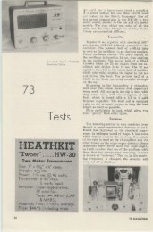
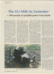
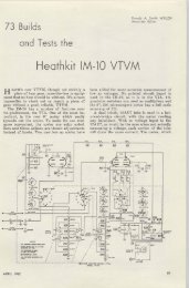
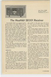
ceiver uses a scrlcs-purullel heater string, itwas necessary to change the 6U8 to a 12AX7and connect the nuvlstor ill parallel with the12AX7. Anoth er solution would b e to add asecond nuvistor as an rf amplifier.<strong>The</strong> results arc amuztng, as the limitercompletely eliminated all ignition noise frommy XK- J40, which was so noisy that I gave uptrying to operate 2 meter mobile from it. \Vithvery little effort, it should be possible to addthis limiter to an y receiver, and eliminate almostall qrn. . .. \VA 2I N~ 1Roy Pefe nberq W4WKMJ ohn Bowden W4SYJ73 Tests theHeath <strong>HR</strong>-<strong>20</strong> Mobile Receiver- ANOT II E H ~[OBILE RECEIVEH?W ell, 1I0 t exactly. W hile Heath calls their newIIH-<strong>20</strong> kit a mobile recei ver, an SSB receiverand, at times, a mobile SSB receiver, it ismore than this. <strong>The</strong> IIR-<strong>20</strong> is an advanceddesign amateur band receiver, less power supply,which provides, in a compact p ackage,those receiver characteristics and featureswhich Heath believed would provide the mostperformance for the money. As far as thewriters are concerned, Heath has a winner.<strong>The</strong> II R-<strong>20</strong> Receiver is a 7 tube (plus gasregulator, Zener diode and transistor regulator)single conversion superheterodyne receiverdesigned for C\\', SSB and A\ l receptionin the 80 through 10 meter amateurbands. Modern design techniques and componentsinsure excellent performance in allmodes. Before we go into the circuit details,a few comments regnrdiug the design philosophyand history of the lIH 30 Receiver arcin order.As shown in the photograph, the physicalconfiguration of the <strong>HR</strong>-<strong>20</strong> is similar to that36of the previous Heath mobile receive r, the~ lH-I Commanche. .Much of the circuitry, thepan el layout and physical dimen sions of th eorigina l model have been retained. <strong>The</strong> majorchanges are in new features for improved SSBreception. Included in these are replacementof the origina l variable frequen cy BFO witha d ual freq uency, crystal controlled oscillatorfor selectable sideband operation, selectableAC C time constant and a transistorized highfrequency oscilla tor filament voltage regulatorfor 12 volt de mobile operation.<strong>The</strong> initial design concept for the H H-<strong>20</strong>was as mobile receiver to be used in conjunctionwith the Heath HX-<strong>20</strong> Mob ile SSB T ransmitter.W hen used in this application, bothuni ts rnav be mounted on an accessorv basewhich is' available as the AK-6 ~I o b i l ~ BaseMount, Such an installation is shown in thesecond photograph. An external, 8 ohmspeaker is req uired and the AK-7 .\IobileSpeaker is available for this purpose. Heathalso markets the IIP-IO, 1:) volt dc powersupply for mobile use. This transistorized , 1<strong>20</strong>73 MAGAZINE
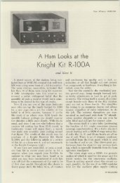
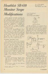
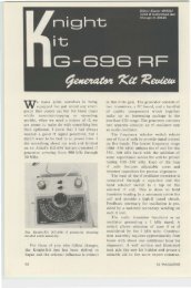
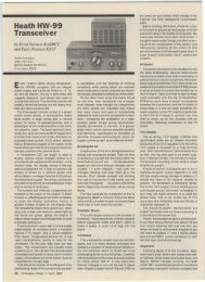
•~'r71.. --- -- -..,~, ,,, ...,---- _. ~-- -- - - - - - -,I 0;;- r-r- III,- -,,"..'"....... I~' -,I . ~ I...,i, ., ".. •• , • W ",- I... ... .. ... ---•• ~....•T~ : ....- I.....,..J ..-,I,.~1 ,.} -l'-, '-> •• l- I'- - - - - ---- -J...... ...- ..,......~-- ....~-~-" -__ _ I ..,.watt unit supplies power for both the llH-<strong>20</strong>Receiver and the IIX-<strong>20</strong> Transmitter in thenormal mohile installation.Both the IIH-<strong>20</strong> Receiver and the HX-<strong>20</strong>Transmitter are well suited for home stationuse and, in this application, Heath recommendsthei r II \V·<strong>20</strong> Utility ac Power Supply.Although th e H H-<strong>20</strong> is designed for easy integrationinto the home station or mobile installation,it may of course be used as ast raight, ham band receiver. In this case, allth at is required is an antenna, speaker anda power sup pIy considerably less elaboratethan those mentioned above. Power supply requirementsfor the receiver alone are shownin the specification chart.<strong>The</strong> lIH-<strong>20</strong> circuit diagram is a bit largeto include in areview article, however theblock diagram shown in F ig. 1 will aid inun derstanding th e following discussion. <strong>The</strong>receiver is a single conversion superhet usinga 3.0 rnc it with a crys tal lattice fi lter. A6RZ6 rf stage feeds a 6EA8 mixer-oscillatorstage which in tum feeds the crystal lattice itfilter. Use of the relatively high, 3.0 me iffre q uency, along with the selectivity p rovid edby the high Q rf and mixer grid circui ts, givesgood image rejection. <strong>The</strong> crystal lattice filterprovides the if bandpass characteristics requiredfor effective SSB reception. <strong>The</strong> lIFOtuned circuits are ind ividually temperaturecompensated to insure low drift. This coupledwith rugged construction and the use of atransmitttng type variable capacitor providesa high order of stability for the HFO. Thiscapacitor is a two section unit which also tunesthe mixer grid circuit. <strong>The</strong> rf input circuitis resonated by a single section capacitordesignated "A:\TENNA TU:\I:\C:' Whileslightly unconventional, this arrangement allowsuse of the compact transm itting typecapacitor for the oscillator-m ixer tuned circuitsand permits better physical layout of thestages.T he selectivity characteristics of the crystalfilter, listed in the specifications, provide a verygood compromise between the requirementsfor A~l and SSB reception. Selectivity is suffieentlysharp for effective SSB reception whilean A~I signal may be centered in the passbandwitho ut loss of intelligibility. Two stagesof if amplification, using a 6I3Z6 and the pentodesection of a 6EA8, follow the crystal filterand provide most of the receiver gain.<strong>The</strong> second it amplifier feeds either a conventionald iode detector for normal phone operationor a p roduct detector for C\ V, SSB andexalted carrier A~l reception.A conventional di ode ga te noise limiter,which is di sabled when th e product detectoris used, is provided for A~l recep tion. Aseparate diode AGC detector is used for gaincontrol and to drive the triode section of a6EA8 tube which is used as an S-~l e t e ramplifier. <strong>The</strong> AGe circuit used in the <strong>HR</strong>-<strong>20</strong>p rovides AGC operation for both AM andSSB reception. A front panel switch provides38 73 MAGAZINE
~ .81 ,..C·8~_'_' . , '" e= ,,". ....I... '--'_>---.,n-:>•
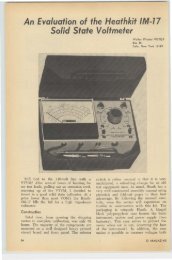
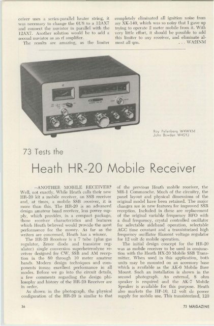
the Ileath Company." Assembly, wlrmg andtesting is nut difficult but plenty of time andcareful a ttention to detail are req uired.<strong>The</strong> instruction manual supplied with theHH-<strong>20</strong> was evaluated as the kit was ('011structed. This manual is quite comprehensi ve.consis ting of 64. 8}2" x II" pages. <strong>The</strong> manualcontains some 50 d rawings showing the assembly,wiring and installation of the receiver.Many of the more complex assemblyd rawings are printed on large, fold-out sheets.In addition, a sep arate "giant size" schematicdiagram is sup p lied for wall mounting. Construction,testing and installation arc coveredhy nearly 500 "check off" steps. <strong>The</strong>se instructionsarc arranged so as to be self checkingand it would indeed he difficult to goof anyp art of th e construction.Three minor e rrors, p ossibly typographical,were found in the instructions. Sin ce the e rrors arc obvious and Heath is correcting themwith an errata sheet, they will not be listedhere. <strong>The</strong> pictorials were remarkab ly goodand the onlv error noted was omission of asmall nylon washer in the gear drive assembly.All parts are shown in drawings in the fron tof the manna] so that even the relativelyinexperienced amateur should have little difficulryin identifying the components. Separate sections of the manuel arc de voted toinstallation a nd noise sup pression. All in all,th e manual is extremely good.Assembly, with minor excep tions, proceededaccord ing to the instruction s. <strong>The</strong>hermetic seal bushings on th e hottom of thecrystal filter wo uld not quite pass throughthe chassis clearance holes. A pass with a fi letook care of this problem. <strong>The</strong> same wastrue of the crystal socket mounting holes.\\!iring was easily accomplished . <strong>The</strong> flat,open ma in chassis pla te makes it a snap toachieve professional results. Despite the apparentcomplexity of the d ial drive assembly,it goes together quite easily. One ··E"retaining washer required bending to makea snug fi t in the shaft g roove. Only one caseof crowded assemb ly was noted. <strong>The</strong> audiooutp ut stage screen filter capacitor, a <strong>20</strong> mfd3.50 volt unit, barely fits as shown in the instructions.This is p rob ahly accounted for b ythe increase in value (uud physical size) overthe 8 mfd cap acitor shown in the prc-productionsche matic diagram.TIle completed receiver was carefullyc hecked before power was app lied . Everythingchecked out so power was applied, withno smoke resulting. Alignment was startedbut stopped when high pitched , audio feedbackwas noted at certain settings of the a udio@&W)TRSWITCH(TRANSM IT/ RECEIVE SWI TCH )MODEL 3818An electronic antenna changeover switch. Transmitter iscon tinuous ly connec ted to an tenna, antenna circ uit to reocelver is blocked durin g transmit. No switch contacts toarc or burn. SWitching is instantaneo us. Selectablebend-switching insures no loss in receiver sensitivity.Sub stantial gain in receiver sensi tivi ty results in mostinstall at io ns. Ideal for break-in operation on CW, SSBand AM. Bendswitch convenientty located on front. Threecoax connec tors are mounted on rear. Conservatively designedfo r full legal power. Operates from 11 5 volts,60 cycles. for 52· 75 ohm lines.Size 43/4 " x 4" x 5 1 /2"BARKER & WILLIAMSON, Inc.CQodiO ~ ll l ll Ullioo tioll £ quipntrllt ~1ICt ,q gQBRISTOL. P ENNS YLVANIA • STill_en 8 · 5 581Outstanding favorite for amateuu . .. Versatile combinationsfor industrials! Low VSWR - less tban 1.15:1rrom 0 to 500 mc. LOW LOSSES • • . High ContactPressures. LOW CROSS~TALK through use or patented"isolated connector" arrangement. HIGH POWER RATI NG. All coils encapsuled In epoxy res in tor q uieteroperation and resista nce to moisture.*.. UNCONDI TIONAL All Relays in weatherproolGUARANTEE lor boxes lor exterior Installation.one year. (We*will repair Ulaulty wltbln 1Ganged, multiple position,.ear.).wikh arrangement aVllllabl1ll or remotE- cont rol .electlonor a ntennas ... SE-e one 01 our100 dealers anddistributors In U.S. and Canada forl:a talo !,:"write :sbet-ts orSTANDARD RELAYS:DK60, DK60-G.DK60-2C and DK60-G2C -PRICED FRO.'.! ••• • $12.45DOW-KEY COMPANYThief River F.lI lIs, Minnesot.llDECEMBER 1962 41
gain control. Wiring, lead dress and componentswere checked with no luck. Finally,the .001 mfd capacitor across the primaryof the audio output transformer was replacedwith a .002 mfd unit. This proved to be apermanent fix. <strong>The</strong> oscillation was probablycaused by an unusual combination of extremetolerance components. How ever, to avoid thepossibility of this occurring in other receivers,we recommended to Heath that this changebe incorporated in all kits. <strong>The</strong> balance ofthe alignment went smoothly with no complicationsof any kind. Heath proved correctin their estimate of the time required to completethe kit, roughly 30 hours from start tofinish.<strong>The</strong>n came the pay-off-the "on the air"tests. Be advised that the performance of thereceiver is all that the specifications say it is.Sensitivity is extremely good, with receivernoise way down. <strong>The</strong> selectivity, as previouslymentioned, is a very fine compromise betweenthe requirements for SSB and A:\l reception.C\V is of course another story; a valid cornparisonis the CW performance of the Collin.75S-1 with SSB filters. Interference on oneside of the desired signal may be "droppedover the edge" of the crystal filter bandpassbut you have to live with what is left on theother side. \Vhile audio gain is adequate, thereis no great reserve.Tuning SSB signals is a pleasure. <strong>The</strong> dialratio is about the optimum compromise betweenSSB tuning requirements and the needto scan each amateur band in one receivertuning range. While a dual speed drive 'Wouldprohably be better, the resultant complexitymight prove prohibitive for kit construction.Although the gears are spring loaded, a slightroughness was noted in the tuning drive.Based on experience with previous Heathgear drives, this is expected to diminish withuse. <strong>The</strong> AGC system used in the <strong>HR</strong>-<strong>20</strong> isexcellent, with very effective action being obtainedon SSB signals. Use of selectable AGCtime constants really pays off in SS B reception.Frequency stability of the <strong>HR</strong>-<strong>20</strong> is extremelygood. After all, the stability requirementsfor mobile SSB reception are demandingto say the least. Total warm-up drift on<strong>20</strong> meters was 3 kc from an absolutely coldstart. After warm-up, the receiver is rockstable. <strong>The</strong> receiver was heterodyned with a10 meter signal; lifted a couple inches off thebench and dropped. <strong>The</strong> result was an instantaneous"gurgle" but the beat note didnot change. Try this test with other receivers;it is quite revealing.<strong>The</strong> frequency stability of the <strong>HR</strong>-<strong>20</strong> is ofgreat interest to the writers. It would appearpossible to convert the llR-<strong>20</strong> Receiverto an SSB transceiver, using a small inboardor outboard adaptor unit. <strong>The</strong> performanceof the receiver circuitry that would he usedin such a conversion has proved more thanadequate for the job. <strong>The</strong>refore, plans are inthe mill for this conversion. ]f it all pans out,this will be the subject of a future article.For a really rugged final test, the IIR-<strong>20</strong>was compared side by side with a Collins75S-1. <strong>The</strong> 75S-1 uses a system of sidebandselection where hoth the H FO and BFOfrequencies are shifted with a single switch.This feature, coupled with the better dialratio, made the 75S-1 easier and more convenientto operate. However, for actual perfonnance,the Heath receiver did not sufferin comparison. Dollar for dollar, the <strong>HR</strong>-<strong>20</strong>will be extremely difficult to beat. In theopinion of the writers, the <strong>HR</strong>-<strong>20</strong> is the bestbuy on the market today.... W4WKM and W4SYJS I'ECl l