Notes (PDF)
Notes (PDF)
Notes (PDF)

You also want an ePaper? Increase the reach of your titles
YUMPU automatically turns print PDFs into web optimized ePapers that Google loves.
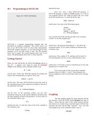
MAE 536Micro/Nano Electromechanical SystemsYong ZhuLecture 4 – Electrostatic Actuation and Sensing
Lecture Outline• Examples of Electrostatic Actuation/Sensing• Parallel Plate Actuator• Comb Drive Actuator• Capacitive Sensing• Differential Capacitive Sensing• Device Example: AccelerometerReading• Kovacs• Liu• Senturia2
Side-Drive MotorsSide view of SDMTop view of SDMFirst polysilicon motors were made at UCB (Fan, Tai, Muller), MIT, AT&TTypical starting voltages were >100V, operating >50V3
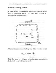
Fracture testing (surface micromachining)ActuatorComb Drive Actuatorsmovablecomb drivefixedcomb driveb)connecting beamFracture MechanicsSpecimennotchanchor padsCompression testing (bulk micromachining/SCREAM)4
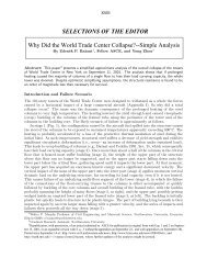
Electrostatic Skin Friction SensorsDifferential capacitive sensingwith comb-drive architecture-V+Vanchorsfloating platefolded beamsenseelectrodesfloating platedirectionof flowsense electrodecomb drive actuatortetherdirectionof flowDifferential capacitive sensingwith parallel plate architectureanchors5
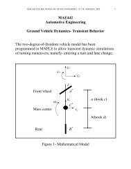
Electrostatic Actuation/SensingoscillatorComb drive resonatorComb drivenotchFracture and fatigue testing6
Capacitive Actuator (1)Consider a parallel plate capacitor with a spring connected to a movable plateThere are two ways of changing the energyin the capacitor: a) by changing the charge,b) by changing its geometry; hence, W(Q,x),with Q and x as state variables.kF extdWudQFextdxu: electrostatic potential [V]u+xF ext : external net force; x : gap-Total energy of the system is:W12C122( Q,x) Q K(x x0electricalelasticx 0 : position of the top plate when the spring is unloaded)2C Ax: capacitanceK: spring constantA: overlap area of the plates permittivity of the media between plates7
Wx1 Q2 ACapacitive Actuator (1)dWW (x2( )Q K(x x0) F extW)Qdx ( )Q;xW( )QdQxC AxxQAQCu: capacitancethe capacitance and spring constant are given by:2 W 1 1)x QC C(2x;2xW(2)KQK QNote that the external force is in equilibrium with the electrostatic force and thespring force. The electrostatic force does not depend on position “x”, why?Because in this formulation we assume that the charges in the plates areconstant!8
Since Q = Cu we have:21 K Au 1Wux ( , ) Cu ( xx0) Kx ( x0)2 2 2x2soCapacitive Actuator (1)2 2 22W1 Au( )u Fext K( xx20);x2 x2 2 Au W AuQ and ( )2 u K K3 uxxxW( ) xuIf we examine the equilibrium of the system, we have that K u = 0 correspondsto a bifurcation point. The corresponding voltage is3Kxu PIAFext1 Au2 x2PI2 K(x x0) 0From ;We getAt this voltage, the system becomes unstable, in other words, the top platecollapses to the bottom one. This system illustrates the so-called “pull-in”voltage concept.x 2 x30andu PI38Kx027A9
Capacitive Actuator (2)l pdFixed fingersMovable fingersModel for one pair of fingersK+qx-q dbIn this case, the total energy is2Q d KW ( x x0)2 a(b x)22d: finger separationa: finger depth10
The capacitor area A=ab and the overlap area is a(b-x) when motion xtakes placeFext2WQ d ( )Q K(x x0)2x2a(b x)Even at constant charge, the electrostatic force is dependent of position inthis case.At constant voltage:W C2u a(b x)K2 ( x x0)2d22WCu a )u K(x xx2dso F)KextuCapacitive Actuator (2)(02 W)x(2u K 0Independent of displacementx and proportional to u 2Therefore, no instability in the x-direction is possible in this actuator/sensor!However, there is an instability in the y-direction.For the case of an array of fingers, the electrostatic force is:a 2F array u N N: number of finger pairsd11
Capacitive Actuator (2)What are typical forces:• Surface micromachininga 2 m, d 2 m, for u = 15 VF ext 1 nNper finger pair1,000 fingers are needed to obtain 1 N force• DRIE or LIGAa 200 m, d 2 m, for u = 15 VF ext 100 nN = 0.1 Nper finger pair10,000 fingers are needed to obtain 1 mN forceNote: 0 = 8.854×10 -12 F/m, permittivity constant12
Layout of Comb DriveFolded beams(movable combsuspension)StationarycombMovingcombAnchorsGroundplateTang, Nguyen, Howe13
Scratch Drive Actuator (SDA)PlateBushingInsulatorSubstrate• Micro XYZ positioning stages(L. Y. Lin, et. al., 1997; Li Fan, et. al., 1997)• Self-assembly of MEMS devices(A. Terunobu, et. al., 1997; Y. Fukuta, et. al., 1997)• Free-space fiber optic cross/bar switch(Shi-Sheng Lee, et. al., 1997)14
SDA Operationdx1) Applied voltage bends SDAdownward2) When released, SDA returns tooriginal shape3) Reapplying voltage causes SDAto move a distance ‘dx’Caveat: sometimes they go backward!15
Capacitive Sensing: Parallel Plate Capacitorr0A AwlC Gap closing capacitord d dl 0 = 8.854×10 -12 r 1;F/mA wCwld f ( d)highly nonlinear2ddVCwlC d d2ddExample: A = 100×100 m 2 , d = 1 m, C 100 fFexamine under what conditions the gap closing capacitance behaves linearlyAAC(d) ; C(d d)dd d2C1 C23 Add2C(d d) C(d0) ( )d dd ( ) d o(d)[1 ( ) o(d)0 2 d d 0d2 dd d dC is linear in d if we can neglect terms of 0(d) 2 , e.g., for d 0 =1 m and d = 10 nm(1% of d 0 ),dd 2= 0.01; ( ) = 1×10 -4 , which can be neglecteddd 000003]16
Differential Gap Closing Capacitance+VC 1 = C 0 + CC 2 = C 0 - C-VQC AdV sense+VQ CV C V V) ; Q C Vsense ( ))( 1 1 sense;++++2 2( V----++++----V sense-VV senseVCV senseC1 C2Since Q 1 = Q 2 V C1 C2C 0AAC1 C0 C; C2 C0 C 2C C2 C1 ( )2 ( )1d0 dd0 dUsing Taylor expansion around d 0Second order term is dropped!2CA {[1 d0dd0d ( )d02 ...] [1dd0d ( )d02Ad ...]} [(2 ) o(d)d d003]17
Differential Gap Closing CapacitanceV senseVC CA differential capacitor exhibits a much better linearity and wouldwork for larger values of d in the linear regime.With current technology very small capacitances can bemeasured (fF). However, the so-called parasitic capacitance, C P ,complicates matters. In fact we have,VVsenseAd[(2 ) o(d)dC1C1 C C22 CTypical values if integrated with CMOS circuit:C 1 = 100 fF, C 1 –C 2 = 100 aF; C P = 1 pFVarious techniques to suppress parasitic capacitance includecharge sensing and bootstrapping an additional guard electrode.Successful commercial products using this technique includecapacitive pressure sensors and accelerometers.PA]/dd ( )302d000d018
Capacitive Sensing: Lateral Comb DriveLateral Comb DriveC(x)wxdCwxdConstant !C C ( ) xxVlwdw = 2 md = 2 mCx} = 8.854 × 10 -12 F/m 10 pF/mxOverlap distanceIf x = 1 nm;C 10 pF/m × 1 nm = 1 x 10 -18 F= 1 aF per finger;For 1,000 fingers, C for the sensor is 1 fF19
Differential Comb Drive Capacitorl pdV sense-V +VCwxFrom the previous derivation, V sense V ; C0Cd0ww2C C2 C1 [( x x)2 ( x x)1]C xddw xV sense xVx V ( )V sense V ( )dCx0xx: overlap finger distance; x: change in overlap distance20
ACCELEROMETERSDynamic equilibriumSpring F s =KxDamper F d =DvMxProof mass F m =MaMd2dtx2DdxdtKxFextMaa: acceleration to be sensedUndamped Natural Frequencyf RKMQuality FactorQ=energy stored per cycle/energy lost per cycleQMfDRRemarks:• Using Variational Methods, we can compute K• Squeeze-film effect provides D. This is more difficult to compute. Empirical.21
ACCELEROMETER TYPES• Strain Gage• Capacitive Sensing- Linear with and withoutforce feedback- Torsional• Tunneling(requires capacitive feedback)22
Strain Gauge AccelerometerOverall structure of an earlymicromachined piezoresistivestrain-gauge accelerometer.Detect acceleration as smallas 0.001 g; off-axis sensitivity10%.Procedure for double-sidedetching to release the siliconaccelerometer beam.Used to measure heart wallacceleration (biomedicalapplications, low g)23
AccelerometersCross-sectional view of amodern strain-gauge-typeaccelerometer manufacturedby Lucas NovaSensor.An asymmetric torsional plate design for a capacitive accelerometer.Sensitivity controlled by torsion bar24
Force-Balance Capacitive AccelerometerStructure and circuitry of Analog Devices ADXL-50 integrated, surface micromachinedaccelerometerDifferential capacitorsDRIE force-balanced accelerometerVery high off-axis stiffness;Larger capacitances;A relatively heavy proof mass.25
More on ADI AccelerometerV +tanchorV senseVC C 0PositionsensingV - tShuttle (proof mass)Self-TestMovable PartSchematic system diagram for “open-loop” systemSignalsource~Sensor-1DifferentialcapacitorALPFAmplifier DemodulatorLow-pass filterOutput26
AccelerometerAnalog Device accelerometerCMOSMEMS27
Calculation of Spring Constant: A Resonator4FFor fixed-guided beam:EIF 123L KFolded beams 1 2 2 2Each folded beam consists of twofixed-guided beams in seriesF FIf K 1 =K 2, K / 2FBK 1If the beam dimensions are L,h,w:3Resonant frequency is:fr1 2; F 1=F 2=F FK1 211FK221 F (KK1 K2 F() K K121FK FB1KK1 6EIK FB and K 4K3RFB32 LhI 12 w2Ehw / LM 0.3714Mp3For each folded beam:1/ 2andK R w 2Eh L 3224EIM P : mass of plate; M: mass of beamsL)28
Accelerometeranchort = 2.5 m; w = 2.5 m; L = 75 mE: Young’s modulus w K A 2Eh L For polysilicon, K A = 25.2 N/m3For the ADI accelerometer, mass of the movable structure is aboutM = 2.2×10 -10 1 Kkg; therefore, the resonant frequency f r 24.7 kHz.2M29
Lumped ModelDynamic equilibriumSpring F=kxDamper F=DvMxProof mass F=MaM2d x2dtDdxdtKxFextMaa: acceleration to be sensedWe can integrate the PDE in several ways. One such way is Laplace Transformation.Fst s f t e dt0; s: complex numberThe second order PDE results in a “transfer function” in s-space:H sXAs ss21D s MKM30
Lumped ModelAn important parameter in the design of accelerometers is themotion assuming the excitation frequency is much smaller than theresonant frequency of the system. In other words, static response:XstaticFKMaKfa2RHence the displacement depends only on the resonant frequencyand not directly on mass or spring constant independently. Thesecond implication is that if we need an accelerometer to respondquickly, we need high frequency and then X static is small. For examplefor a 50g accelerometer having a f R = 24.7 kHz, X static = 20 nm. Weneed a very good sensing capability and consistent with thisdisplacement.On the other hand, if f R = 1 kHz, the maximum displacement is about1.2 m. therefore, we realize there is a trade-off between bandwidth(time response) and sensitivity.31
Thermal Noise in Resistors32
Thermal Noise in Resistors33
AnalogySpring F=kxMxR=D L=MU ext C=1/k U cF extDamper F=DvM2d x2dt Df RQdxdt1 2MfD Kx Force spectral density :Proof mass F=MaRKMF2nfFext 4k MaNoise in Damper (Brownian motion of airmolecules):BTD2d uLCdtc2du RCdt1 1f R2LCQ u2nLfRR 4kBcTRfucUNoise in R (electron motion):ext34
Lumped ModelThe performance of the accelerometer is limited by thermal noise.The thermal energy is k B T/2, (k B is the Boltzman constant and T istemperature). The small proof mass is subjected to rather largemovement due to their thermal energy. It can be shown that the“total noise equivalent acceleration” is given byTNEA4kBTfQMRHence, to measure low acceleration levels, a large proof mass and ahigh quality factor are required!For the Analog Devices accelerometer, f R = 24.7 kHz, M = 2.2×10 -10kg, and Q = 5; hence, TNEA = 4.83×10 -3 m/sec 2 Hz or 0.5 mg/ HzIn a bandwidth of 0-1000 Hz,δaan, rms TNEA 1000Hz 32mg x 0.013 nmfIn practice other problems dominate, which are circuit noises,minimum stiffness to avoid stiction of proof mass, which result inan increase of f R .R35