AC-DC Single Output Power Module - TDK-Lambda
AC-DC Single Output Power Module - TDK-Lambda
AC-DC Single Output Power Module - TDK-Lambda

Create successful ePaper yourself
Turn your PDF publications into a flip-book with our unique Google optimized e-Paper software.
PFE500FBasic ConnectionL=50mmINPUTF11C1L1C2C3C4L2R1C52,3C6C7<strong>AC</strong>(L)PFE500F+s+v5C13 +C14 6C15C16+6C17OUTPUTInput Filter(For VCCI-classA)<strong>AC</strong>(N)-v-sTRIMAUXIOGPCENA+ON/OFFBASE-PLATE-ON/OFFCOMR +BC -BC5C82,3TFR1+C92,34C10C12+C11F1 <strong>AC</strong>250V 15A C12 2200pFR1 0.5W 470kΩ C13 0.033uFC1 <strong>AC</strong>250V 1uF (Film) C14 0.033uFC2 2200pF12V: 25V 1000uF (Elec.)C3 2200pF C15 28V: 50V 470uF (Elec.)C4 <strong>AC</strong>250V 1uF (Film) 48V: 100V 220uF (Elec.)C5 <strong>AC</strong>250V 1uF (Film) C16 100V 2.2uF (Ceramic)C6 2200pF12V: 25V 1000uF (Elec.)C7 2200pF C17 28V: 50V 470uF (Elec.)C8 450V 1uF (Film) 48V: 100V 220uF (Elec.)C9 450V 1uF (Film) TFR1 10Ω 139°C (Res., Thermal fuse)C10 450V 390uF (Elec.) L1 6mHC11 450V 390uF (Elec.) L2 6mH(*1) Use an external fuse of fast blow type for each unit.(*2) The allowable ripple current of capacitor must be more than 3A(rms).(*3) Put this capacitor near the terminal as close as possible.(*4) The maximum capacitance that can be used is less than 1200uF(Rated capacitance).Avoid the connection of capacitance which is more than above, else it will lead to module to damage.(*5) The inrush current at <strong>AC</strong> throw in can be suppressed by the external Resistor (Built-in thermal fuse) connected between the R and +BC terminals.(*6) If the ambient temperature is less than -20°C, use twice the recommended capacitor above.(*7) Refer to instruction manual for further details.・All contents are subject to change without notice.
PFE500FBlock DiagramPFHC+BC -BC<strong>DC</strong>/<strong>DC</strong> Converter<strong>AC</strong>(L)<strong>AC</strong>(N)RectifierPFHC circuitFilterInrush currentlimiting circuitSwitching circuitRectifier<strong>Output</strong> filterOVPOCP+V-VIutput voltagedetectorIutput currentdetector OCPOVPPFHC & BPSControl circuitBoost voltagedetectorBias powersupplyOTP(PFHC)OTP(<strong>DC</strong>-<strong>DC</strong>)Iutput voltagedetector(<strong>DC</strong>-<strong>DC</strong>)<strong>DC</strong>-<strong>DC</strong>Control circuitOCPSecondaryControl<strong>Output</strong> voltagedetectorIOGTRIM+S-SCOMPCENA+ON/OFF-ON/OFFAUXSwitching FrequencyPFHC circuit (fixed) : 100kHz<strong>DC</strong>/<strong>DC</strong> converter (fixed) : 230kHz (primary),460kHz (secondary)・All contents are subject to change without notice.
PFE500FSequence Time ChartInput Voltage(<strong>AC</strong>)390V<strong>DC</strong>(typ)BC Terminal Voltage(Boost Voltage)<strong>Output</strong> VoltageON/OFFComtrolIOGENAAUXHLHLHLHLHLInput LineONControlOFFControlONOVP TripControlOFFControlONOCPActiveOCPReleaseInput LineOFFInput LineONOTP TripControlOFFControlONV* voltage level: Refer to Application Notes “13.<strong>Power</strong> ON Signal”section.・All contents are subject to change without notice.
PFE1000FPFE1000F SpecificationsITEMS/UNITSInputMODEL PFE1000F-12 PFE1000F-28 PFE1000F-48Voltage Range (*2)(*3) V 85 - 265 V<strong>AC</strong>Frequency (*2) Hz 47 - 63<strong>Power</strong> Factor (*1)(*3) 0.95Efficiency (Typ) (*1) % 80 / 82 84 / 86Current (*1) A 9.8 / 4.8 13.6 / 6.6 13.4 / 6.5Inrush Current (Typ) (*1)(*3) A 20 / 40 peakNominal Voltage (*1) V<strong>DC</strong> 12 28 48Maximum Current A 60 36 21Maximum <strong>Power</strong> W 720 1008Voltage Setting Accuracy % +/-2<strong>Output</strong>Maximum Line Regulation mV 48 56 96Maximum Load Regulation mV 48 56 96Maximum Ripple & Noise (*3) mVp-p 120 280 480Voltage Adjustable Range % -20 / +20Over Current Protection (*4)(*5) 105% - 140%Over Voltage Protection (*5)(*1) At 100V<strong>AC</strong>/200V<strong>AC</strong> and maximum output power. (Baseplate Temperature = +25°C.)(*2) For cases where conformance to various safety specs (UL, CSA, EN) are required, input voltage range will be 100 - 240V<strong>AC</strong>(50/60Hz).(*3) External components are needed for operation. (Refer to basic connection and instruction manual.)(*4) Constant current limiting. (The unit automatically shutdown when left in OCP condition, with the output voltageless than the LVP level. Refer to instruction manual.)(*5) Reset : Line off or Control off. (Refer to instruction manual.)(*6) Refer to Instruction manual.(*7) Ambient Temperature min=-40°C(*8) Ratings - refer to Derating Curve.(*9) Heatsink has to be chosen according to Instruction manual.Derating Curve125% - 145% (Inverter shutdown method)Remote Sensing (*6) PossibleFunctionRemote ON/OFF Control (*6)PossibleParallel Operation (*6) PossibleSeries Operation (*6) PossibleOperating Temperature (*7)(*8) ℃ -40 - +100(Baseplate)Storage Temperature ℃ -40 - +100Operating Humidity % RH 20 - 95 (No Dewdrop)Storage Humidity % RH 10 - 95 (No Dewdrop)EnvironmentAt no operating, 10-55Hz (Sweep for 1min.)VibrationAmplitude 0.825mm constant (Maximum 49.0m/s²) X,Y,Z 1 hour eachShock196.1m/s²Cooling (*9) Conduction CooledInput-BaseplateWithstand VoltageIsolationIsolation ResistanceStandards Safety Standards: 2.5kV<strong>AC</strong>, Input-<strong>Output</strong> : 3.0kV<strong>AC</strong> for 1min.<strong>Output</strong>-Baseplate : 500V<strong>DC</strong> for 1min.<strong>Output</strong> to Baseplate 500V<strong>DC</strong> more than 100MΩ (25°C,70%RH)Approved by UL60950-1, CSA60950-1, EN60950-1Weight (Typ) g 500MechanicalSize (W x H x D) mm 100 x 13.4 x 160 (Refer to Outline Drawing)PFE1000F-12(720W)100Load(%)806040200-40 -20 0 20 40 60 80Baseplate Temperature(℃)100PFE1000F-28,48(1008W)100Load(%)80604085V<strong>AC</strong>≦Vin170V<strong>AC</strong>20170V<strong>AC</strong>≦Vin265V<strong>AC</strong>085-40 -20 0 20 40 60 80 100Baseplate Temperature(℃)・All contents are subject to change without notice.
PFE1000FPFE1000F Outline DrawingC L13.4±0.573.7147.7±0.55.0±0.5see note Dsee note A2.54see note E2.543.7C L12.019.043.7100.0±0.588.5±0.5<strong>AC</strong>(N)<strong>AC</strong>(L)<strong>AC</strong> (N)<strong>AC</strong> (L)PFE1000F-48INPUT : 100-240V<strong>AC</strong> 16AOUTPUT : 48VR +BC -BC21A<strong>AC</strong>-<strong>DC</strong>50/60HzEN6 0 9 50MADE IN JAPAN-SPC+ON/OFF-ON/OFFAUX-V-V-V+V+V+V+STRIMIOGEN<strong>AC</strong>OM-V-V-V+V+V+V2.5410.42±0.5 2.546.35 6.35 10.15 6.35 6.352.548.75R +BC -BCsee note C15.0 15.0 16.271.7see note B148.5±0.5160.0±0.5Lot No. sealNOTES:A: Model name, input voltage range, Nominal output voltage, NOTES Maximum : output current, country of manufacture and safety markingA: Model name, input voltage range, Nominal(C-UL-US, BSI & CE marking) are shown here in accordance with the specifications.output voltage, Maximum output current,B: M3 tapped holes 4 for customer chassis mounting (FG). country of manufacture and safety marking(C-UL-US, BSI & CE marking) are shownC: <strong>Output</strong> terminal : 6-Φ2here in accordance with the specifications.D: Input and Intermediate terminal : 5-Φ2B: M3 tapped holes 4 for customer chassisE: Signal pin (+S, -S, TRIM, ENA, IOG, AUX, +ON/OFF, -ON/OFF, mounting (FG). PC, COM) : 10-□0.64F: Unless otherwise specified dimensional tolerance : ±0.3 C: <strong>Output</strong> terminal : 6-2D: Input and Intermediate terminal : 5-2E: Signal pin (+S, -S, TRIM, ENA, IOG, AUX,+ON/OFF, -ON/OFF, PC, COM) : 10- 0.64F: Unless otherwise specified dimensionaltolerance : ±0.310・All contents are subject to change without notice.
PFE1000FBasic ConnectionL=50mmINPUTF11C1L1 L2 L3C2C4 C5C3C6C7R1C82,3<strong>AC</strong>(L)PFE1000F+s+v3C15 + C17C16 6 C18+6C19OUTPUT<strong>AC</strong>(N)-v-sTRIMAUXIOGBASE-PCPLATEENA+ON/OFF-ON/OFFCOMR +BC -BCC92,3C10 2,3Input Filter(For VCCI-classA)TFR25TFR1 5++++C11 4C12 4C13 4C14 4F1 F25AH250V C15 0.033uFC1 <strong>AC</strong>250V 1uF (Film) C16 0.033uFC2 470pF12V:25V 1000uF (Elec.)C3 470pF C17 28V:50V 470uF (Elec.)C4 <strong>AC</strong>250V 1uF (Film) 48V:100V 220uF (Elec.)C5 <strong>AC</strong>250V 1uF (Film) C18 100V 2.2uF (Ceramic)C6 4700pF12V:25V 1000uF (Elec.)C7 4700pF C19 28V:50V 470uF (Elec.)C8 <strong>AC</strong>250V 1uF (Film) 48V:100V 220uF (Elec.)C9 450V 1uF (Film) R1 0.5W470kΩC10 450V 1uF (Film) TFR1 5.1Ω139℃ (Res., Thermal fuse)C11 450V 390uF (Elec.) TFR2 5.1Ω139℃ (Res., Thermal fuse)C12 450V 390uF (Elec.) L1 2mHC13 450V 390uF (Elec.) L2 2mHC14 450V 390uF (Elec.) L3 2mH(*1) Use an external fuse of fast blow type for each unit.(*2) The allowable ripple current of capacitor must be more than 3A(rms).(*3) Put this capacitor near the terminal as close as possible.(*4) The maximum capacitance that can be used is less than 2300uF(Rated capacitance).Avoid the connection of capacitance which is more than above of else it will lead to module damage.(*5) The inrush current at <strong>AC</strong> throw in can be suppressed by the external Resistor (Built-in thermal fuse) connected between the R and +BC terminals.(*6) If the ambient temperature is less than -20°C, use twice the recommended capacitor above.(*7) Refer to instruction manual for further details.・All contents are subject to change without notice.11
PFE1000FBlock DiagramPFHC+BC -BC<strong>DC</strong>/<strong>DC</strong> Converter<strong>AC</strong>(L)<strong>AC</strong>(N)RectifierPFHC circuitFilterInrush currentlimiting circuitSwitching circuitRectifier<strong>Output</strong> filterOVPLVPOCP+V-VIutput voltagedetectorIutput currentdetector OCPOVPPFHC & BPSControl circuitBoost voltagedetectorBias powersupplyOTP(PFHC)OTP(<strong>DC</strong>-<strong>DC</strong>)Iutput voltagedetector(<strong>DC</strong>-<strong>DC</strong>)<strong>DC</strong>-<strong>DC</strong>Control circuitOCPSecondaryControl<strong>Output</strong> voltagedetectorIOGTRIM+S-SCOMPCENA+ON/OFF-ON/OFFAUXSwitching FrequencyPFHC circuit (fixed) : 100kHz<strong>DC</strong>/<strong>DC</strong> converter (fixed) : 230kHz (primary),460kHz (secondary)12・All contents are subject to change without notice.
PFE1000FSequence Time ChartInput Voltage(<strong>AC</strong>)390V<strong>DC</strong>(typ)BC Terminal Voltage(Boost Voltage)<strong>Output</strong> VoltageON/OFFComtrolHLHLV*V*OVP Trip PointOCP Trip PointLVP Trip PointV**IOGHLENAHLAUXHLInput LineONControlOFFControlONOVP TripControlOFFControlONOCPActiveLVP TripControlOFFControlONInput LineOFFInput LineONOTP TripControlOFFControlONV* voltage level: Refer to Application Notes “13.<strong>Power</strong> ON Signal”section.V** voltage level: Refer to Application Notes “6.Over Current Protection”section.・All contents are subject to change without notice.13
PFE500F・1000F SERIESPFE500F, 1000F SERIES Instruction ManualBEFORE USING THE POWER SUPPLY UNITBe sure to read this instruction manual thoroughly before usingthis product. Pay attention to all cautions and warnings beforeusing this product. Incorrect usage could lead to an electricalshock, damage to the unit or a fire hazardDANGER● Never use this product in locations where flammable gas orignitable substances are present.WARNING● Do not make unauthorized changes to power supply unit, otherwiseyou might have electric shock and void your warranty.● Do not touch this unit and the internal components in operationor shortly after shut down. They might have high voltageor high temperature and as the unit dissipates its heat so thesurface of the unit is hot. You might receive electric shock orburn.● When the unit is operating, keep your hands and face awayfrom it; you might be injured by an accident.● Do not use unit under unusual condition such as emission ofsmoke or abnormal smell and sound etc. It might cause fireand electric shock. In such case, please contact us; do notrepair by yourself, as it is dangerous for the user.● Do not drop or insert anything into unit. It might cause failureand fire.● Do not operate these units under condensation condition. Itmight cause fire and electric shock.CAUTION● As a component part, compliance with the standard will bebased upon installation in the final application. This productmust be installed in a restricted access location, accessibleto authorized competent personnel only. These <strong>AC</strong> to <strong>DC</strong>converters have reinforced insulation between the input andthe output. The outputs of these products are energy hazards.All models with an output greater than 48V model areconsidered to be non-SELV. As such, the instructions for usemust refer to these energy hazardous outputs and Non-SELVoutputs in that the outputs must not be accessible to theoperator. The installer must also provide protection againstinadvertent contact by a service engineer.● The equipment has been evaluated for use in a Pollution Degree2 environment.● This power supply is primarily designed and manufactured tobe used and enclosed in other equipment.● Confirm connections to input/output terminals and signal terminalsare correct as indicated in the instruction manual.● Attach a fast acting external fuse to each module to ensuresafety operation and compliance to each safety standard approval.The recommended input fuse rating within the instructionsmanual. The breaking capacity and voltage rating of thisfuse might be subject to the end use application.● Input voltage, <strong>Output</strong> current, <strong>Output</strong> power, ambient temperatureand ambient humidity should be used within specifications,otherwise the unit will be damaged.● For application equipment, which requires very high reliability(Nuclear related equipment, traffic control equipment, medicalequipment, etc.), please provide fail safety function in theequipment.● Do not use the product in environment with strong electromagneticfield, corrosive gas and conductive substance.● Do not operate and store this unit at an environment wherecondensation occurs. In such case, waterproof treatment isnecessary● Never operate the unit under over current or shorted conditionsfor 30 seconds or more and out of Input Voltage Rangeas specification. Insulation failure, smoking, burning or otherdamage might occur to the unit.● The output voltage of this power supply unit is consideredto be a hazardous energy level (The voltage is 2V or moreand the electric power is 240VA or more). Prevention fromdirect contact with output terminal is highly necessary. Whileinstalling or servicing this power supply unit, avoid droppingtools by mistake or direct contact with output terminal. Thismight cause an electrical shock. While repairing this powersupply unit, the <strong>AC</strong> input power must be switched off and theinput and output voltage should be level.● To maintain the SELV output for outputs less than 28V<strong>DC</strong>,under fault conditions, the output must be connected to earthin the final application.● The application circuits and their parameter are for referenceonly. Be sure to verify effectiveness of application circuitsand their parameters before finalizing circuit design.● Do not inject abnormal voltage to output terminal and signalterminal from the outside. The injection of reverse voltage orover voltage exceeding nominal output voltage to output terminalsmight cause damage to internal components.● This information in this document is subject to change withoutprior notice. For actual design-in, please refer to the latestpublications of data sheet, etc., for the most up-to datespecifications of the unit.● Design the board of an application circuit implementing thisproduct in consideration of components layout, pattern layoutand pattern width.● No part of this document might be copied or reproduced inany form without prior written consent of <strong>TDK</strong>-<strong>Lambda</strong>.Note : CE MARKINGCE Marking when applied to a product covered by this handbookindicates compliance with the low voltage directive (2006/95/EC) in that it complies with EN60950-1.14・All contents are subject to change without notice.
PFE500F・1000F SERIES1. Terminal Explanation■PFE500F Series<strong>AC</strong>(N) -V<strong>AC</strong>(L)Name Plate+V-SPC+STRIM+ON/OFFIOG-ON/OFFENAAUXCOMR +BC -BC[Input side terminals][<strong>Output</strong> side terminals]<strong>AC</strong>(L) : Input terminal live line<strong>AC</strong>(N) : Input terminal neutral line+V : +<strong>Output</strong> terminal-V : -<strong>Output</strong> terminal+BC :-BC :R :+Boost voltage terminal-Boost voltage terminalExternal inrush current limiting resistorterminal+S : +Remote sensing terminal-S : -Remote sensing terminalPC : <strong>Output</strong> current balance terminalTRIM : <strong>Output</strong> voltage trimming terminalIOG : Inverter operation good terminalENA : <strong>Power</strong> on signal terminal+ON/OFF : +ON/OFF control terminal-ON/OFF : -ON/OFF control terminalAUX : Auxiliary power supply terminal for external circuitsCOM : Common ground terminal・Baseplate can be connected to FG through M3 mounting tapped holes.・Consider contact resistance when connecting <strong>AC</strong> (L), <strong>AC</strong> (N), R, +BC, -BC, +V, -V.・Note that +BC and -BC terminals is a primary voltage with high voltage (390V<strong>DC</strong>).Do not connect load to these terminals. It might result in power module damage.・All contents are subject to change without notice.15
PFE500F・1000F SERIES■PFE1000F Series<strong>AC</strong>(N)-SPC+ON/OFF+STRIMIOG-ON/OFFENA<strong>AC</strong>(L)Name PlateAUX-V-V-VCOM+V+V+VR +BC -BC[Input side terminals][<strong>Output</strong> side terminals]<strong>AC</strong>(L) : Input terminal live line<strong>AC</strong>(N) : Input terminal neutral line+V : +<strong>Output</strong> terminal-V : -<strong>Output</strong> terminal+BC :-BC :R :+Boost voltage terminal-Boost voltage terminalExternal inrush current limiting resistorterminal+S : +Remote sensing terminal-S : -Remote sensing terminalPC : <strong>Output</strong> current balance terminalTRIM : <strong>Output</strong> voltage trimming terminalIOG : Inverter operation good terminalENA : <strong>Power</strong> on signal terminal+ON/OFF : +ON/OFF control terminal-ON/OFF : -ON/OFF control terminalAUX : Auxiliary power supply terminal for external circuitsCOM : Common ground terminal・Baseplate can be connected to FG through M3 mounting tapped holes.・Consider contact resistance when connecting <strong>AC</strong> (L), <strong>AC</strong> (N), R, +BC, -BC, +V, -V.・Note that +BC and -BC terminals is a primary voltage with high voltage (390V<strong>DC</strong>).Do not connect load to these terminals. It might result in power module damage.16・All contents are subject to change without notice.
PFE500F・1000F SERIES2. Explanations on Specifications Input Voltage RangeInput voltage range is indicated below. Take care not toapply input voltage which is above this specified range orunder this specified range for more than 30 seconds. Nor● Basic Connectionshould a <strong>DC</strong> input voltage be applied as this would resultinto power module damage.Input Voltage Range : <strong>Single</strong> Phase 85 to 265V<strong>AC</strong>Line Frequency Range : 47 to 63HzL=50mmFuse L1 L2C2C1C4 R1 C5C3C6C7<strong>AC</strong>(L)+S+VC13 + C15C14 C16++ C17LoadInput Filter(For VCCI-classA)TFR1Fig. 1-1-(1) Basic Connection for PFE500F SeriesC8C9C10+C11+C12-L=50mmFuse L101 L102 L103C102C106C101C104 C105 R101 C108C103C107<strong>AC</strong>(L)+S+VC115+ C117C116 C118+ C119+LoadInput Filter(For VCCI-classA)<strong>AC</strong>(N)-VPFE500F-STRIMAUXIOGPCENA+ON/OFFBASE-PLATE-ON/OFFCOMR +BC -BC<strong>AC</strong>(N)-VPFE1000F-STRIMAUXIOGPCENA+ON/OFFBASE-PLATE-ON/OFFCOMR +BC -BCTFR101TFR102C109C110C111+C112+C113+C114+-Fig. 1-1-(2) Basic Connection for PFE1000F SeriesNote) To meet the surge immunity, evaluate the addition of the surge protection components.Refer to separate document“PFE500F Series IEC Data”and“PFE1000F Series IEC Data”.・All contents are subject to change without notice.17
PFE500F・1000F SERIESF1 : External Input FuseThis power module has no internal fuse. Use external fuseto acquire each Safety Standard and to further improvesafety. Further, Fast-Blow type fuse must be used per onemodule. Also, in-rush surge current flows during line throwin.Be sure to check I 2 t capability of external switch andfuse.Recommended External FusePFE500F : F15AH, 250VPFE1000F : F25AH, 250VNote)Select fuse based on rated voltage, rated current and breakingcapacity.(1)Voltage Ratings100V<strong>AC</strong> line : <strong>AC</strong>125V200V<strong>AC</strong> line : <strong>AC</strong>250V(2)Current RatingsRated current is selected by the maximum inputcurrent based on operating conditions and can becalculated by the following formula.PoutIin (max)=(Arms) (Formula 1-1)Vin×Eff×PFIin (max):Maximum Input CurrentPout : Maximum <strong>Output</strong> <strong>Power</strong>Vin : Minimum Input VoltageEff : EfficiencyPF : <strong>Power</strong> Factor(3)Breaking CapacityThe breaking capacity may be subject to the enduse application. Please select a suitably ratedbreaking capacity fuse for end use application.For Efficiency and <strong>Power</strong> Factor values, refer toseparate document “PFE500F Series EvaluationData”and “PFE1000F Series Evaluation Data”.C1, C4, C5 : 1uF (Film Capacitor)C101, C104, C105, C108 : 1uF (Film Capacitor)Ripple current flows through this capacitor. When selectingcapacitor, be sure to check the allowable maximum ripplecurrent rating of this capacitor. Verify the actual ripple currentflowing through this capacitor by doing actual measurement.Recommended Voltage Rating : 250V<strong>AC</strong>Note)Connect C5, C108 as near as possible towards the inputterminals of this power module.Audible noise may occur depending on type of film capacitor.L1, L2 : 6mHL101, L102, L103 : 2mHAdd common mode choke coil to conform to EMI/EMSstandard. When using multiple modules, connect coil toeach module.Note) Depending on the input filter used, noise might increase orpower module might malfunction due to filter resonance.C2, C3, C6, C7, C12: 2,200pF (Ceramic Capacitor)C102, C103 : 470pF (Ceramic Capacitor)C106, C107 : 4,700pF (Ceramic Capacitor)Connect ceramic capacitor to conform to EMI/EMS standard.Be sure to note the leakage current of your equipment whenconnecting this capacitor.High withstand voltage are applied across this capacitor dependingon the application. Select capacitors with high withstandvoltage rating.R1, R101 : 470kohmConnect bleeder resistor across <strong>AC</strong>(L) and <strong>AC</strong>(N) terminals.C8, C9 : 1uF (Film Capacitor)C109, C110 : 1uF (Film Capacitor)Ripple current flows through this capacitor. When selectingcapacitor, be sure to check the allowable maximum ripplecurrent rating of this capacitor. Verify the actual ripple currentflowing through this capacitor by doing actual measurement.Recommended Voltage Rating : 450V<strong>DC</strong>Note) Select Capacitor with more than 3A (rms) rating. ConnectC8, C9, C109, C110 as near as possible towards the terminalsof this power module.C10, C11: 390uF (Electrolytic Capacitor)C111, C112, C113, C114 : 390uF (Electrolytic Capacitor)Refer to “Selection Method of External Bulk Capacitor forBoost Voltage”.Allowable External Capacitance at nominal capacitor valueis shown below.Recommended Voltage Rating : 450V<strong>DC</strong>Recommended Total Capacitor :390uF to 1,200uF (PFE500F Series)780uF to 2,300uF (PFE1000F Series)Note)1. Do not connect capacitors with more than the abovecapacitance value as this might result in power moduledamage.2. When using module between 390uF – 600uF forPFE500F Series, 780uF – 1,200uF for PFE1000F Seriestotal capacitor value, it is necessary to reduce outputpower as shown in Fig1-3.3. When using module below -20 deg C ambient temperature,<strong>AC</strong> ripple of boost voltage, output ripple voltage and startup characteristics might be affected by ESR characteristicsof the bulk capacitors.Therefore, be sure to verify characteristics by actualevaluation.C13, C14, C115, C116 : 0.033uFConnect ceramic or film capacitor to conform to EMI/EMSstandard and to reduce output spike noise voltage.Note)High Voltage is applied across this capacitor during withstandvoltage test depending on the application.Connect C13, C14, C115, C116 as near as possible towardsthe terminals of this power module.18・All contents are subject to change without notice.
PFE500F・1000F SERIESC15, C117 : Refer to Table 1-1To reduce output ripple voltage and to stabilize operation,connect electrolytic capacitors across +V and –V terminals.Note)Connect C15, C117 as near as possible to the +V and -Vterminals of this power module.Vout12V28V48VC15 , C11725V 1,000uF50V 470uF100V 220uFTable 1-1 C15, C117:Recommended external capacitanceC16, C118 : 2.2uF (Ceramic Capacitor)Connect ceramic capacitor within 50mm from the output terminals+V and -V of the power module to reduce output spikenoise voltage.Also, note that output spike noise voltage might vary dependingon the wiring pattern of the printed circuit board.C17, C119 : Refer to Table 1-2Connect C17, C119 within 50mm from the output terminals+V and -V of the power module to stabilize operationand to reduce output ripple noise voltage.Note that the output ripple and line turn off characteristicsof the power module might be affected by the ESR andESL of the electrolytic capacitor.Also, note that output ripple voltage might vary dependingon the wiring pattern of the printed circuit board.Fluctuation in output voltage due to sudden load changeor sudden input voltage change can be reduced by increasingexternal output capacitor value.Vout12V28V48VC17 , C11925V 1,000uF50V 470uF100V 220uFTable 1-2 C17, C119:Recommended external capacitanceNote) 1. Use low-impedance electrolytic capacitors with excellenttemperature characteristics.(Nippon Chemi-con LXY Series or equivalent)(Nichicon PM Series or equivalent)2. For module operation at ambient temperature -20 deg Cor less, output ripple voltage might be affected by ESRcharacteristics of the electrolytic capacitors. Increase thecapacitor values shown in Table 1-1 and 1-2 accordingto the table below.Vout12V28V48VC15 , C17 , C117 , C11925V 1,000uF x 2 parallel50V 470uF x 2 parallel100V 220uF x 2 parallelTable 1-3 C15, C17, C117, C119 :Recommended external capacitance(Ambient Temperature < -20 deg C)3. Take note of the allowable maximum ripple current of theelectrolytic capacitor used. Especially, for sudden loadcurrent changes, verify actual ripple current and makesure that allowable maximum ripple current is not exceeded.●Selection Method of External Bulk Capacitorfor Boost VoltageBoost voltage bulk capacitor is selected by ripple voltage,ripple current and output hold-up time.Select capacitor value such that boost voltage ripplevoltage does not exceed 15Vp-p.Note) When ambient temperature is -20 deg C or less,ripple voltage of the boost voltage might increase dueto ESR characteristics. Therefore, verify above characteristicsby actual evaluation.For output hold-up time, refer to separate document“PFE500F Series Evaluation Data”or “PFE1000FSeries Evaluation Data”and use appropriate capacitorup to 1,200uF maximum for PFE500F Series,2,300uF maximum for PFE1000F Series. (It is recommendedthat verification should be done throughactual evaluation).For allowable ripple current value, refer to Fig. 1-2 andselect a capacitor with higher ripple current rating.・All contents are subject to change without notice.19
PFE500F・1000F SERIESRipple Current(mA rms)2000160012008004000100V<strong>AC</strong>200V<strong>AC</strong>0 20 40 60 80 100<strong>Output</strong> <strong>Power</strong>(%)1001200uF80604020390uFTbp:25℃00 200 400 600 800 1000 1200Load Current(%)Bulk Cap.(u)Fig. 1-2-(1) Ripple current value for PFE500F Series(A value per one of Fig. 1-1-(1) connection)Fig. 1-3-(1) <strong>Output</strong> <strong>Power</strong> v.s. Boost Voltage BulkCapacitance For PFE500F SeriesRipple Current(mA rms)2000160012008004000100V<strong>AC</strong>200V<strong>AC</strong>0 20 40 60 80 100<strong>Output</strong> <strong>Power</strong>(%)1002300uF80604020780uFTbp:25℃00 500 1000 1500 2000 2500Load Current(%)Bulk Cap.(u)Fig. 1-2-(2) Ripple current value for PFE1000F Series(A value per one of Fig. 1-1-(2) connection)Fig. 1-3-(2) <strong>Output</strong> <strong>Power</strong> v.s. Boost Voltage BulkCapacitance For PFE1000F SeriesThe recommended boost voltage bulk capacitor valuerange is 390uF-1,200uF for PFE500F Series, 780uF-2,300uF for PFE1000F Series.When using with reduced the bulk capacitor value, it isnecessary to reduce output power as shown in Fig1-3.Note that reducing the bulk capacitance affects outputhold-up time, dynamic line response and dynamic load responsecharacteristics.It is recommended that verification should be done throughactual evaluation.TFR1 : 10 to 100 ohmTFR101, TFR102 : 10 to 50 ohm (Total value)By connecting resistor across R and +BC terminals as shownin Fig. 1-1, in-rush current during line throw-in can be suppressed.Failures due to in-rush current such as melting ofexternal fuse, welding of relay or switch connecting joints orshutdown of No-Fuse Breakers (NFB) might occur. Therefore,select TFR1, TFR101, TFR102 in consideration of the surgecurrent capability of the external components. (TFR1, TFR101,TFR102 are recommended to use the Thermal Fuse Resistor.)Note) 1.Do not connect resistors that is out of range from thevalues shown above as this might result in power moduledamage.2.Note that this module will not operate without this externalresistor.●Selection Method of External Resistor(1)Calculating Resistance Value for External ResistorResistance can be calculated by the formula below.R: Resistance Value for External resistorVin : Input Voltage converted to <strong>DC</strong> value=Input Votlage (rms)×√2Irush : Input surge current value(2)Required Surge Current RatingSufficient surge current withstand capability isrequired for external resistor.Required Surge Current Rating can be selected byI 2 t. (Current squared multiplied by time)I 2 t : Current-squared multiplied by timeCo : Boost Voltage Bulk CapacitanceVin : Input Voltage converted to <strong>DC</strong> valueRR= VinIrushI 2 t=Co×Vin22×RΩ (Formula 1-2)(A 2 s) (Formula 1-3)=Input Voltage (rms)×√2: Resistance Value for External Resistor <strong>Output</strong> Voltage Adjustment Range(TRIM terminal)<strong>Output</strong> voltage can be adjusted within the range below byconnecting fixed and variable resistors or applying external20・All contents are subject to change without notice.
PFE500F・1000F SERIESvoltage.However, take care not to exceed the output voltage rangeshown below because OVP function will activate.In the PFE1000F Series, be careful not to drop from thefollowing range, because a Low Voltage Protection (LVP)function will be activate.<strong>Output</strong> Voltage = TRIM Terminal Voltage x Nominal <strong>Output</strong>+Voltage<strong>Output</strong> Voltage Adjustment Range :+++/-20% of the typical voltage rating+ +LoadWhen increasing or decreasing output voltage, it must notexceed maximum output current and power.Even if the output voltage is adjusted using external circuitshown in Fig. 2-1, remote sensing can be done. For detailson Remote Sensing function, refer to“9. Remote Sensing”.--TRIM-+-<strong>Output</strong> Voltage Adjustment using Fixed and VariableResistorsExternal resistor (R1) and variable resistor (VR) values, aswell as, circuit connection is shown below.For this case, remote programming of the output voltagecan be done through the remote programming resistor VR.Be sure to connect the remote programming resistor between+S and +V terminalsFig. 2-2 <strong>Output</strong> Voltage Adjustmentby applying external voltageFor applications other than the above, refer to the TRIMcircuit as shown in fig.2-3 and determine external circuitand components values.12V 28V 48VR1 18k 18k 18kVR 10k 20k 50kError amplifier+Sunit:[ohm]External Resistor : Tolerance +/-5% or lessVariable Resistor : Total Tolerance +/-20% or lessRemain Resistance 1% or lessTable 2-1External Resistor and Variable Resistor Value(For +/-20% <strong>Output</strong> Adjustment)7.32kΩ1.225VReferencevoltage32.4kΩ1kΩTRIM-SVRFig.2-3 Internal TRIM Circuit (For the Reference)++--TRIM+ +R1Fig. 2-1 External Resistor Connection Example<strong>Output</strong> Voltage Adjustment by applying externalvoltageBy applying external voltage at the TRIM terminal, outputvoltage can be adjusted within the same output voltageadjustment range as the output voltage adjustment byexternal resistor or variable resistor. For this case, outputvoltage can be determined by the formula shown below.+-Load Maximum Ripple and NoiseThis value is measured according to the description belowin accordance with JEITA-9131B(Section 7.16, 7.17 and7.18).In the basic connection shown in Fig. 1-1, additionalconnection shown in Fig. 3-1 is done for measurement.Capacitor (Ceramic Capacitor : 2.2µF and ElectrolyticCapacitor : Refer to Table 1-2) must be connected within50mm from the output terminals. Then, connect coaxialcable with JEITA attachment across the ceramic capacitorelectrodes. Use 100MHz bandwidth oscilloscope orequivalent.Also, note that output ripple voltage and output spike noisevoltage might vary depending on the wiring pattern of theprinted circuit board.In general, output ripple voltage and output spike noisevoltage can be reduced by increasing external capacitance・All contents are subject to change without notice.21
PFE500F・1000F SERIESFig. 3-1<strong>Output</strong> Ripple Voltage (including Spike Noise)Measurement Method Maximum Line RegulationMaximum line regulation is defined as the maximum outputvoltage change when input voltage is gradually changed(Steady-State) within specification range. Maximum Load RegulationMaximum load regulation is defined as the maximum outputvoltage change when output load current is graduallychanged (Steady-State) within specification range.When using power module in dynamic load mode, audiblesound could be heard from the power module or largeoutput voltage change might occur. Make prior evaluationthoroughly before using this power module. Over Current Protection (OCP)This module is equipped with OCP function.Constant current limiting with automatic recovery forPFE500F Series. <strong>Output</strong> will automatically recover whenshort circuit or overload condition is released.Constant current limiting with delay shutdown forPFE1000F Series. <strong>Output</strong> will be shutdown when outputabout under 70% by short circuit or overload conditionthat continue about 0.5s. When the shutdown function activates,first cut off input line and verify that boost voltagehas dropped down to 20V or less. Then, recover outputby recycling input line. In other method, reset to ON/OFFcontrol. OCP value is fixed and cannot be adjusted externally.+V-V+50mmNote that continuous short circuit or overload conditionmore than 30s, might result in power module damage. Over Voltage Protection (OVP)This module is equipped with OVP function. This value isset between 125% to 145% of nominal output voltage.When the OVP function activates, first cut off input lineand verify that boost voltage has dropped down to 20V orless. Then, recover output by recycling input line. In othermethod, reset to ON/OFF control. OVP value is fixed andcannot be set externally.+Wires must be as short as possible1.5m 50ΩCoaxial CableJEITAAttachmentR:50ΩC:4700pFRC+Load-Oscilloscope Over Temperature Protection (OTP)This module is equipped with OTP function. This functionactivates and shuts down the output when ambienttemperature or internal temperature abnormal rises. OTPactivates at following baseplate temperature.PFE500F-12: 90 to 115 deg CPFE500F-28, 48 : 105 to 130 deg CPFE1000F-*: 105 to 130 deg CWhen OTP function operates, output can be recoveredby cooling down the baseplate sufficiently and letting theboost voltage drop down to 20V or less before recyclingthe input line. In other method, reset to ON/OFF control. Remote Sensing (+S, -S terminals)This module has remote sensing terminals to compensatefor voltage line drop from the output terminals to the outputload. When remote sensing is not required, (local sensing)short +S to +V and -S to -V terminals respectively.Note that line drop (voltage drop due to wiring ) compensationvoltage range must be such that the output voltageis within the output voltage adjustment range and that thevoltage between -V and -S must be within 0.5V.Consider power loss due to line drop and use power modulewithin the maximum allowable output power. Reducethe effect of noise to the remote sensing line by using ashield line, a twist pair, or a parallel pattern, etc.When remote sensing line is long, add the electrolytic capacitoras shown in Fig 9-1.++--++--+++++Fig. 9-1 Remote Sensing is usedStabilize the output voltageat output terminal+Stabilize the output voltageat load terminalTwist pairFig. 9-2 Remote Sensing is not used (Local Sensing)++-+-LoadLoad22・All contents are subject to change without notice.
PFE500F・1000F SERIES ON/OFF Control(+ON/OFF, -ON/OFF terminal)AUXThis module is equipped with ON/OFF control function.Without turning the input supply on and off, the output canbe enabled and disabled using this function.The ON/OFF control circuit is isolated from input circuit ofthe power supply by photo-coupler.Fig. 10-1 and Fig. 10-2 is connection example of ON/OFF control. When the ON/OFF control is not used, short+ON/OFF to AUX and -ON/OFF to COM terminals respectively.11V4.7kCOM+ON/OFF-ON/OFFAUX11VFig. 10-3 ON/OFF Control Connection Example 3(ON/OFF Control is not used)4.7kCOM+ON/OFFRExternalvoltage Series OperationSeries operation is possible for PFE500F Series andPFE1000F Series. Connections shown in Fig. 11-1 andFig. 11-2 are possible.-ON/OFFFig. 10-1 ON/OFF Control Connection Example 1(ON/OFF Control by External Voltage)Select the external voltage and external resistance, as theON/OFF terminals current is shown below.ON/OFF terminal current2.5mA (+/-0.5mA)Less than 0.15mAOFF<strong>Output</strong> VoltageONOFFTable 10-1 Recommended ON/OFF Terminal CurrentON+S+V-V-S+S+V-V-S++Fig. 11-1 Series Operationfor High <strong>Output</strong> Voltage Applications+-LoadAUX+S11V+V++Load-V-COM-S4.7k+ON/OFFONOFF+S+V-V++Load--ON/OFF-SFig. 11-2 +/-<strong>Output</strong> Series ApplicationsFig. 10-2 ON/OFF Control Connection Example 2(ON/OFF Control by Built-in AUX) Parallel Operation (PC terminal)By connecting the PC terminal of each power module,output current can be equally drawn from each module. Amaximum of 6 units of the same model can be connected.・All contents are subject to change without notice.23
PFE500F・1000F SERIESHowever, maximum output current is derated by paralleloperation units as shown in Table 12-1.Note that usage of power module at out-of-rated conditionmight result in power module temperature abnormal rise ordamage.Parallel unitsMaximum output current~ 3 units90% of nominal output current4 ~ 6 units 85% of nominal output currentTable 12-1 Condition for Parallel OperationSet the accuracy of the output voltage within +/-1% whenadjust the output voltage for parallel operation.When adjust the output voltage by applying external voltageat the TRIM terminal, insert a about 10k ohm resistorbetween TRIM terminal and external source.Moreover, external circuits are necessary for TRIM terminalat each individual module.PFE500F・1000F-12 : 6V (TYP)PFE500F・1000F-28 : 15V (TYP)PFE500F・1000F-48 : 28V (TYP) I.O.G signal (IOG terminal)Normal or abnormal operation of the power module can bemonitored by using the IOG terminal. <strong>Output</strong> of this signalmonitor is located at secondary side (output side) and isan open collector output.This signal is LOW when inverter is normally operating andHIGH when inverter stops or when inverter is operating abnormally.(maximum sink current is 5mA, maximum appliedvoltage is 35V)Ground for the IOG terminal is the COM terminal.Also note that IOG becomes unstable for following conditions:・Operation of Over Current Protection (OCP)+++・Light load conditions at parallel operation・Dynamic load operation-++-LoadAuxiliary power supply forexternal circuits (AUX terminal)-TRIMPC-+For AUX terminal, output voltage value is within 10 ~14V<strong>DC</strong> range, maximum output current is 20mA. Groundfor the AUX terminal is COM terminal.Avoid short circuit of AUX terminal with other terminalsas this would lead to power module damage.Fig. 12-1 <strong>Output</strong> Voltage Adjustmentby applying external voltage(For parallel operation)At parallel operation, +BC, -BC and R terminals must notbe connected in parallel with other modules. It might resultin power module damage.Refer to “Parallel Operation”of the PH-Series ApplicationNotes for details. <strong>Power</strong> ON Signal (ENA terminal)This signal is located at the secondary side (output side)and it is an open collector output. (Maximum sink currentis 10mA and maximum applied voltage is 75V.)Return line for ENA terminal is the COM terminal.When output voltage goes over a specified voltage level atstart up, <strong>Power</strong> ON signal is LOW.<strong>Output</strong> voltage threshold level is as follows.PFE500F・1000F-12 : 8V (TYP)PFE500F・1000F-28 : 19V (TYP)PFE500F・1000F-48 : 33V (TYP) Operating Temperature RangeThese products can be used in any mounting direction butbe sure to consider enough airflow to avoid heat accumulationaround the module.Consider surrounding components layout and set the PCBmounting direction such that air can flow through the heatsinkby forced or convection cooling .This product can operate at actual mounting conditionwhen baseplate temperature is maintained at or below thefollowing baseplate temperature.PFE500F-12:85℃PFE500F-28,48:100℃PFE1000F-12:100℃PFE1000F-28,48:85℃(85V<strong>AC</strong>≦Vin
PFE500F・1000F SERIESTo further improve the reliability, it is recommended to usethis module with baseplate temperature derating.10080Fig. 16-1 Baseplate Measuring PointBaseplate temperature range is limited according to Fig.16-2.BaseplateTenperatureMeasuring Point Operating HumidityNote that dewdrop might cause power module abnormaloperation or damage. Storage TemperatureNote that rapid temperature change causes dewdropcausing harmful effect on soldering condition of the terminalpins.Load(%)6040PFE500F-1220PFE500F-28、48085-40 -20 0 20 40 60 80 100Base-plate temperature(℃)Fig. 16-2-(1) PFE500F Series Derating Curve Storage HumidityStorage under high temperature and high humidity causesrust on terminal pins that causes deterioration of solderingconditions. Take enough caution when storing this module. Cooling MethodFor details of thermal design, refer to <strong>Power</strong> <strong>Module</strong> ApplicationNotes “Thermal Design”section.Load(%)Load(%)100806040200-40 -20 0 20 40 60 80 100Base-plate temperature(℃)Fig. 16-2-(2) PFE1000F-12 Derating Curve100806040 Withstand VoltageThis module is designed to withstand applied voltage2.5kV<strong>AC</strong> between input and baseplate, 3kV<strong>AC</strong> betweeninput and output for a duration of 1 minute. When doingthis test during incoming inspection, set the current limit oftest equipment to 20mA.This module is designed to withstand applied voltage500V<strong>DC</strong> between output and baseplate for 1 minute.When doing this test during incoming inspection, be sureto apply <strong>DC</strong> voltage only. Avoid applying <strong>AC</strong> voltage duringthis test because this will damage the module.Refrain from injecting high test voltage suddenly. Besure to gradually increase the applied voltage during testingand gradually reduce the voltage after the test.Especially, when using timer switch of the test equipment,impulse voltage which is higher than the applied set voltage,is generated when the timer switch is cut off. Thiscauses damage to the power module. Connect each terminalaccording to the circuit diagram shown below.For basic connection shown in Fig. 1-1, do the sameterminal connections.2085V<strong>AC</strong>≦Vin170V<strong>AC</strong>170V<strong>AC</strong>≦Vin265V<strong>AC</strong>085-40 -20 0 20 40 60 80Base-plate temperature(℃)100Fig. 16-2-(3) PFE1000F-28,48 Derating Curve・All contents are subject to change without notice.25
PFE500F・1000F SERIESWithstand voltagetesterBASE-PLATE<strong>AC</strong>(N)<strong>AC</strong>(L)PFE500FPFE1000FR +BC -BC+V-V+S-SPCTRIMIOGENAAUX+ON/OFF-ON/OFFCOM Insulation ResistanceUse <strong>DC</strong> Insulation Resistance test equipment (MAX.500V)between output and baseplate.Insulation Resistance must be 100Mohm or more at500V<strong>DC</strong>. Take caution that some types of test equipmentgenerate high pulse voltage when switching applied voltage.After test, discharge this module using resistor, etc.2.5kV<strong>AC</strong> 1 minute (20mA)Fig. 21-1 Input to Baseplate Withstand VoltageTest MethodBASE-PLATE<strong>AC</strong>(N)<strong>AC</strong>(L)PFE500FPFE1000FR +BC -BC-V+V-S+SPCTRIMIOGENAAUX+ON/OFF-ON/OFFCOMWithstand voltagetester3kV<strong>AC</strong> 1 minute (20mA)Fig.21-2 Input to <strong>Output</strong> Withstand VoltageTest Method23BASE-PLATE<strong>AC</strong>(N)<strong>AC</strong>(L)PFE500FPFE1000FR +BC -BC-V+V-S+SPCTRIMIOGENAAUX+ON/OFF-ON/OFFCOM100Mohm or more at 500V<strong>DC</strong>Fig. 22-1 Insulation Resistance Test MethodRecommended Soldering ConditionRecommended soldering temperature is as follows.(1)Soldering Dip : 260℃ , within 10 secondsPreheat : 130℃ , within 60 seconds(2)Soldering iron : 350℃ , within 3 secondsIsolation testerBASE-PLATE<strong>AC</strong>(N)<strong>AC</strong>(L)PFE500FPFE1000FR +BC -BC-V+V-S+SPCTRIMIOGENAAUX+ON/OFF-ON/OFFCOMWithstand voltagetester500V<strong>DC</strong> 1 minuteFig.21-3 <strong>Output</strong> to Baseplate Withstand VoltageTest Method26・All contents are subject to change without notice.
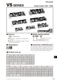
PFE-S SERIES<strong>Single</strong> <strong>Output</strong> <strong>AC</strong>-<strong>DC</strong> <strong>Power</strong> <strong>Module</strong> 2 ■ Features ● PFHC and <strong>DC</strong>/<strong>DC</strong> conversion integrated into a full brickpackage● Wide input voltage range: 85-265V<strong>AC</strong>● High power factor: 0.95, meeting PFHC standard (EN61000- 3-2)● High efficiency: 86% max (PFE300S,500S), 89% max (PFE700S)● Wide operating temperatureBaseplace temperature: -40℃ to +100℃● Stable output voltage type (PFE300S,500S) and high powersemi-regulated type (PFE700S) in the line-up● Parallel operation supported (PFE700S only)● Built-in capacitor: Ceramic type only (high reliability)■ Applications ■ Model naming methodPFE 500 S-12 / □OptionNone: Standard typeT: Mounting stand φ3.3(Non-thread, Through hole)<strong>Output</strong> voltageFunctionS: Simple Function<strong>Output</strong> powerSeries name■ Conformity to RoHS DirectiveThis means that, in conformity with EU Directive2002/95/EC, lead, cadmium, mercury, hexavalentchromium, and specific bromine-based flameretardants, PBB and PBDE, have not been used,except for exempted applications.■ Product Line upPFE-S.(<strong>AC</strong>85-265Vin) <strong>Output</strong> Voltage ・All contents are subject to change without notice.300W 500W 700W<strong>Output</strong> Current Model <strong>Output</strong> Current Model <strong>Output</strong> Current Model12V 25A PFE300S-12 33A PFE500S-12 − −28V 10.8A PFE300S-28 18A PFE500S-28 − − 48V 6.3A PFE300S-48 10.5A PFE500S-48 − −50-57V− − − − 14A PFE700S-48(Semi-regulated)Note) PFE300S/PFE500S are of the stable output voltage type, and they are constant-voltage power supplies as they are. PFE700S is of the semiregulatedtype, and a multiple-output power supply can be configured by connecting other multiple <strong>DC</strong>/<strong>DC</strong> converters on the back of PFE700S.29
PFE500SPFE500S SpecificationsITEMS/UNITSInput(*1) At 100V<strong>AC</strong>/200V<strong>AC</strong> and maximum output power. (Baseplate temperature = +25℃.)(*2) For cases where conformance to various safety specs (UL, CSA, EN) are required,input voltage range will be 100 ~ 240V<strong>AC</strong> (50/60Hz).(*3) Ratings - refer to derating curve on the right.(*4) Heatsink has to be chosen according to instruction manual.(*5) External components are needed for operation. (Refer to basic connection and instruction manual.)(*6) Refer to instruction manual.(*7) Ambient temperature min=-40℃MODEL PFE500S-12 PFE500S-28 PFE500S-48Voltage Range (*2)(*5) V <strong>AC</strong>85 - 265Frequency (*2) Hz 47 - 63<strong>Power</strong> Factor (min) (*1)(*5) 0.95Efficiency (typ) (*1) % 82 / 83 84 / 86Current (*1) A 5.0 / 3.0 6.2 / 3.2Inrush Current (typ) (*1)(*5) A 20 / 40 peakNominal Voltage (*1) V<strong>DC</strong> 12 28 48Maximum Current A 33 18 10.5Maximum <strong>Power</strong> W 396 504Voltage Setting Accuracy % ±2<strong>Output</strong>Maximum Line Regulation mV 48 56 96Maximum Load Regulation mV 48 56 96Maximum Ripple & Noise (*5) mVp-p 120 280 480Voltage Adjustable Range -20% / +20%Over Current ProtectionOver Voltage Protection125% - 145% (Inverter shutdown method)FunctionParallel Operation -Derating Curve105% - 140% (Automatic recovery method)Series Operation (*6) PossibleOperating Temperature (*3)(*7) ℃ -40 to +85 (Baseplate) -40 to +100 (Baseplate)Storage Temperature ℃ -40 to +100Operating Humidity %RH 20 - 95 (No dewdrop)Storage Humidity %RH 10 - 95 (No dewdrop)EnvironmentAt no operating, 10-55Hz (sweep for 1min.)VibrationAmplitude 0.825mm constant (maximum 49.0m/s²) X, Y, Z 1 hour eachShock196.1m/s²Cooling (*4) Conduction cooledInput-BaseplateWithstand VoltageIsolationIsolation ResistanceStandards Safety Standards: 2.5kV<strong>AC</strong>, Input-<strong>Output</strong> : 3.0kV<strong>AC</strong> for 1min.<strong>Output</strong>-Baseplate : 1.5kV<strong>DC</strong> for 1min.<strong>Output</strong> to Baseplate 500V<strong>DC</strong> more than 100MΩ (25℃, 70%RH)Approved by UL60950-1, CSA C22.2 No.60950-1, EN60950-1Weight (typ) g 250MechanicalSize (W x H x D) mm 61 x 12.7 x 116.8 (Refer to outline drawing.)10080Load(%)604020PFE500S-12PFE500S-28,48085-40 -20 0 20 40 60 80 100Baseplate Temperature(℃)・All contents are subject to change without notice.31
PFE300S, 500SOutline Drawing (unit : mm) Basic Connection NOTES:A: Model name, input voltage range, nominaloutput voltage, maximum output current,country of manufacture and safety marking(C-UL-US, BSI & CE marking) are shownhere in accordance with the specifications.B: M3 tapped holes 4 for customer chassismounting (FG).C: <strong>Output</strong> terminal : 2-Φ2D: Input, Intermediate terminal and signal pin:9-Φ1E: Unless otherwise specified dimensionaltolerance : ±0.3 F1 <strong>AC</strong>250V 15A C9 450V 1uF (Film) C15 100V 2.2uF (Ceramic)C1 <strong>AC</strong>250V 1uF (Film) C10 PFE300S:450V 470uF x1 (Elec.) C16 12V: 25V 1000uF (Elec.)C2 4700pF PFE500S:450V 390uF x2 (Elec.) 28V: 50V 470uF (Elec.)C3 4700pF C11 1000pF 48V: 100V 220uF (Elec.)C4 <strong>AC</strong>250V 1uF (Film) C12 0.033uF R1 2W 470kΩC5 <strong>AC</strong>250V 1uF (Film) C13 0.033uF TFR1 10Ω 139℃ (Res., Thermal fuse)C6 1000pF C14 12V: 25V 1000uF (Elec.) L1 6mHC7 1000pF 28V: 50V 470uF (Elec.) L2 6mHC8 450V 1uF (Film) 48V: 100V 220uF (Elec.)Note: Except C10, above components list is for both PFE300S and PFE500S SeriesPlease select component standards, withstand voltage, etc based on the application.32 ・All contents are subject to change without notice.
PFE700SPFE700S SpecificationsITEMS/UNITS MODEL PFE700S-48Voltage Range (*2)(*5) V <strong>AC</strong> 85 - 265Frequency (*2) Hz 47 - 63Input<strong>Power</strong> Factor (min) (*1)(*5) 0.95Efficiency (typ) (*1) % 86 / 89Current (*1) A 8.8 / 4.4Inrush Current (typ) (*1)(*5) A 20 / 40 peakNominal Voltage (*1) V<strong>DC</strong> 51Voltage Regulation Range (*7) V 50 - 57<strong>Output</strong>Maximum Current A 14Maximum <strong>Power</strong> W 714Voltage Setting Accuracy (*1)±1 VMaximum Ripple & Noise (*5)4 Vp-pOver Current Protection105% - 140% (Automatic recovery method)Over Voltage Protection V<strong>DC</strong> 60.0 - 69.6 (Inverter shutdown method)FunctionParallel Operation (*6) PossibleSeries Operation (*6) PossibleOperating Temperature (*3) ℃ -40 to +100 (Baseplate), Ambient temperature min=-40℃Storage Temperature ℃ -40 to +100Operating Humidity %RH 20 - 95 (No dewdrop)Storage Humidity %RH 10 - 95 (No dewdrop)EnvironmentAt no operating, 10-55Hz (sweep for 1min.)VibrationAmplitude 0.825mm constant (maximum 49.0m/s²) X, Y, Z 1 hour eachShock196.1m/s²Cooling (*4) Conduction cooledWithstand VoltageIsolationInput-Baseplate : 2.5kV<strong>AC</strong>, Input-<strong>Output</strong> : 3.0kV<strong>AC</strong> for 1min.<strong>Output</strong>-Baseplate : 1.5kV<strong>DC</strong> for 1min.Isolation Resistance<strong>Output</strong> to baseplate 500V<strong>DC</strong> more than 100MΩ (25℃, 70%RH)Standards Safety StandardsApproved by UL60950-1, CSA C22.2 No.60950-1, EN60950-1Weight (typ) g 250MechanicalSize (W x H x D) mm 61 x 12.7 x 116.8 (Refer to outline drawing.)(*1) At 100V<strong>AC</strong>/200V<strong>AC</strong> and maximum output power. (Baseplate temperature = +25℃.)(*2) For cases where conformance to various safety specs (UL, CSA, EN) are required, input voltage range will be 100 ~ 240V<strong>AC</strong> (50/60Hz).(*3) Ratings - refer to Derating Curve on the right.(*4) Heatsink has to be chosen according to Instruction manual.(*5) External components are needed for operation. (Refer to basic connection and instruction manual.)(*6) Refer to Instruction manual.(*7) For all input voltage, output load and temperature range.Derating Curve10085℃100Tbp:85℃8085%8085%Tbp:100℃Load(%)6040Load(%)604070%20200-40 -20 0 20 40 60 80 100Baseplate Temperature(℃)08580 100 120 140 160 180 200 220 240 260Input Voltage(V<strong>AC</strong>)265・All contents are subject to change without notice.33
PFE700SOutline Drawing Basic ConnectionNOTES:A: Model name, input voltage range, Nominal outputvoltage, Maximum output current, country ofmanufacture and safety marking (C-UL-US, BSI &CE marking) are shown here in accordance withthe specifications.B: M3 tapped holes 4 for customer chassis mounting(FG).C: <strong>Output</strong> terminal : 2-Φ2D: Input, Intermediate terminal and signal pin: 9-Φ1(NC : Make no external connection)E: Unless otherwise specified dimensional tolerance :±0.3F1 <strong>AC</strong>250V 15A C7 1000pF C14 48V: 100V 220uF (Elec.)C1 <strong>AC</strong>250V 1uF (Film) C8 450V 1uF (Film) C15 100V 2.2uF (Ceramic)C2 4700pF C9 450V 1uF (Film) C16 100V 220uF (Elec.)C3 4700pF C10 450V 390uF x2 Parallel (Elec.) R1 2W 470kΩC4 <strong>AC</strong>250V 1uF (Film) C11 1000pF TFR1 10Ω 139℃ (Res., Thermal fuse)C5 <strong>AC</strong>250V 1uF (Film) C12 0.033uF L1 6mHC6 1000pF C13 0.033uF L2 6mHNote: Please select component standards, withstand voltage, etc based on the application.34 ・All contents are subject to change without notice.
PFE300S, 500SBlock Diagram Sequence Time ChartSwitching FrequencyPFHC circuit (fixed) : 100kHz<strong>DC</strong>/<strong>DC</strong> converter (fixed) : 230kHz (primary),460kHz (secondary)Note : This product has no remote ON/OFF function.・All contents are subject to change without notice.35
PFE700SBlock DiagramSwitching FrequencyPFHC circuit (fixed) : 100kHz<strong>DC</strong>/<strong>DC</strong> converter (fixed) : 180kHz (primary), 360kHz (secondary)Sequence Time ChartNote : This product has no remote ON/OFF function.36 ・All contents are subject to change without notice.
PFE300S, 500SPFE300S, 500S Instruction ManualBEFORE USING THE POWER SUPPLY UNITBe sure to read this instruction manual thoroughly before usingthis product. Pay attention to all cautions and warnings beforeusing this product. Incorrect usage could lead to an electricalshock, damage to the unit or a fire hazard.WARNING● Do not make unauthorized changes to power supply unit, otherwiseyou may have electric shock and void your warranty.● Do not touch this unit and the internal components in operationor shortly after shut down. They may have high voltageor high temperature and as the unit dissipates its heat so thesurface of the unit is hot. You may receive electric shock orburn.● When the unit is operating, keep your hands and face awayfrom it; you may be injured by an accident● Do not use unit under unusual condition such as emission ofsmoke or abnormal smell and sound etc. It might cause fireand electric shock. In such case, please contact us; do notrepair by yourself, as it is dangerous for the user.● Do not drop or insert anything into unit. It might cause failureand fire.● Do not operate these units under condensation condition. Itmay cause fire and electric shock.CAUTION● As a component part, compliance with the standard will bebased upon installation in the final application. This productmust be installed in a restricted access location, accessibleto authorized competent personnel only. These <strong>AC</strong> to <strong>DC</strong>converters have reinforced insulation between the input andthe output. The outputs of these products are energy hazards.All models with an output greater than 48V model areconsidered to be non-SELV. As such, the instructions for usemust refer to these energy hazardous outputs and Non-SELVoutputs in that the outputs must not be accessible to theoperator. The installer must also provide protection againstinadvertent contact by a service engineer.● The equipment has been evaluated for use in a Pollution Degree2 environment.● This power supply is primarily designed and manufactured tobe used and enclosed in other equipment.● Confirm connections to input/output terminals and signal terminalsare correct as indicated in the instruction manual.● Attach an HBC external fuse to each module to ensure safetyoperation and compliance to each safety standard approval.The recommended input fuse rating within the instructions isas follows: -15AHBC, 250V fast acting fuse. The breakingcapacity and voltage rating of this fuse may be subject to theend use application.● Input voltage, output current, output power, ambient temperatureand ambient humidity should be used within specifications,otherwise the unit will be damaged.● For application equipment, which requires very high reliability(nuclear related equipment, traffic control equipment, medicalequipment, etc.), please provide fail safety function in theequipment.● Do not use the product in environment with strong electromagneticfield, corrosive gas and conductive substance.● Do not operate and store this unit at an environment wherecondensation occurs. In such case, waterproof treatment isnecessary● Never operate the unit under over current or shorted conditionsfor 30 seconds or more and out of Input Voltage Rangeas specification. Insulation failure, smoking, burning or otherdamage may occur to the unit.● The output voltage of this power supply unit is consideredto be a hazardous energy level. (The voltage is 2V or moreand the electric power is 240VA or more.) Prevention fromdirect contact with output terminal is highly necessary. Whileinstalling or servicing this power supply unit, avoid droppingtools by mistake or direct contact with output terminal. Thismight cause an electric shock. While repairing this powersupply unit, the <strong>AC</strong> input power must be switched off and theinput and output voltage should be level.● To maintain the SELV output for outputs less than 28V<strong>DC</strong>,under fault conditions, the output must be connected to earthin the final application.● The application circuits and their parameter are for referenceonly. Be sure to verify effectiveness of application circuitsand their parameters before finalizing circuit design.● Do not inject abnormal voltage to output terminal and signalterminal from the outside. The injection of reverse voltage orover voltage exceeding nominal output voltage to output terminalsmight cause damage to internal components.● This information in this document is subject to change withoutprior notice. For actual design-in, please refer to the latestpublications of data sheet, etc., for the most up-to-datedate specifications of the unit.● No part of this document may be copied or reproduced in anyform without prior written consent of <strong>TDK</strong>-<strong>Lambda</strong>.Note : CE MARKINGCE Marking when applied to a product covered by this handbookindicates compliance with the low voltage directive (2006/95/EC) in that it complies with EN60950-1.・All contents are subject to change without notice.37
PFE300S, 500S1. Terminal Explanation[Input side terminals]<strong>AC</strong>(L) : Input terminal live line<strong>AC</strong>(N) : Input terminal neutral line[<strong>Output</strong> side terminals]+V : +<strong>Output</strong> terminal-V : -<strong>Output</strong> terminal+BC :-BC :R :+Boosted voltage terminal-Boosted voltage terminalExternal inrush current limiting resistor+S : +Remote sensing terminal-S : -Remote sensing terminalTRIM : <strong>Output</strong> voltage trimming terminalENA : <strong>Power</strong> on signal terminal・Baseplate can be connected to FG through M3 mounting tapped holes.・Consider contact resistance when connecting <strong>AC</strong>(L), <strong>AC</strong>(N), R, +BC, -BC, +V, -V.・Note that +BC and -BC terminals is a primary voltage with high voltage (385V<strong>DC</strong>).Do not connect load from these terminals.2. Explanations on SpecificationsThis manual explains based on “Fig.1-1 Basic Connection”.Please do actual evaluation when changing circuit from Fig.1-1.1 Input Voltage RangeInput voltage range is indicated below. Take care not toapply input voltage which is out of this specified range norshould a <strong>DC</strong> input voltage be applied as this would resultinto power module damage.Input Voltage Range: <strong>Single</strong> Phase 85 to 265V<strong>AC</strong>Line Frequency Range: 47 to 63Hz Fig. 1-1 Basic Connection38 ・All contents are subject to change without notice.
PFE300S, 500SF1: External Input FuseThis power module has no internal fuse. Use external fuseto acquire each safety standard and to further improvesafety. Further, Fast-Blow type fuse must be used per onemodule. Also, in-rush surge current flows during line throwin.Be sure to check I 2 t rating of external switch and externalfuse.Recommended External Fuse: 15ASelect fuse based on rated voltage, rated current andsurge current capability.(1)Voltage Ratings100V<strong>AC</strong> line: <strong>AC</strong>125V200V<strong>AC</strong> line: <strong>AC</strong>250V(2)Current RatingsRated current is determined by the maximum inputcurrent based on operating conditions and can be calculatedby the following formula.lin(max) =PoutVin x Eff x PF(Arms) (Formula 1-1)Iin (max): Maximum Input CurrentPout: Maximum <strong>Output</strong> <strong>Power</strong>Vin: Minimum Input VoltageEff: EfficiencyPF: <strong>Power</strong> FactorFor efficiency and power factor values, refer to separate"Evaluation Data of each product".C1, C4, C5: 1uF (Film Capacitor)Ripple current flows through this capacitor. When selectingcapacitor, be sure to check the allowable maximum ripplecurrent rating of this capacitor. Verify the actual ripplecurrent flowing through this capacitor by doing actual measurement.Recommended Voltage Rating: 250V<strong>AC</strong>Note)Connect C5 as near as possible towards the input terminalsof this power module.L1, L2: 6mHAdd common mode choke coil as EMI/EMS counter-measure.When using multiple modules, connect coil to eachmodule.Note)Depending on the input filter used, noise might increaseor power module might malfunction due to filter resonance.C2, C3: 4,700pF (Ceramic Capacitor)Add ceramic capacitor as EMI/EMS countermeasure. Besure to consider leakage current of your equipment whenadding this capacitor.High withstand voltage are applied across this capacitordepending on the application. Select capacitors with highwithstand voltage rating.C6, C7: 1000pF (Ceramic Capacitor)Add ceramic capacitor as EMI/EMS countermeasure. Besure to consider leakage current of your equipment whenadding this capacitor.High withstand voltage are applied across this capacitorduring withstand voltage test depending on the application.Select capacitors with high withstand voltage rating.Also, connect C6, C7 as close as possible to the terminals.C8, C9: 1uF (Film Capacitor)Ripple current flows through this capacitor. When selectingcapacitor, be sure to check the allowable maximum ripplecurrent rating of this capacitor. Verify the actual ripplecurrent flowing through this capacitor by doing actual measurement.Recommended Voltage Rating : 450V<strong>DC</strong>Note)Select Capacitor with more than 3A (rms) rating. ConnectC8, C9 as near as possible towards the output terminalsof this power module.C10: Electrolytic CapacitorPFE300S: 470μF×1PFE500S: 390μF×2 pcs in parallelRefer to "Selection Method of External Bulk Capacitor forBoost Voltage" below.Allowable External Capacitance at nominal capacitor valueis shown below.Recommended Voltage Rating: 450V<strong>DC</strong>Recommended Total Capacitor: 390uF to 1,200uFNote)1. Do not connect capacitors with more than the abovecapacitance value as this would result into powermodule damage.2. When using module below -20℃ ambient temperature,<strong>AC</strong> ripple of boost voltage, output ripple voltage andstand up characteristics might be affected by ESRcharacteristics of the bulk capacitor.Therefore, be sure to verify characteristics by actualevaluation.C11: 1000pF (Ceramic Capacitor)Add ceramic capacitor as EMI/EMS countermeasure.High withstand voltage are applied across this capacitorduring withstand voltage test depending on the application.Select capacitors with high withstand voltage rating.Also, connect C11 as close as possible to the terminals.C12, C13: 0.033uFConnect ceramic or film capacitor as EMI/EMS countermeasureand to reduce spike noise.Note)High Voltage is applied across this capacitor duringwithstand voltage test depending on the application.Connect C12, C13 as near as possible towards the outputterminals of this power module.R1: 470kΩConnect bleeder resistor across <strong>AC</strong>(L) and <strong>AC</strong>(N) terminals.・All contents are subject to change without notice.39
PFE300S, 500SC14: Refer to Table 1-1To reduce output ripple noise voltage, connect electrolyticcapacitors across +V and -V.Note)Connect C14 as near as possible to the +V and -V outputterminals of this power module.Vout12V28V48VC1425V 1,000uF50V 470uF100V 220uFTable 1-1 C14 : Recommended external capacitanceC15: 2.2uFConnect chip ceramic capacitor within 50mm from theoutput terminals +V and -V of the power module to reduceoutput spike noise.Also, note that output spike voltage may vary depending onthe wiring pattern of the printed circuit board.C16 : Refer to Table 1-2Connect C16 within 50mm from the output terminals +Vand -V of the power module to stabilize operation.Note that the output ripple and line turn off characteristicsof the power module might be affected by the ESR andESL of the electrolytic capacitor.Also, note that output ripple voltage may vary dependingon the wiring pattern of the printed circuit board.Sudden change in output voltage due to sudden loadchange or sudden input voltage change can be reduced byincreasing external output capacitor value.Vout12V28V48VC1625V 1,000uF50V 470uF100V 220uFTable 1-2 C16 : Recommended external capacitanceNote)1. Use low-impedance electrolytic capacitors with excellenttemperature characteristics.(Nihon Chemi-con LXY Series or equivalent)(Nichicon PM Series or equivalent)2. For module operation at ambient temperature -20℃ orless, output ripple voltage might be affected by ESRcharacteristics of the electrolytic capacitors. Increasethe capacitor values shown in Table 1-1 and 1-2 accordingto the table below.Vout12V28V48VC14,C1625V 1,000uF x 2parallel50V 470uF x 2parallel100V 220uF x 2parallelTable 1-3 C14, C16 : Recommended externalcapacitance(Ambient Temperature < -20 deg C)3. Take note of the maximum allowable ripple current ofthe electrolytic capacitor used. Especially, for suddenload current changes, verify actual ripple current andmake sure that allowable maximum ripple current isnot be exceeded.● Selection Method of External Bulk Capacitor forBoost VoltageBoost voltage bulk capacitor is determined by boost voltageripple voltage, ripple current and hold-up time.Select capacitor value such that boost voltage ripple voltagedoes not exceed 15Vp-p.Note)When ambient temperature is -20℃ or less,Boost voltage might increase due to ESR characteristics.Therefore, verify above characteristics by actual evaluation.For output hold-up time, refer to separate document "PFE300S Series Evaluation Data" or "PFE500S Series EvaluationData" and use appropriate capacitor up to 1,200uFmaximum. (It is recommended that verification should bedone through actual evaluation).For allowable ripple current value, refer to Fig. 1-2 and selecta capacitor with higher ripple current rating. Fig. 1-2 Allowable ripple current valueTFR1 : 10 to 100ΩBy connecting thermal fuse resistor across R and +BCterminals as shown in Fig.1-1, in-rush current during linethrow-in can be suppressed. Failures due to in-rush currentsuch as melting of external fuse, welding of relay or switchconnecting joints or shutdown of No-Fuse Breakers (NFB)can occur. Therefore, be sure to connect this external thermalfuse resistor.Note that this module will not operate without this externalresistor.● Selection Method of External Resistor(1)Calculating Resistance Value for TFR1Resistance can be calculated by the formula below.R=Vinlrush(Ω) (Formula 1-2)R: Resistance Value for External TFR1Vin: Input Voltage converted to <strong>DC</strong> value=Input Votlage (rms) ×√ ̄2Irush: Input surge current value(2)Required Surge Current RatingSufficient surge current withstand capability is requiredfor external TFR1.Required Surge Current Rating can be selected by I 2 t.(Current squared multiplied by time).40 ・All contents are subject to change without notice.
PFE300S, 500Sl 2 t= Co x Vin2 (A 2 s) (Formula 1-3)2 x RI 2 t: Current-squared multiplied by timeCo: Booster Voltage Bulk CapacitanceVin: Input Voltage converted to <strong>DC</strong> value= Input Voltage (rms) x √ ̄2R: Resistance Value for External TFR12 <strong>Output</strong> Voltage Adjustment Range<strong>Output</strong> Voltage can be adjusted within the range below byconnecting fixed and variable resistors. However, take carenot to exceed the output voltage range shown below becauseOVP function will activate.<strong>Output</strong> Voltage Adjustment Range :±20% of the typical voltage ratingWhen increasing output voltage, reduce output current soas not to exceed maximum output power.Even if the output voltage is adjusted using external circuitshown in Fig.2-1, remote sensing can be done. For detailson remote sensing function, refer to "9. Remote Sensing".<strong>Output</strong> Voltage Adjustment using Fixed and VariableResistorsExternal resistor (R1) and variable resistor (VR) values, aswell as, circuit connection is shown below.For this case, remote programming of the output voltagecan be done through the remote programming resistor VR.Be sure to connect the remote programming resistor between+S and +V terminals.12V 28V 48VR1 10k 47k 100kVR 10k 20k 30kunit: [Ω]External Resistor: Tolerance ±5% or lessVariable Resistor: Total Tolerance ±20% or lessEnd Resistance 1% or lessTable 2-1 External Resistor and Variable Resistor Value(For ±20% <strong>Output</strong> Adjustment)Capacitor: Refer to Table 1-2) must be connected within50mm from the output terminals. Then, connect coaxialcable with JEITA attachment across the ceramic capacitorelectrodes. Use 100MHz bandwidth oscilloscope or equivalent.Also, note that output ripple voltage and output spike noisemay vary depending on the wiring pattern of the printedcircuit board.In general, output ripple voltage and output spike noise canbe reduced by increasing external capacitor value.Fig. 3-1 <strong>Output</strong> Ripple Voltage (including Spike Noise)Measurement Method4 Maximum Line RegulationMaximum line regulation is defined as the maximum outputvoltage change when input voltage is gradually changed(Steady-State) within specification range.5 Maximum Load RegulationMaximum load regulation is defined as the maximum outputvoltage change when output load current is graduallychanged (Steady-State) within specification range.When using power module in dynamic load mode, audiblesound could be heard from the power module or large outputvoltage change can occur. Make prior evaluation thoroughlybefore using this power module.6 Over Current Protection (OCP)This module is equipped with OCP function.<strong>Output</strong> will automatically recover when short circuit oroverload condition is removed. OCP value is fixed and cannotbe adjusted externally.Note that continuous short circuit or overload conditionmight result in power module damage.Fig. 2-1 External Resistor Connection Example3 Maximum Ripple and NoiseThis value is measured according to the description belowin accordance with JEITA-9131A (Section 7.12 and Section7.13).In the basic connection shown in Fig.1-1, additionalconnection shown in Fig.3-1 is done for measurement.Capacitor (Ceramic Capacitor: 2.2μF and Electrolytic7 Over Voltage Protection (OVP)This module is equipped with OVP function. This value isset between 125% to 145% of nominal output voltage.When the OVP function activates, first cut off input lineand verify that boost voltage has dropped down to 20V orless. Then, recover output by recycling input line.OVP value is fixed and cannot be set externally.・All contents are subject to change without notice.41
PFE300S, 500S8 Over Temperature Protection (OTP)This module is equipped with OTP function. This functionwill activate and shutdown the output when ambienttemperature or internal temperature abnormally rises. OTPactivates at following baseplate temperature.PFE300S-12, 28, 48: 105 to 130℃PFE500S-12: 90 to 115℃PFE500S-28, 48: 105 to 130℃When OTP function operates, output can be recoveredby cooling down the baseplate sufficiently and letting theboost voltage drop down to 20V or less before recyclingthe input line.9 Remote Sensing (+S, -S Terminals)This module has remote sensing terminals to compensatefor voltage line drop from the output terminals to the outputload. When remote sensing is not required (local sensing)short +S to +V and -S to -V terminals respectively.Note that line drop (voltage drop due to wiring ) compensationvoltage range must be such that the output voltageis within the output voltage adjustment range and that thevoltage between -V and -S must be within 2V.Consider power loss due to line drop and use power modulewithin the maximum allowable output power. Reducethe effect of noise to the remote sensing line by using ashield line, a twist pair, or a parallel pattern, etc.Fig. 10-1 Series Operation for High <strong>Output</strong> VoltageApplicationsFig. 10-2 ±<strong>Output</strong> Series Applications <strong>Power</strong> ON Signal (ENA Terminal)This signal is located at the secondary side (output side)Fig. 9-1 Remote Sensing is usedand is an open collector output.(Maximum sink current is 10mA and maximum applied voltageis 75V.)Return line for ENA terminal is the -V terminal.When output voltage goes over a specified voltage level atstart up, <strong>Power</strong> ON signal is "Low level".<strong>Output</strong> voltage threshold level is as follows.PFE300S or PFE500-12:9V (TYP)PFE300S or PFE500-28:21V(TYP)PFE300S or PFE500-48:37V(TYP)On the other hand, output voltage threshold level for <strong>Power</strong>ON signal to turn high level at shutdown varies accordingto output condition. Therefore, be sure to do actual verification. Fig. 9-2 Remote Sensing is not used (Local Sensing) Series OperationSeries operation is possible for PFE300S, 500S Series.Connections shown in Fig.10-1 and Fig.10-2 are possible. Operating Ambient Temperature RangeThese products can be used in any orientation but be sureto consider enough airflow to avoid heat accumulationaround the module. Consider surrounding components layoutand set the PCB mounting direction such that air canflow through the heatsink by forced or convection cooling.This product can operate at actual mounting conditionwhen baseplate temperature is maintained at or below thefollowing baseplate temperature:PFE300S-12, 28, 48: 100℃PFE500S-12: 85℃PFE500S-28, 48: 100℃42 ・All contents are subject to change without notice.
PFE300S, 500SVerify baseplate temperature at worst case operating conditionat the measuring point shown in Fig. 12-1.For Thermal Design details, refer to Application Notes"Thermal Design" section.Fig. 12-1 Baseplate Measuring PointBaseplate temperature range is limited according to Fig.12-2. Fig. 12-2 Derating CurveTo further improve the reliability, it is recommended to usethis module with baseplate temperature derating.input and output for a duration of 1 minute. When doingthis test during incoming inspection, set the current limit oftest equipment to 20mA.This module is designed to withstand applied voltage1.5kV<strong>DC</strong> between output and baseplate for 1 minute.When doing this test during incoming inspection, be sureto apply <strong>DC</strong> voltage only. Avoid applying <strong>AC</strong> voltage duringthis test because this will damage the module.Refrain from injecting high test voltage suddenly. Be sureto gradually increase the applied withstand voltage duringtesting and gradually reduce the voltage after the test.Especially, when using timer switch of the test equipment,impulse voltage which is higher than the applied set voltage,is generated when the timer switch is cut off. Thiscauses damage to the power module. Connect each terminalaccording to the circuit diagram shown below.For basic connection shown in Fig.1-1, do the same terminalconnections. 2.5kV<strong>AC</strong> 1 minute (20mA)Fig. 17-1 Input to Baseplate Withstand Voltage TestMethod Operating Ambient HumidityNote that dewdrop might cause power module abnormaloperation or damage. Storage Ambient TemperatureNote that rapid temperature change causes dewdrop. causingharmful effect on soldering condition of the terminalpins. Storage Ambient HumidityStorage under high temperature and high humidity causesrust on terminal pins that causes deterioration of solderingconditions. Take enough caution when storing this module. 3kV<strong>AC</strong> 1 minute (20mA)Fig.17-2 Input to <strong>Output</strong> Withstand Voltage Test Method Cooling MethodFor details of thermal design, refer to Application Notes"Thermal Design" section. Withstand VoltageThis module is designed to withstand applied voltage2.5kV<strong>AC</strong> between input and baseplate, 3kV<strong>AC</strong> between1.5kV<strong>DC</strong> 1 minuteFig.17-3 <strong>Output</strong> to Baseplate Withstand Voltage TestMethod・All contents are subject to change without notice.43
PFE300S, 500S Insulation ResistanceUse <strong>DC</strong> Insulation Resistance test equipment (MAX.500V)between output and baseplate.Insulation Resistance must be 100MΩ or more at 500V<strong>DC</strong>.Take caution that some types of test equipment generatehigh pulse voltage when switching applied voltage. Aftertest, discharge this module using resistor, etc. Recommended Soldering ConditionRecommended soldering temperature is as follows.(1)Soldering Dip : 260℃, within 10 secondsPreheat : 130℃, within 60 seconds(2)Soldering iron : 350℃, within 3 seconds 100MΩ or more at 500V<strong>DC</strong>Fig. 18-1 Insulation Resistance Test Method3. Before Concluding <strong>Power</strong> <strong>Module</strong> DamageVerify following items before concluding power moduledamage.1)No output voltage● Is specified input voltage applied?● During output voltage adjustment, is the fixed resistoror variable resistor setting correct?● Is there no abnormality with the output load?● Is the actual baseplate temperature within the specifiedoperating temperature of this module?2)<strong>Output</strong> voltage is high● Are the remote sensing terminals (+S, -S) correctlyconnected?● Is the measurement done at the sensing points?● During output voltage adjustment, is the fixed resistoror variable resistor setting correct?4)Load regulation or line regulation is large● Is specified input voltage applied?● Are the input or output terminals firmly connected?● Is the measurement done at the sensing points?● Are the input and output wires too thin?5)Large output ripple● Is the measurement done according to methodsdescribed Application Notes or is it an equivalentmethod?3)<strong>Output</strong> voltage is low● Is specified input voltage applied?● Are the remote sensing terminals (+S, -S) correctlyconnected?● Is the measurement done at the sensing points?● During output voltage adjustment, is the fixed resistoror variable resistor setting correct?● Is there no abnormality with the output load?44 ・All contents are subject to change without notice.
PFE700SPFE700S Instruction ManualBEFORE USING THE POWER SUPPLY UNITBe sure to read this instruction manual thoroughly before usingthis product. Pay attention to all cautions and warnings beforeusing this product. Incorrect usage could lead to an electricshock, damage to the unit or a fire hazard.WARNING● Do not make unauthorized changes to power supply unit, otherwiseyou may have electric shock and void your warranty.● Do not touch this unit and the internal components in operationor shortly after shut down. They may have high voltageor high temperature and as the unit dissipates its heat so thesurface of the unit is hot. You may receive electric shock orburn.● When the unit is operating, keep your hands and face awayfrom it; you may be injured by an accident.● Do not use unit under unusual condition such as emission ofsmoke or abnormal smell and sound etc. It might cause fireand electric shock. In such case, please contact us; do notrepair by yourself, as it is dangerous for the user.● Do not drop or insert anything into unit. It might cause failureand fire.● Do not operate these units under condensation condition. Itmay cause fire and electric shock.CAUTION● As a component part, compliance with the standard will bebased upon installation in the final application. This productmust be installed in a restricted access location, accessibleto authorized competent personnel only. These <strong>AC</strong> to<strong>DC</strong> converters have reinforced insulation between the inputand the output. The outputs of these products are energyhazards. This model is considered to be non-SELV. As such,the instructions for use must refer to these energy hazardousoutputs and Non-SELV outputs in that the outputs must notbe accessible to the operator. The installer must also provideprotection against inadvertent contact by a service engineer.● The equipment has been evaluated for use in a Pollution Degree2 environment.● This power supply is primarily designed and manufactured tobe used and enclosed in other equipment.● Confirm connections to input/output terminals and signal terminalsare correct as indicated in the instruction manual.● Attach an HBC external fuse to each module to ensure safetyoperation and compliance to each safety standard approval.The recommended input fuse rating within the instructions isas follows: -15AHBC, 250V fast acting fuse. The breakingcapacity and voltage rating of this fuse may be subject to theend use application.● Input voltage, output current, output power, ambient temperatureand ambient humidity should be used within specifications,otherwise the unit will be damaged.● For application equipment, which requires very high reliability(nuclear related equipment, traffic control equipment, medicalequipment, etc.), please provide fail safety function in theequipment.● Do not use the product in environment with strong electromagneticfield, corrosive gas and conductive substance.● Do not operate and store this unit at an environment wherecondensation occurs. In such case, waterproof treatment isnecessary.● Never operate the unit under over current or shorted conditionsfor 30 seconds or more and out of input voltage rangeas specification. Insulation failure, smoking, burning or otherdamage may occur to the unit.● The output voltage of this power supply unit is considered tobe a hazardous energy level. (The voltage is 2V or more andthe electric power is 240VA or more.) Prevention from directcontact with output terminal is highly necessary. While installingor servicing this power supply unit, avoid dropping toolsby mistake or direct contact with output terminal. This mightcause an electric shock. While repairing this power supplyunit, the <strong>AC</strong> input power must be switched off and the inputand output voltage should be level.● To maintain the SELV output for outputs less than 28V<strong>DC</strong>,under fault conditions, the output must be connected to earthin the final application.● The application circuits and their parameter are for referenceonly. Be sure to verify effectiveness of application circuitsand their parameters before finalizing circuit design.● Do not inject abnormal voltage to output terminal and signalterminal from the outside. The injection of reverse voltage orover voltage exceeding nominal output voltage to output terminalsmight cause damage to internal components.● This information in this document is subject to change withoutprior notice. For actual design-in, please refer to the latestpublications of data sheet, etc., for the most up-to-datespecifications of the unit.● No part of this document may be copied or reproduced in anyform without prior written consent of <strong>TDK</strong>-<strong>Lambda</strong>.Note:CE MARKINGCE Marking when applied to a product covered by this handbookindicates compliance with the low voltage directive (2006/95/EC) in that it complies with EN60950-1.・All contents are subject to change without notice.45
PFE700S1. Terminal Explanation<strong>AC</strong>(N) –V<strong>AC</strong>(L)Name Plate+V–VM+VMNCENAR+BC–BC[Input side terminals][<strong>Output</strong> side terminals]<strong>AC</strong>(L): Input terminal live line<strong>AC</strong>(N): Input terminal neutral line+V :-V :+<strong>Output</strong> terminal-<strong>Output</strong> terminal+BC : +Boost voltage terminal-BC : -Boost voltage terminalR : External inrush current limiting resistor+VM : +V<strong>Output</strong> monitor terminal−VM : −V<strong>Output</strong> monitor terminalNC : Make no external connectionENA : <strong>Power</strong> on signal terminal・ Baseplate can be connected to FG through M3 mounting tapped holes.・ Consider contact resistance when connecting <strong>AC</strong>(L), <strong>AC</strong>(N), R, +BC, −BC, +V, −V.・ Note that +BC and −BC terminals are primary voltage with high voltage (385V<strong>DC</strong>).Do not connect load from these terminals.・ Do not make external connection to NC terminal.1 Input Voltage Range2. Explanations on SpecificationsThis manual explains based on "Fig. 1-1 Basic Connection." Please do actual evaluation when changing circuit from Fig.1-1.Input voltage range is indicated below. Take care not toapply input voltage which is out of this specified range norshould a <strong>DC</strong> input voltage be applied as this would resultinto power module damage.Input Voltage Range: <strong>Single</strong> Phase 85 to 265V<strong>AC</strong>Line Frequency Range : 47 to 63Hz Fig. 1-1 Basic Connection46 ・All contents are subject to change without notice.
PFE700SF1: External Input FuseThis power module has no internal fuse. Use external fuseto acquire each safety standard and to further improvesafety. Further, Fast-Blow type fuse must be used per onemodule. Also, in-rush surge current flows during line throwin.Be sure to check I 2 t rating of external switch and externalfuse.Recommended External Fuse:15ASelect fuse based on rated voltage, rated current andsurge current capability.(1)Voltage Ratings100V<strong>AC</strong> line:<strong>AC</strong>125V200V<strong>AC</strong> line:<strong>AC</strong>250V(2)Current RatingsRated current is determined by the maximum inputcurrent based on operating conditions and can be calculatedby the following formula.lin(max)=Pout(Arms)(Formula 1-1)Vin×Eff×PFIin(max):Maximum Input CurrentPout:Vin:Eff:PF:Maximum <strong>Output</strong> <strong>Power</strong>Minimum Input VoltageEfficiency<strong>Power</strong> FactorFor efficiency and power factor values, refer to separatedocument "PFE700S Series Evaluation Data".C1, C4, C5:1μF(Film Capacitor)Ripple current flows through this capacitor. When selectingcapacitor, be sure to check the allowable maximum ripplecurrent rating of this capacitor. Verify the actual ripplecurrent flowing through this capacitor by doing actual measurement.Recommended Voltage Rating: 250V<strong>AC</strong>Note)Connect C5 as near as possible towards the input terminalsof this power module.L1, L2:6mHAdd common mode choke coil as EMI/EMS counter-measure.When using multiple modules, connect coil to eachmodule.Note)Depending on the input filter used, noise might increaseor power module might malfunction due to filter resonance.C2, C3: 4,700pF(Ceramic Capacitor)Add ceramic capacitor as EMI/EMS countermeasure. Besure to consider leakage current of your equipment whenadding this capacitor.High withstand voltage are applied across this capacitordepending on the application. Select capacitors with highwithstand voltage rating.R1:470kΩConnect bleeder resistor across <strong>AC</strong>(L) and <strong>AC</strong>(N) terminals.C6, C7: 1000pF(Ceramic Capacitor)Add ceramic capacitor as EMI/EMS countermeasure. Besure to consider leakage current of your equipment whenadding this capacitor.High withstand voltage are applied across this capacitorduring withstand voltage test depending on the application.Select capacitors with high withstand voltage rating.Also, connect C6, C7 as close as possible to the terminals.C8, C9:1μF(Film Capacitor)Ripple current flows through this capacitor. When selectingcapacitor, be sure to check the allowable maximum ripplecurrent rating of this capacitor. Verify the actual ripplecurrent flowing through this capacitor by doing actual measurement.Recommended Voltage Rating:450V<strong>DC</strong>Note)Select Capacitor with more than 3A (rms) rating. ConnectC8, C9 as near as possible towards the output terminalsof this power module.C10:780μF(390μF×2 pcs. in parallel)(Electrolytic Capacitor)Refer to "Selection Method of External Bulk Capacitor forBoost Voltage" below.Allowable external capacitance at nominal capacitor valueis shown below.Recommended Voltage Rating: 450V<strong>DC</strong>Recommended Total Capacitor: 390uF to 1,200uFNote)1. Do not connect capacitors with more than the abovecapacitance value as this would result into powermodule damage.2. When using module below -20 deg C ambient temperature,<strong>AC</strong> ripple of boost voltage, output ripple voltageand start up characteristics might be affected by ESRcharacteristics of the bulk capacitors. Therefore, besure to verify characteristics by actual evaluation.C11: 1000pF(Ceramic Capacitor)Add ceramic capacitor as EMI/EMS countermeasure.High withstand voltage are applied across this capacitorduring withstand voltage test depending on the application.Select capacitors with high withstand voltage rating.Also, connect C11 as close as possible to the terminals.C12, C13:0.033μFConnect ceramic or film capacitor as EMI/EMS countermeasureand to reduce spike noise.Note)High voltage is applied across this capacitor during withstandvoltage test depending on the application.Connect C12, C13 as near as possible towards the outputterminals of this power module.C14:220μFTo reduce output ripple noise voltage, connect electrolyticcapacitors across +V and −V.Note)Connect C14 as near as possible to the +V and −Voutput terminals of this power module.・All contents are subject to change without notice.47
PFE700SRecommended Voltage Rating:100V<strong>DC</strong>C15:2.2μFConnect chip ceramic capacitor within 50mm from the outputterminals +V and −V of the power module to reduceoutput spike noise.Also, note that output spike voltage may vary depending onthe wiring pattern of the printed circuit board.C16:220μFConnect C13 within 50mm from the output terminals +Vand −V of the power module to stabilize operation.Note that the output ripple and line turn off characteristicsof the power module might be affected by the ESR andESL of the electrolytic capacitor.Also, note that output ripple voltage may vary dependingon the wiring pattern of the printed circuit board.Sudden change in output voltage due to sudden loadchange or sudden input voltage change can be reduced byincreasing external output capacitor value.Recommended Voltage Rating:100V<strong>DC</strong>Note)1. Use low-impedance electrolytic capacitors with excellenttemperature characteristics.(Nichicon PM Series or equivalent)2. For module operation at ambient temperature −20deg C or less, output ripple voltage might be affectedby ESR characteristics of the electrolytic capacitors.Increase the capacitor values shown below.C14, C16: 100V 220μF x 2 parallel(Ambient Temperature
PFE700SFig. 2-1 <strong>Output</strong> Ripple Voltage (including Spike Noise)Measurement Method3 Maximum Line RegulationMaximum line regulation is defined as the maximum outputvoltage change when input voltage is gradually changed(steady-state) within specification range.8 Parallel OperationCurrent share parallel operation is possible for PFE700SSeries by connecting the output terminal of each powermodule. Verify the allowable maximum total output currentby actual evaluation such that maximum output current ratingof each module is not exceeded.Consult us for details when using PFE700S Series at paralleloperation.9 Series OperationSeries operation is possible for PFE700S Series.Connections shown in Fig.9-1 and Fig.9-2 are possible.4 Maximum Load RegulationMaximum load regulation is defined as the maximum outputvoltage change when output load current is graduallychanged (steady-state) within specification range.When using power module in dynamic load mode, audiblesound could be heard from the power module or large outputvoltage change can occur. Make prior evaluation thoroughlybefore using this power module.5 Over Current Protection (OCP)This module is equipped with OCP function.<strong>Output</strong> will automatically recover when short circuit oroverload condition is removed. OCP value is fixed and cannotbe adjusted externally.Note that continuous short circuit or overload conditionmight result in power module damage.6 Over Voltage Protection (OVP)This module is equipped with OVP function. This value isset between 60.0V to 69.6V.When the OVP function activates, first cut off input lineand verify that boost voltage has dropped down to 20V orless. Then, recover output by recycling input line.OVP value is fixed and cannot be set externally.7 Over Temperature Protection (OTP)This module is equipped with OTP function. This functionwill activate and shut down the output when ambienttemperature or internal temperature abnormally rises. OTPactivates at following baseplate temperature.OTP operating temperature:105 to 130 deg CWhen OTP function operates, output can be recoveredby cooling down the baseplate sufficiently and letting theboost voltage drop down to 20V or less before recyclingthe input line.Fig. 9-1 Series Operation for High <strong>Output</strong> Voltage ApplicationsFig. 9-2 +/−<strong>Output</strong> Series Applications <strong>Power</strong> ON Signal (ENA Terminal)This signal is located at the secondary side (output side)and is an open collector output.(Maximum sink current is 10mA and maximum applied voltageis 75V.)When output voltage goes over 46V(TYP) at start up, <strong>Power</strong>ON signal is "Low Level".On the other hand, output voltage threshold level for <strong>Power</strong>ON signal to turn "High Level" at shutdown varies accordingto output condition.Therefore, be sure to do actual verification. Operating Ambient Temperature RangeThese products can be used in any orientation but be sureto consider enough airflow to avoid heat accumulationaround the module. Consider surrounding components layoutand set the PCB mounting direction such that air canflow through the heatsink by forced or convection cooling.This product can operate at actual mounting conditionwhen baseplate temperature is maintained at or below the100 deg C.Verify baseplate temperature at worst case operating conditionat the measuring point shown in Fig.11-1.For Thermal Design details, refer to Application Notes"Thermal Design" section.・All contents are subject to change without notice.49
PFE700SFig.11-1 Baseplate Measuring PointBaseplate temperature range is limited according to Fig.11-2. Fig. 11-2 Derating CurveTo further improve the reliability, it is recommended to usethis module with baseplate temperature derating.to apply <strong>DC</strong> voltage only. Avoid applying <strong>AC</strong> voltage duringthis test because this will damage the module.Refrain from injecting high test voltage suddenly. Be sureto gradually increase the applied withstand voltage duringtesting and gradually reduce the voltage after the test.Especially, when using timer switch of the test equipment,impulse voltage which is higher than the applied set voltage,is generated when the timer switch is cut off. Thiscauses damage to the power module. Connect each terminalaccording to the circuit diagram shown below.For basic connection shown in Fig.1-1, do the same terminalconnections.Withstand Voltage Tester 2.5kV<strong>AC</strong> 1 minute (20mA)Fig. 16-1 Input to Baseplate Withstand Voltage Test Method Operating Ambient HumidityNote that dewdrop might cause power module abnormaloperation or damage. Storage Ambient TemperatureNote that rapid temperature change causes dewdrop causingharmful effect on soldering condition of the terminalpins. Storage Ambient HumidityStorage under high temperature and high humidity causesrust on terminal pins that causes deterioration of solderingconditions. Take enough caution when storing this module. Cooling MethodFor details of thermal design, refer to Application Notes"Thermal Design" section.3kV<strong>AC</strong> 1 minute (20mA)Fig.16-2 Input to <strong>Output</strong> Withstand Voltage Test Method 1.5kV<strong>DC</strong> 1 minuteFig.16-3 <strong>Output</strong> to Baseplate Withstand Voltage Test Method Withstand VoltageThis module is designed to withstand applied voltage2.5kV<strong>AC</strong> between input and baseplate, 3kV<strong>AC</strong> betweeninput and output for a duration of 1 minute. When doingthis test during incoming inspection, set the current limit oftest equipment to 20mA.This module is designed to withstand applied voltage1.5kV<strong>DC</strong> between output and baseplate for 1 minute.When doing this test during incoming inspection, be sure50 ・All contents are subject to change without notice.
PFE700S Insulation ResistanceUse <strong>DC</strong> Insulation Resistance test equipment (MAX.500V)between output and baseplate.Insulation Resistance must be 100Mohm or more at500V<strong>DC</strong>. Take caution that some types of test equipmentgenerate high pulse voltage when switching applied voltage.After test, discharge this module using resistor, etc. Recommended Soldering ConditionRecommended soldering temperature is as follows.(1)Soldering Dip : 260℃, within 10 secondsPreheat : 130℃, within 60 seconds(2)Soldering iron : 350℃, within 3 seconds 100M ohm or more at 500V<strong>DC</strong>Fig. 17-1 Insulation Resistance Test Method3. Before Concluding <strong>Power</strong> <strong>Module</strong> DamageVerify following items before concluding power moduledamage.1)No output voltage● Is specified input voltage applied?● Is there no abnormality with the output load?● Is the actual baseplate temperature within the specifiedoperating temperature of this module?2)<strong>Output</strong> voltage is low● Is specified input voltage applied?● Is there no abnormality with the output load?3)Load regulation or line regulation is large● Is specified input voltage applied?● Are the input or output terminals firmly connected?● Are the input and output wires too thin?4)Large output ripple● Is the measurement done according to methodsdescribed Application Notes or is it an equivalentmethod?・All contents are subject to change without notice.51
WARNING● Do not modify, disassemble, or open this product. Failure to do so can cause electric shock hazard.<strong>TDK</strong>-<strong>Lambda</strong> cannot be held responsible for damage caused by modifications to this product.● Internal voltage can be retained inside the product. Do not touch any parts inside the product becausethere can be high-voltage and high-temperature parts even when the electric current is notapplied. This can cause an electric shock hazard or burn injury.● There can be high-voltage and high-temperature parts even in products without a cover. Do nottouch them. Touching them can cause an electric shock hazard or burn injury.● While electric current is being applied, keep your hands and face away from it. This may cause injuryor an unexpected accident.CAUTION● Be sure to read the catalogue and instruction manual before using this product. For strictly accurateinformation, request the specifications of the delivered product to check the information.Incorrect usage could lead to an electric shock, damage to the product or a fire hazard.● If there are differences between the specific information given for your product and this document,the specific information given for your product has priority.● Use this product within the specified input voltage, output power, output voltage, output current,and range of ambient temperature/ambient humidity. Using this product in conditions beyond thespecification limits can shorten the lifetime of the product, or can cause, damage to the product,electric shock, or a fire hazard.Also, measure the temperature inside the device to check that there are no problems.● Check the direction the product should face and the conditions for ventilation in the specificationsof the delivered product, and use the product in the correct manner.● Disconnect the power input before connecting inputs and outputs.● If an internal fuse becomes burned out, do not use the unit by replacing the fuse. This can causetrouble inside the unit. Be sure to request us to repair the unit.● Insert fuses in the input circuit for products in which protection circuits (elements, fuses, etc.) arenot installed, to prevent smoking or burning. Also for products with protection circuits installedinside, an appropriate use of protection circuits is recommended as there is possibility that the internalprotection circuit may not operate depending on the usage conditions.● Use only the fuses specified or recommended by <strong>TDK</strong>-<strong>Lambda</strong> for external fuses.● This product is designed and manufactured as a component part to be installed in electronic devices.Attach the warning label to the unit and insert the notes in the instruction manual.● Malfunction and failure may be caused if this product is used in a strong electromagnetic field.● Failure may be caused in the power supply unit due to corrosion if used in environments with corrosivegas (hydrogen sulfide, sulfur dioxide, etc.).● Malfunction and failure may be caused if this product is used in environments with conductive substancesor dust.● Be sure to take protective measures against the surge voltage caused by lightning, etc. Damageto the unit may be caused due to irregular voltage.● Connect the frame ground terminal of the power supply unit to the earth terminal of the device, forsafety and to reduce noise. If grounding is not made, it may cause an electric shock hazard.● It is necessary to exchange consumable parts (built-in fan, electrolytic capacitor) periodically. Setan appropriate overhaul interval period for the performance of maintenance. There may be somecases where overhaul maintenance cannot be conducted due to unavailability of parts due to productiondiscontinuation.● This product might fail accidentally or through unexpected conditions. When using this productwith application devices, in which an extremely high reliability is required (Nuclear-related devices,traffic control devices, medical devices, etc.), be sure to ensure that the fail-safe function is effectivein the devices.* As for EMI or immunity, they are measured in the <strong>TDK</strong>-<strong>Lambda</strong> standard conditions. It is not guaranteedthat this product meets industry standards or regulations when being used in differentconditions of mounting and wiring. Assess and evaluate values on the actual device before use.* To export this product, follow the necessary procedures of application for the export license by thegovernment of Japan, etc., complying with the regulations of the Foreign Exchange and ForeignTrade Control Law.* The information in this catalogue is subject to change without prior notice.・All specifications are subject to change without notice.53
<strong>TDK</strong>-<strong>Lambda</strong> CorporationHEAD OFFICE Denpa Bldg. 1-11-15 Higashi-Gotanda,Shinagawa-ku, Tokyo 141-0022, JAPANTel: +81-03-3447-4411 Fax: +81-03-3447-7784http://www.tdk-lambda.com/<strong>TDK</strong>-<strong>Lambda</strong> Sales NetworkASI<strong>AC</strong>HINAWuxi <strong>TDK</strong>-<strong>Lambda</strong> Electronics Co., Ltd. (Shanghai Office)Tel: +86-21-6485-0777Fax: +86-21-6485-0666Wuxi <strong>TDK</strong>-<strong>Lambda</strong> Electronics Co., Ltd. (Shenzhen Office)Tel: +86-755-83588261Fax: +86-755-83588260Wuxi <strong>TDK</strong>-<strong>Lambda</strong> Electronics Co., Ltd. (Beijing Office)Tel: +86-10-6310-4872Fax: +86-10-6310-4874<strong>TDK</strong>-<strong>Lambda</strong> Corporation (Hong Kong Office)Tel: +852-2420-6693Fax: +852-2420-3362Wuxi <strong>TDK</strong>-<strong>Lambda</strong> Electronics Co., Ltd. (Chengdu Office)Tel: +86-28-85311929Fax: +86-28-85311150Wuxi <strong>TDK</strong>-<strong>Lambda</strong> Electronics Co., LtdTel: +86-510-85281029Fax: +86-510-85282585INDIA<strong>TDK</strong>-<strong>Lambda</strong> India (Bangalore Office)Tel: +91-80-43550500Fax: +91-80-43550501<strong>TDK</strong>-<strong>Lambda</strong> India (Hyderabad Office)Tel: +91-40-69996653Fax: +91-40-23261415<strong>TDK</strong>-<strong>Lambda</strong> India (Pune Office)Tel: +91-20-24475533<strong>TDK</strong>-<strong>Lambda</strong> India (Delhi Office)Tel: +91-120-4357819Fax: +91-120-4357818KOREA<strong>TDK</strong>-<strong>Lambda</strong> Corporation (Seoul Office)Tel: +82-31-717-7051Fax: +82-31-726-9137MALAYSIA<strong>TDK</strong>-<strong>Lambda</strong> Malaysia Sdn. Bhd.Tel: +60-3-7957-8800Fax: +60-3-7958-2400SINGAPORE<strong>TDK</strong>-<strong>Lambda</strong> Singapore Pte.Ltd.Tel: +65-6251-7211Fax: +65-6250-9171EMEAGERMANY<strong>TDK</strong>-<strong>Lambda</strong> Germany GmbHTel: +49-7841-666-0Fax: +49-7841-500-0U.K.<strong>TDK</strong>-<strong>Lambda</strong> UK Ltd.Tel: +44-1271-856666Fax: +44-1271-864894FRANCE<strong>TDK</strong>-<strong>Lambda</strong> France SASTel: +33-1-60-12-71-65Fax: +33-1-60-12-71-66ITALY<strong>TDK</strong>-<strong>Lambda</strong> Italy S.r.l.Tel: +39-02-61293863Fax: +39-02-61290900ISRAELNEMIC-<strong>Lambda</strong> LTD.Tel: +972-3-902-4333Fax: +972-3-902-4777NORTH AMERICAU.S.A.<strong>TDK</strong>-<strong>Lambda</strong> Americas Inc. (San Diego Office)Tel: +1-619-575-4400Fax: +1-619-575-7185<strong>TDK</strong>-<strong>Lambda</strong> Americas Inc. (Neptune)Tel: +1-732-922-9300Fax: +1-732-922-8160<strong>TDK</strong>-<strong>Lambda</strong> Americas Inc. (Hauppauge)Tel: +1-631-967-3000Fax: +1-516-967-3022Change of Content Specifications or designs in this catalog are subject to change due toimprovements without prior notice.Trademarks Company names, product names, service marks and/or logos used, quoted and/or referenced in this catalog are trademarks or registered trademarks of <strong>TDK</strong> Corporation or<strong>TDK</strong>-<strong>Lambda</strong> Corporation or any of its affiliates in Japan and other countries. Not all trademarksor registered trademarks stated herein are followed by (R) or (TM).<strong>TDK</strong> logo <strong>TDK</strong> logo is a trademark or registered trademark of <strong>TDK</strong> Corporation.PFE-0902E