7. operating the flexipress - Grass
7. operating the flexipress - Grass
7. operating the flexipress - Grass

You also want an ePaper? Increase the reach of your titles
YUMPU automatically turns print PDFs into web optimized ePapers that Google loves.
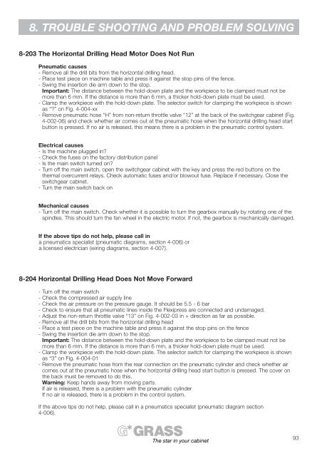
8. TROUBLE SHOOTING AND PROBLEM SOLVING<br />
8-203 The Horizontal Drilling Head Motor Does Not Run<br />
Pneumatic causes<br />
- Remove all <strong>the</strong> drill bits from <strong>the</strong> horizontal drilling head.<br />
- Place test piece on machine table and press it against <strong>the</strong> stop pins of <strong>the</strong> fence.<br />
- Swing <strong>the</strong> insertion die arm down to <strong>the</strong> stop.<br />
Important: The distance between <strong>the</strong> hold-down plate and <strong>the</strong> workpiece to be clamped must not be<br />
more than 6 mm. If <strong>the</strong> distance is more than 6 mm, a thicker hold-down plate must be used.<br />
- Clamp <strong>the</strong> workpiece with <strong>the</strong> hold-down plate. The selector switch for clamping <strong>the</strong> workpiece is shown<br />
as “?” on Fig. 4-004-xx<br />
- Remove pneumatic hose “H” from non-return throttle valve “12” at <strong>the</strong> back of <strong>the</strong> switchgear cabinet (Fig.<br />
4-002-06) and check whe<strong>the</strong>r air comes out at <strong>the</strong> pneumatic hose when <strong>the</strong> horizontal drilling head start<br />
button is pressed. If no air is released, this means <strong>the</strong>re is a problem in <strong>the</strong> pneumatic control system.<br />
Electrical causes<br />
- Is <strong>the</strong> machine plugged in?<br />
- Check <strong>the</strong> fuses on <strong>the</strong> factory distribution panel<br />
- Is <strong>the</strong> main switch turned on?<br />
- Turn off <strong>the</strong> main switch, open <strong>the</strong> switchgear cabinet with <strong>the</strong> key and press <strong>the</strong> red buttons on <strong>the</strong><br />
<strong>the</strong>rmal overcurrent relays. Check automatic fuses and/or blowout fuse. Replace if necessary. Close <strong>the</strong><br />
switchgear cabinet.<br />
- Turn <strong>the</strong> main switch back on<br />
Mechanical causes<br />
- Turn off <strong>the</strong> main switch. Check whe<strong>the</strong>r it is possible to turn <strong>the</strong> gearbox manually by rotating one of <strong>the</strong><br />
spindles. This should turn <strong>the</strong> fan wheel in <strong>the</strong> electric motor. If not, <strong>the</strong> gearbox is mechanically damaged.<br />
If <strong>the</strong> above tips do not help, please call in<br />
a pneumatics specialist (pneumatic diagrams, section 4-006) or<br />
a licensed electrician (wiring diagrams, section 4-007).<br />
8-204 Horizontal Drilling Head Does Not Move Forward<br />
- Turn off <strong>the</strong> main switch<br />
- Check <strong>the</strong> compressed air supply line<br />
- Check <strong>the</strong> air pressure on <strong>the</strong> pressure gauge. It should be 5.5 - 6 bar<br />
- Check to ensure that all pneumatic lines inside <strong>the</strong> Flexipress are connected and undamaged.<br />
- Adjust <strong>the</strong> non-return throttle valve “13” on Fig. 4-002-03 in + direction as far as possible.<br />
- Remove all <strong>the</strong> drill bits from <strong>the</strong> horizontal drilling head<br />
- Place a test piece on <strong>the</strong> machine table and press it against <strong>the</strong> stop pins on <strong>the</strong> fence<br />
- Swing <strong>the</strong> insertion die arm down to <strong>the</strong> stop.<br />
Important: The distance between <strong>the</strong> hold-down plate and <strong>the</strong> workpiece to be clamped must not be<br />
more than 6 mm. If <strong>the</strong> distance is more than 6 mm, a thicker hold-down plate must be used.<br />
- Clamp <strong>the</strong> workpiece with <strong>the</strong> hold-down plate. The selector switch for clamping <strong>the</strong> workpiece is shown<br />
as “3” on Fig. 4-004-01<br />
- Remove <strong>the</strong> pneumatic hose from <strong>the</strong> rear connection on <strong>the</strong> pneumatic cylinder and check whe<strong>the</strong>r air<br />
comes out at <strong>the</strong> pneumatic hose when <strong>the</strong> horizontal drilling head start button is pressed. The cover on<br />
<strong>the</strong> back must be removed to do this.<br />
Warning: Keep hands away from moving parts.<br />
If air is released, <strong>the</strong>re is a problem with <strong>the</strong> pneumatic cylinder<br />
If no air is released, <strong>the</strong>re is a problem in <strong>the</strong> control system.<br />
If <strong>the</strong> above tips do not help, please call in a pneumatics specialist (pneumatic diagram section<br />
4-006).<br />
The star in your cabinet<br />
93