INSTALLATION GUIDE - Hubbell Power Systems
INSTALLATION GUIDE - Hubbell Power Systems
INSTALLATION GUIDE - Hubbell Power Systems

Create successful ePaper yourself
Turn your PDF publications into a flip-book with our unique Google optimized e-Paper software.
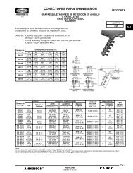
<strong>INSTALLATION</strong> <strong>GUIDE</strong>®3000Fit channel to frameAdd end cap adaptersCenter channel in trenchDrive rebar into place Add another channel Add frameInsert lumber diaphragms Place grating Ready to pour concrete!Concrete encasement can be placed in a single lift!®
TIPSInstallation TipsGeneral Installation Tips• Lubricate installation chair bolt threads with WD-40 ® beforeloosening.• Ensure channel sidewalls do not hang up on the installationchair grooves during frame to channel fastening. If thisoccurs apply inward pressure against the channel body and"pop" the channel into the grooves. Check each frame asyou go 4 places.• During frame installation run dry wall screw heads in closebut do not tighten. Tightening screws will cause frames tomisalign.• When cutting channel couplers to fit various channel sizes,cut off the coupler ends below the bottom most lip of thechannel frame (channel sidewall height minus approx.1 1/2") and then secure each end of the coupler to thechannel with sheet rock screws.• When installing end caps onto small channel sizes, removethe female (inside) portion that interferes with the frame.This can be done using the tools recommended in the ToolsNeeded list. Cut the end caps flush with the top of the frameto prevent wet concrete from entering the channel.• Wrapping the gratings with one wrap of clear 4 mil plasticwrap keeps the channel and grate clean during concretingand allows the wood diaphragms to be easily installed.Clear, thin plastic wrap allows the installer to see throughthe grate openings to find the frame guide slots and also todrive the wooden boards through the plastic without cutting.Parts Needed Per Channel(Available from Polycast)• 1 Channel• Channel coupler (1 per channel joint)• End cap adapters (2 per run)• 2 Frames• 4 Grates(Supplied by Others)• 8 #5 Rebar stakes• #6 x 1 1/4" long dry wall screws with fine threads (approx. 8)• Clear 4 mil plastic wrap to wrap grates• 8 standard 1" x 6" (3/4" x 5 1/2") planks x 24" longTools Needed (Supplied by Others)• Grounding rod driver or sledge hammer• Cordless drill• Dry wall screw bits• 1/2" nut driver bit• WD-40 ® lubricating fluid• 1/2" wrench• One 6' lg. 2" x 4" or two 12" lg. 4" x 4" boards• Small hack saw or straight blade fine tooth saw with spareblades- 2 -
Installation Benefits• POLYCAST ® 3000 installs quickly and easily without pre-assembly orhardware. A two person crew can easily install this drain using simplematerials available at most job sites.• Integral installation chair designed into the frame system holds the rebarto allow the entire assembly to be easily adjusted to grade.• Installation rates of 100 linear feet per hour and more are possible.Quicker set-up and installation reduces overall costs.BENEFITS- 3 -
Recommended Installation ProcedureNOTE: BEGIN <strong>INSTALLATION</strong> AT OUTLET (deepest) ENDStep 1. PreparationAdjust rebar straps on frames so the bolts are attached to the frame by only the first few threads. Straps should remain loose and able to easilymove back and forth on the bolts. Build two reusable lumber spacers by cutting a 2" x 4" x 6' long piece of lumber into six equal 12" pieces. Nailpieces together to make two 4" x 4" x 12" units. Cut 1" x 6" lumber planks to appropriate lengths as needed for diaphragms (can trim for shorterchannels or let stick through grates - See Step 19).NOTE: 8 diaphragms are needed per channel.Step 2. Excavation and System LayoutPROCEDUREExcavate sub-base to allow a minimum of 4" of concrete underneath and on both sides of the finished drain system. For ease of installation, a24" wide excavation is recommended. Slope the bottom of the excavation to approximately follow the slope of the POLYCAST ® 3000 channels.It is often helpful at this point to set an alignment "string line" over the proposed trench run to indicate the top of slab elevation. Lay channels,frames, gratings, couplers and other accessories next to the excavation, lined up as they are to be put in the trench.Step 3. Align & Assemble FramesLay two prepared frames end to end and face down. Align tongue of first frame with slot on second frame (see Detail 3A).Step 4. Trim couplerTrim coupler to match depth of shallow end ofchannel, minus approximately 1 1/2".- 4 -
Recommended Installation ProcedureStep 5. Secure Channel to FrameTo attach frame to channel, align and place one wall of the channel into appropriateslot by allowing the wall to lay against the inner placement tabs and slide down intoslot. Repeat procedure with other side of channel.Step 6. Install End Cap (for connection to 8" PVC only)NOTE: Skip this step if channel opens directly into a catch basin.Align end cap with frame and channel. Trim end cap to match top of frame. Notch endcap to allow tongue of frame to protrude (as shown in Detail 6A). This will allow end capto fit snugly against frame. Cut out end cap opening before placing it on the channel.PROCEDURE- 5 -
Recommended Installation ProcedureStep 7. Fasten End Cap and Coupler to ChannelPress end cap and coupler on matching ends of channel. Fasten end cap and coupler tochannel with three #6 x 1-1/4" long dry wall screws as shown (see Detail 7A and 7B).Next, fasten frames to channel, end cap and coupler with six #6 dry wall screws (see Detail7C, 7D and 7E). Important Note: Install sheet rock screws with heads close to frame. Do nottighten (frame installation only).PROCEDUREStep 8. Place Channel Assembly in ExcavationLay the two reusable lumber spacers from Step 1 in the bottom of theexcavation. Lower the channel assembly with bulb of channel down into theditch on top of the wood. Be sure marked flow arrows are facing in the properdirection.- 6 -
Recommended Installation ProcedureStep 9. Adjust to Top of SlabSlide pre-cut #5 rebar between the straps and the frame chair sidewalls for embedment into soil to preventfloating of channel as concrete is poured. Align and drive rebar into the excavation with the frame chair.Adjust the channel to top of slab and tighten the straps securely around the rebar. Remove the lumber spacersand place the next channel. Be sure that the top of the rebar is flush with the lower bend of the frame chair(below the slab as shown in Detail 9A) when the final grade is achieved.CAUTION: Channel liftingforces created by placement of wetconcrete are substantial. It is importantthe #5 rebar stakes penetrate the substrate deepenough to ensure channel anchorage. If uncompactedsoil conditions exist, channel encasement should beaccomplished in a 2-lift pour. The first lift should justcover the top of the bulb section.PROCEDUREStep 10. Prepare Additional ChannelsTrim coupler to match depth of shallow end of nextchannel. Press coupler onto channel and fastenwith a #6 x 1-1/4" long dry wall screw (as shown inDetail 10A).- 7 -
Recommended Installation ProcedureStep 11. Adding Next ChannelMove lumber from under previous channeland into position for placement of this channel.Place this channel into excavation with bulbdown and marked flow arrows facing theoutlet direction. Align end of new channel withchannel coupler of previous channel. Insertnext channel into coupler of previous channeland attach with dry wall screw.PROCEDUREStep 12. Place Frame Onto ChannelsWhile holding channel steady, place frames onto channel ensuring channel is placed properlybetween frame tabs. Make sure mating tongues of the frame are able to be interlocked with newframe. Fasten frames to channel, couplers and previous channel's frame with six dry wall screwsas shown in details. Do not tighten screws as this can cause misalignment of frames.- 8 -
Recommended Installation ProcedureStep 13. Adjust to Top of SlabSlide pre-cut #5 rebar between the straps and the frame chair sidewalls forembedment into soil to prevent floating of channel as concrete is poured.When proper positioning has been achieved, drive rebar into the excavationbottom until top of rebar is flush with the lower bend of the frame chair (belowslab as shown in Step 9).PROCEDUREStep 14. The Last ChannelInsert last channel into coupler of previous channel with shallowend exposed.- 9 -
Recommended Installation ProcedureStep 15. Final FramesPlace final frames onto channel.PROCEDUREStep 16. End CapAlign end cap with frame and channel. Trim end cap to match topof frame. Notch end cap to allow tongue of frame to protrude (asshown in Detail 16A). This will allow end cap to fit snugly againstframe and channel.- 10 -
Recommended Installation ProcedureStep 17. Attach Final End Cap and FramesWhile holding channel steady, press endcap snugly onto channel. Install #6 drywall screws securing channel, frame andend cap. Also fasten the channel andend cap together by screwing a dry wallscrew through the bottom of the channeland through the end cap flange.Step 18. Adjust Final Channel to GradeSlide pre-cut #5 rebar between the straps and the frame chairsidewalls for embedment into soil to prevent floating of channelas concrete is poured. When proper positioning has beenachieved, drive rebar into the excavation bottom until top of rebaris flush with the lower bend of the frame chair (below slab asshown in Step 9). Remove lumber spacers.PROCEDURE- 11 -
Recommended Installation ProcedureStep 19. Installing Wood DiaphragmsNOTE: THIS IS REQUIRED!Slide lumber spacers (can trim for shorter channelsor let extend through grates) into appropriateslots found in frame. All 4 slots in each individualframe must contain a diaphragm to ensure desiredresults. This procedure must be completed for theentire drain system.PROCEDUREStep 20. Wrap GratesWrap grates in plastic and place onframes of system before concreteis poured.- 12 -
Recommended Installation ProcedureStep 21. Pour Concrete and FinishPour concrete and after theconcrete has achieved sufficientcure, remove grates anddiaphragms. Knock off protruding endsof dry wall screws(a hammer works well for this).NOTE: Do not radius the edge of theconcrete adjacent to the drain.NOTE: Concrete encasement can beplaced in a single lift.Step 22. Clean UpAfter excess screw threads have been removed, unwrapgrates and place in frames. If locking devices arerequired, install them at this time(see Detail 22A).PROCEDURE- 13 -
Typical Installation DetailsDETAILS- 14 -
Typical Installation DetailsDETAILS- 15 -
STOCKING DISTRIBUTORSTHROUGHOUT NORTH AMERICA® POLYCAST ®3621 Industrial Park DriveLenoir City, TN 37771Phone: 800-346-3061 or 865-986-9726Fax: 865-986-0585Web: http://www.polycastdrain.come-mail: hpsliterature@hps.hubbell.com©Copyright 2008NOTE: Because <strong>Hubbell</strong> has a policy of continuous product improvement, we reserve the right to change design and specifications without notice.PC-10December, 2008SUTH 3M 03/08