

Installation Manual - Tarantula Security - Soundstream
Installation Manual - Tarantula Security - Soundstream
Installation Manual - Tarantula Security - Soundstream

You also want an ePaper? Increase the reach of your titles
YUMPU automatically turns print PDFs into web optimized ePapers that Google loves.
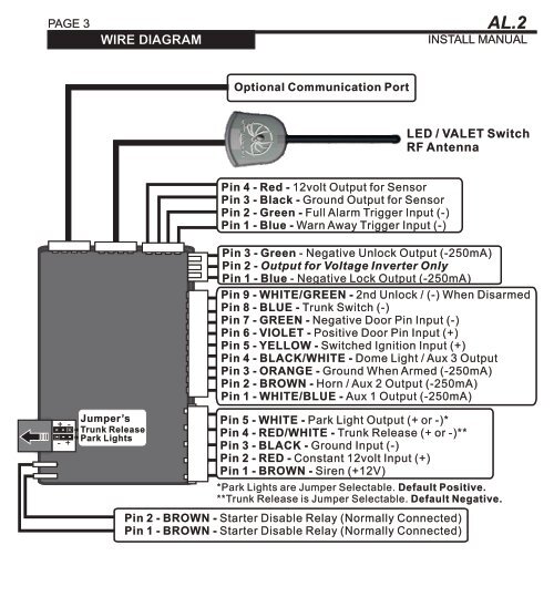
PAGE 3SYSTEM PROGRAMMING WIRE DIAGRAM- Menu 1AL.2INSTALL MANUALOptional Communication PortLED / VALET SwitchRF AntennaPin 4 - Red - 12volt Output for SensorPin 3 - Black - Ground Output for SensorPin 2 - Green - Full Alarm Trigger Input (-)Pin 1 - Blue - Warn Away Trigger Input (-)Pin 3 - Green - Negative Unlock Output (-250mA)Pin 2 - Output for Voltage Inverter OnlyPin 1 - Blue - Negative Lock Output (-250mA)Pin 9 - WHITE/GREEN - 2nd Unlock / (-) When DisarmedPin 8 - BLUE - Trunk Switch (-)Pin 7 - GREEN - Negative Door Pin Input (-)Pin 6 - VIOLET - Positive Door Pin Input (+)Pin 5 - YELLOW - Switched Ignition Input (+)Pin 4 - BLACK/WHITE - Dome Light / Aux 3 OutputPin 3 - ORANGE - Ground When Armed (-250mA)Pin 2 - BROWN - Horn / Aux 2 Output (-250mA)Pin 1 - WHITE/BLUE - Aux 1 Output (-250mA)+ -- +Jumper’sTrunk ReleasePark LightsPin 5 - WHITE - Park Light Output (+ or -)*Pin 4 - RED/WHITE - Trunk Release (+ or -)**Pin 3 - BLACK - Ground Input (-)Pin 2 - RED - Constant 12volt Input (+)Pin 1 - BROWN - Siren (+12V)*Park Lights are Jumper Selectable. Default Positive.**Trunk Release is Jumper Selectable. Default Negative.Pin 2 - BROWN - Starter Disable Relay (Normally Connected)Pin 1 - BROWN - Starter Disable Relay (Normally Connected)