Direct Numerical Simulation of Autoiginition of a Hydrogen Jet in a ...
Direct Numerical Simulation of Autoiginition of a Hydrogen Jet in a ...
Direct Numerical Simulation of Autoiginition of a Hydrogen Jet in a ...

Create successful ePaper yourself
Turn your PDF publications into a flip-book with our unique Google optimized e-Paper software.
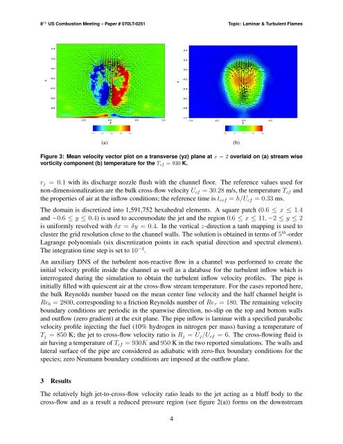
8 th US Combustion Meet<strong>in</strong>g – Paper # 070LT-0251 Topic: Lam<strong>in</strong>ar & Turbulent Flames(a)(b)Figure 3: Mean velocity vector plot on a transverse (yz) plane at x = 2 overlaid on (a) stream wisevorticity component (b) temperature for the T cf = 930 K.r j = 0.1 with its discharge nozzle flush with the channel floor. The reference values used fornon-dimensionalization are the bulk cross-flow velocity U cf = 30.28 m/s, the temperature T cf andthe properties <strong>of</strong> air at the <strong>in</strong>flow conditions; the reference time is t ref = h/U cf = 0.33 ms.The doma<strong>in</strong> is discretized <strong>in</strong>to 1,591,752 hexahedral elements. A square patch (0.6 ≤ x ≤ 1.4and −0.6 ≤ y ≤ 0.4) is used to accommodate the jet and the region 0.6 ≤ x ≤ 11, −2 ≤ y ≤ 2is uniformly resolved with δx = δy = 0.4. In the vertical z-direction a tanh mapp<strong>in</strong>g is used tocluster the grid resolution close to the channel walls. The solution is obta<strong>in</strong>ed <strong>in</strong> terms <strong>of</strong> 5 th -orderLagrange polynomials (six discretization po<strong>in</strong>ts <strong>in</strong> each spatial direction and spectral element).The <strong>in</strong>tegration time step is set to 10 −4 .An auxiliary DNS <strong>of</strong> the turbulent non-reactive flow <strong>in</strong> a channel was performed to create the<strong>in</strong>itial velocity pr<strong>of</strong>ile <strong>in</strong>side the channel as well as a database for the turbulent <strong>in</strong>flow which is<strong>in</strong>terrogated dur<strong>in</strong>g the simulation to obta<strong>in</strong> the turbulent <strong>in</strong>flow velocity pr<strong>of</strong>iles. The pipe is<strong>in</strong>itially filled with quiescent air at the cross-flow stream temperature. For the cases reported here,the bulk Reynolds number based on the mean center l<strong>in</strong>e velocity and the half channel height isRe b = 2800, correspond<strong>in</strong>g to a friction Reynolds number <strong>of</strong> Re τ = 180. The rema<strong>in</strong><strong>in</strong>g velocityboundary conditions are periodic <strong>in</strong> the spanwise direction, no-slip on the top and bottom wallsand outflow (zero gradient) at the exit plane. The pipe <strong>in</strong>flow is lam<strong>in</strong>ar with a specified parabolicvelocity pr<strong>of</strong>ile <strong>in</strong>ject<strong>in</strong>g the fuel (10% hydrogen <strong>in</strong> nitrogen per mass) hav<strong>in</strong>g a temperature <strong>of</strong>T j = 850 K; the jet to cross-flow velocity ratio is R j = U j /U cf = 6. The cross-flow<strong>in</strong>g fluid isair hav<strong>in</strong>g a temperature <strong>of</strong> T cf = 930K and 950 K <strong>in</strong> the two reported simulations. The walls andlateral surface <strong>of</strong> the pipe are considered as adiabatic with zero-flux boundary conditions for thespecies; zero Neumann boundary conditions are imposed at the outflow plane.3 ResultsThe relatively high jet-to-cross-flow velocity ratio leads to the jet act<strong>in</strong>g as a bluff body to thecross-flow and as a result a reduced pressure region (see figure 2(a)) forms on the downstream4