The radiomonitoring specialist - Rohde & Schwarz
The radiomonitoring specialist - Rohde & Schwarz
The radiomonitoring specialist - Rohde & Schwarz

Create successful ePaper yourself
Turn your PDF publications into a flip-book with our unique Google optimized e-Paper software.
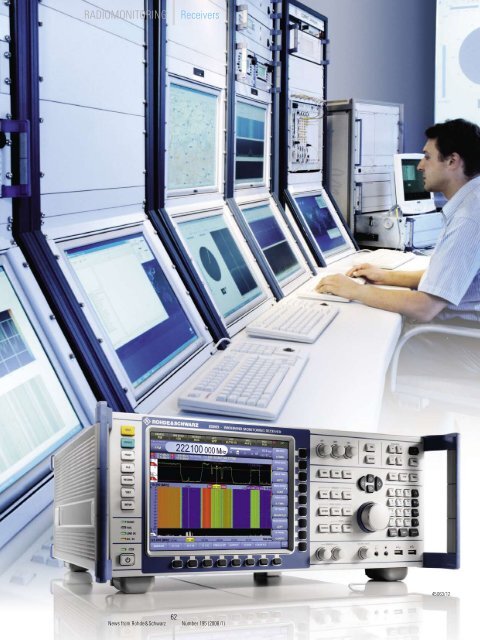
RADIOMONITORINGReceivers45063/1262News from <strong>Rohde</strong>&<strong>Schwarz</strong> Number 195 (2008/I)
R&S ® ESMD Wideband Monitoring Receiver<strong>The</strong> <strong>radiomonitoring</strong> <strong>specialist</strong>:versatile, fast, accurateFast detection of signals, highlyaccurate measurements and demodulation,and versatility are the majoradvantages of the new R&S ® ESMD<strong>radiomonitoring</strong> receiver. Due to theseadvantages plus other attributessuch as a wide frequency range andexpandability for use as a directionfinder, the R&S ® ESMD provides functionalitiespreviously available onlywith entire systems.Special characteristicsModern <strong>radiomonitoring</strong> equipment hasto handle a vast array of tasks, includingstationary or mobile use, widebandscan or narrowband demodulation, ormanual or fully automatic operation. <strong>The</strong>R&S ® ESMD (FIG 1) takes on all of thesechallenges easily with its wide range offunctions, its modular architecture, andits variety of available enhancements(FIG 2) – characteristics that allow usersto adapt the receiver optimally to theirindividual requirements. <strong>The</strong> specialcharacteristics of the R&S ® ESMD are asfollows:◆◆Large frequency range from 9 kHz to26.5 GHz◆◆Excellent RF performance◆◆Simple and quick operation via thefront panel◆◆Fast scan modes◆◆Gap-free IF spectrum up to 20 MHzbandwidth (realtime bandwidth)*◆◆Demodulation from 100 Hz to 20 MHz(realtime bandwidth)◆◆ITU-compliant measurement of signalparameters between 100 Hz and thefull realtime bandwidth◆◆Analog two-channel IF / video outputup to 20 MHz bandwidth◆◆Direction finding◆◆Standardized 1 Gbit Ethernet datainterface◆◆Standardized command set (SCPI)◆◆Easy serviceability and maintainabilityIn the base version, the R&S ® ESMDdetects frequencies from 20 MHz to3.6 GHz. Two frequency range expansionsare available for installation inthe instrument. With the expansionsfor the microwave range (3.6 GHz to26.5 GHz, SHF option) and the shortwaveband (9 kHz to 32 MHz, HF option), thereceiver can cover the entire frequencyrange from 9 kHz to 26.5 GHz. Up to sixantennas that are switched internallycan be connected in this configuration.FIG 1Shortwave or microwave, demodulation orspectrum display, detection of pulsed signals ordirection finding: <strong>The</strong> R&S ® ESMD provides allof these capabilities in one compact device.FIG 2 Simplified block diagram of the R&S ® ESMD system architecture.As system receiverSHF (option)Multi-option board (option)Multi-Gigabit linksWith front panelVHF/UHFHF (option)DC / DC (option)ADADAC/DCDSignalprocessingADA2.5 Gbit/s Local busHostprocessorEthernetswitchFront panel processorDisplay and operation* Maximum bandwidth that is processed withoutinterruption.63News from <strong>Rohde</strong>&<strong>Schwarz</strong> Number 195 (2008/I)Video / IFanalog2 × Ethernet10/100/1000Base T
RADIOMONITORINGReceivers<strong>The</strong> R&S ® ESMD offers excellent RF performanceover the entire receive range(see condensed data on page 67). Thisis of particular importance in scenarioswhere very strong and very weak signalsoccur closely together, or whenscanning for signals that are difficult todetect, because the user must be certainthat the correct signal is being detected,and not some artifact generated by thereceiver itself, for example.<strong>The</strong> R&S ® ESMD combines outstandingRF characteristics with innovative broadbandtechnology: For example, in the HFrange, it functions as a direct receiver.Its carefully designed preselection aswell as the absence of mixers, oscillators,and the like, make it a first-classreceiver, even in the shortwave rangeup to 32 MHz.Even though many <strong>radiomonitoring</strong> taskscan be carried out automatically thesedays, manual operation of the receiveris often indispensable. <strong>The</strong> R&S ® ESMDfront panel has been optimized for thesetypes of tasks (FIG 1). All important functions,including frequency entry, bandwidths,demodulation mode, AGC / MGC,and scan parameters, can be set usingfixed keys. <strong>The</strong> smooth-running frequencysetting knob makes tuning tosignals easy, and the high-resolution TFTdisplay (1024 × 768 pixels) ensures thatall device parameters and measurementresults are clearly visible (FIG 3).Whether you wish to monitor specificfrequencies or scan for difficult-to-detectsignals over a wide frequency range,fast scan modes are a must for everymodern <strong>radiomonitoring</strong> receiver. <strong>The</strong>R&S ® ESMD has three scan modes. <strong>The</strong>frequency scan is suited for sequentialscanning of a frequency band withfixed channel spacing. <strong>The</strong> memory scanprocesses up to 10000 channels in anysequence as defined by the operator.Both scan modes achieve speeds of upto 1000 channels/s.<strong>The</strong> highest scan rate is offered bythe R&S ® ESMD in the panorama scan(PSCAN) mode:Step width(kHz)Channels(1/s)Scan rate(GHz/s)100 200000 2050 360000 1825 560000 1412.5 800000 106.25 1000000 6.25Even at very small resolution bandwidths,the R&S ® ESMD achieves a scanrate of up to 20 GHz/s (FIG 4). As a result,the PSCAN is ideal for scanning both forshort-duration signals and for frequencyhoppers, even over wide scan ranges.FIG 3 Important tools in <strong>radiomonitoring</strong>: spectral and waterfall display (spectrogram).<strong>The</strong> 20 MHz wide spectrum shows four digital broadcast signals, one DVB-T signal to theleft and three DAB signals to the right. <strong>The</strong> high time resolution of the realtime spectrummakes the null symbols in the DAB data streams clearly visible in the waterfall display.FIG 4 PSCAN from 50 MHz to 1050 MHz: <strong>The</strong> step width (resolution bandwidth) is100 kHz. In this setting, the scan range (span) of 1 GHz is run through twenty times persecond. <strong>The</strong> left edge of the spectrum shows the VHF FM broadcast band, and the GSMband at 900 MHz is seen to the right.64News from <strong>Rohde</strong>&<strong>Schwarz</strong> Number 195 (2008/I)
Signal processing in realtime<strong>The</strong> digital signal processing in theR&S ® ESMD consists of two parallel,independently parameterized paths(FIG 5). One path calculates the IF spectrum,while the other path is used fordemodulation, automatic gain control(AGC), measurement value calculation,and reconversion to an analogsignal (video signal). Both paths workcompletely without interruption and inrealtime.<strong>The</strong> spectrum path allows reliable monitoringof the spectral characteristics foreven very quickly changing signals. Itseffectiveness becomes obvious whenmonitoring signals with a pulse structure(FIGs 6 to 8). <strong>The</strong> enormous amountof data obtained during spectrum calculationis difficult for externally connectedsystems to handle (FIG 9). <strong>The</strong>refore, thedevice already performs data reductionby means of various weighting filters(Average, MAXHOLD, MINHOLD).Even at small spectrum bandwidths, theuser benefits from the receiver’s processingpower: <strong>The</strong> signal processingoverlaps the spectrum calculations,which improves the time resolution.Alternatively, a weighted overlapf IF1IF signalB spectrumOverlap &windowingFFTAVG, MAX,MIN, CLRWWeightingIFspectrumADDUCDAIF videooutputB DemodDemodulationAGCSpectrumVideospectrumf IF2DSensorarrayAAudioMeasuredvaluesFIG 5Block diagram of the signal processing in the R&S ® ESMD.FIG 8 Analysis of a GSM signal using the IF spectrum: <strong>The</strong> signal to the right of thecenter shows an obvious peak. This is the frequency correction burst (FCB), which spectrallycorresponds to a carrier signal. <strong>The</strong> FCB is emitted only by GSM base stations, lasts576 µs, and is repeated every 46 ms or 51 ms.FIGs 6 and 7 Detection of long-range radar on the antenna: <strong>The</strong> distance of 500 kHzbetween the zeroes on the sin(x)/x-shaped spectrum leads one to suppose a pulselength of about 2 µs. <strong>The</strong> supposition is confirmed by measuring the amplitude-demodulatedsignal (envelope) using an oscilloscope connected to the analog video output ofthe R&S ® ESMD.65News from <strong>Rohde</strong>&<strong>Schwarz</strong> Number 195 (2008/I)
RADIOMONITORINGReceiversadd (WOLA) spectrum can be calculatedthat significantly improves the adjacentchannel suppression in the spectrum.<strong>The</strong> demodulation path is the method ofchoice when analyzing the time domaincharacteristics of signals. Because signalprocessing is carried out in parallel,the user can view radio signals from variousangles. <strong>The</strong> R&S ® ESMD simultaneouslyprovides the wideband, demodulated,and gain-controlled signal, as wellas a narrowband audio signal, varioussignal levels, and modulation parameterssuch as modulation depth and frequencydeviation. In addition, it calculatesthe spectrum of the demodulatedsignal. This video spectrum is extremelyhelpful in determining the characteristicsof signals (FIG 10), and it can evenbe useful in discerning some of the characteristicsof highly complex, spreadspectrum(DSSS) third-generation mobilesignals (FIG 11).Expandable for use asdirection finder<strong>The</strong> direction from which an electromagneticwave arrives at an antennais information whose importance cannotbe overestimated. <strong>The</strong> equipmentneeded to determine this angle of incidenceis normally both extensive andexpensive. Not so with the R&S ® ESMD:As the first monitoring receiver from<strong>Rohde</strong> & <strong>Schwarz</strong>, it can be upgradedto a full-featured direction finder(R&S ® DDF255) without any additionalequipment. Either the correlative interferometermethod or the Wattson-Wattprinciple is used to determine the bearing.Up to three DF antennas can be connecteddirectly to the receiver.Because the DF functionality is fully integratedinto the scan sequences, it satisfiesthe requirements for a variety ofscenarios. So whatever the situation –whether cyclical monitoring of distressfrequencies, interception of classic voicecommunications (FIG 12), or finding thebearing of short-duration signals in themillisecond range – the R&S ® ESMDfrom <strong>Rohde</strong> & <strong>Schwarz</strong> is an extremelycompact and cost-efficient solution.State-of-the-art and compatible:the system interfaces<strong>The</strong> R&S ® ESMD is equipped with twotriple-mode 1 GBit Ethernet interfacesfor data output and remote control(10 / 100 / 1000BaseT). As a result,backward compatibility with other<strong>Rohde</strong> & <strong>Schwarz</strong> monitoring receivers,such as the R&S ® EB200, R&S ® ESMB,R&S ® EM050, R&S ® EM550, R&S ® EM510,and R&S ® PR100, is ensured. And thesame applies to data and command formats.Seamless integration in existingmonitoring systems is thus no problemat all.FIG 10 Video spectrum of a frequency-demodulated VHF FM multiplex signal. This viewshows the structure of such a signal with 19 kHz pilot tone and RDS subcarrier.FIG 9 To allow the comparison of the realtime capability of monitoring receivers, avirtual scan speed is frequently specified. This value identifies the scan speed in scanranges that are smaller than the maximum bandwidth of the receiver. This could also becalled a realtime scan because the settling time of the synthesizer is immaterial withinthe realtime bandwidth of a receiver. At large bandwidths and a fixed frequency resolution,this quantity will only reflect the processing power of a receiver.Frequencyresolution (kHzNumber ofspectra (1/s)Time resolution(µs)Scan rate of realtimescan (B = 20 MHz)12.5 12500 80 250 GHz/s25 25000 40 500 GHz/s50 50000 20 1000 GHz/s100 100000 10 2000 GHz/s66News from <strong>Rohde</strong>&<strong>Schwarz</strong> Number 195 (2008/I)
<strong>The</strong> R&S ® ESMD has connections forexternal accessories, such as GPS or anelectronic compass. Like earlier devices,this receiver also offers comprehensiveselftests at the module level, ensuringa high degree of serviceability andmaintainability. Extensive recalibrationsafter a module replacement are thuseliminated.Both the modular design and the multioptionboards that allow implementationof future functionality enable theR&S ® ESMD to easily address new developmentsin <strong>radiomonitoring</strong> such aslarger realtime bandwidths.Paul RenardyMore information atwww.rohde-schwarz.com(search term: ESMD)SummaryShortwave or microwave, demodulationor spectrum display, detection ofpulsed signals or direction finding: <strong>The</strong>R&S ® ESMD provides all of these capabilitiesin one compact device. Becausethere are so many device options, thisarticle can offer only a brief overview ofthe receiver’s most important characteristics.<strong>The</strong> R&S ® ESMD and its expansionsoffer well over one hundred differentcombinations, making it adaptable toalmost any task. An upcoming issue willhighlight the most important options.Condensed data of the R&S ® ESMD (typical values)Frequency range9 kHz to 26.5 GHzNoise figureHF12 dBVHF10 dBUHF12 dB3rd order intercept point (IP3)HF35 dBm (at input level of –6 dBm)VHF23 dBmUHF23 dBmSynthesizer settling time1 msDemodulation modesAM, FM, ϕM, I/Q, PULSE, TV, LSB, USB, ISB, CWITU-compliant measurement valuesfrequency, frequency offset, frequency deviation,phase deviation, modulation depth, field strengthDemodulation and measurement bandwidths 31 bandwidths from 100 Hz to 20 MHzIF spectrum bandwidths14 bandwidths from 1 kHz to 20 MHzData interface 1 Gigabit Ethernet (10/100/1000Base T)Video / IF output (switchable)2 channels, gain-controlled, level >0 dBmFIG 11 Video spectrum of a UMTS signal. For digitally modulated signals whose envelopesare not constant, the baud rate or chip rate in the spectrum of the squared basebandsignal can be determined by means of spectral lines that are symmetrical tofrequency 0. In this case, this phenomenon occurs at a frequency of 3.84 MHz, whichcorresponds to the UMTS chip rate.FIG 12 <strong>The</strong> R&S ® ESMD after being upgraded to a direction finder: DF measurement ofa voice channel in the aeronautical radio band.67News from <strong>Rohde</strong>&<strong>Schwarz</strong> Number 195 (2008/I)