B-17 Pilots Manual.pdf
B-17 Pilots Manual.pdf
B-17 Pilots Manual.pdf

Create successful ePaper yourself
Turn your PDF publications into a flip-book with our unique Google optimized e-Paper software.
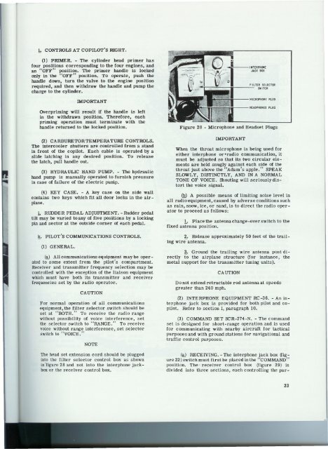
.,b CONTROLS AT COPILOT'S IDGHT.(1) PRIMER. - The cylinder head primer hasfour positions corresponding to the four engines, andan "OFF" position. The primer handle is lockedonly in "the "OFF" position. To operate, push thehandle down, turn the valve to the engine positionrequired, and then withdraw the handle and pump thecharge to the cylinder.IMPORTANTOverpriming will result if the handle is leftin the withdrawn position. Therefore, eachpriming operation must terminate with thehandle returned to the locked position.(2) CARBURETORTEMPERATURE CONTROLS.The intercooler shutters are controlled from a standin front of the copilot. Each cable is operated by aslide latching in any desired position. To releasethe latch, pull handle out.(3) HYDRAULIC HAND PUMP. - The hydraulichand pump is manually operated to furnish pressurein case of failure of the electric punip.(4) KEY CASE. - A key case on the side wallcontains two keys which fit all door locks in the airplane.i.. RUDDER PEDAL ADJUSTMENT. -Rudder pedaltilt may be varied to any of five positions by a lockingpin and sector at the outside corner of each pedal.~. PILOT'S COMMUNICATIONSCONTROLS.(1) GENERAL.@) All communications equipment may be operatedto some extent from the pilot's compartment.Receiver and transmitter frequency selection may becontrolled with the exception of the liaison equipmentwhich must have ~oth its transmitter and receiverfrequencies set by the radio operator.CAUTIONFor normal operation of all communicationsequipment, the filter selector switch should beset at "BOTH." To receive the radio rangewithout possibility of voice interference, setthe selector switch to "RANGE." To receivevoice without range interference, set selectorswitch to "VOICE."NOTEThe head set extension cord should be pluggedinto the filter selector control box as shownin'figure 28 and not into the interphone jackboxor the receiver control box.NICROPHOME PLUGHEADPHONESPLUGFigure 28 - Microphone and Headset PlugsIMPORTANTWhen the throat microphone is being used foreither interphone or-radio communication, itmust be adjusted so that its two circular elementsare held snugly against each side of thethroat just above the "Adam's apple." SPEAKSLOWLY, DISTINCTLY, AND IN A NORMALTONE OF VOICE. Shouting will seriously distortthe voice signal.(Q) A possible means of limiting noise level inall radio equipment, caused by adverse conditions suchas rain, snow, ice, or sand, is to direct the radio operatorto proceed as follows:1. Place the antenna change-over. switch to thefixed antenna position.~. Release approximately 50 feet of the trailingwire antenna.~. Ground the trailing wire antenna post directlyto. the airplane structure (for instance, themetal support for the transmitter tuning units).Do not extend retractablegreater than 240 mph.CAUTIONrod antenna at speeds(2) INTERPHONE EQUIPMENT RC-36. - An interphonejack box is provided for both pilot and copilot.Refer to section I, paragraph 10.(3) COMMAND SET SCR-274-N. - The commandset is designed for short-range operation and is usedfor communicating with nearby aircraft for tacticalpurposes and with ground stations for navigational andtraffic control purposes.(!0 RECEIVING. - The interphone jack box (figure22) switch must first be placed in the "COMMAND"position. The" receiver control box (figure 29) isdivided into three sections, each controlling the par-23