ApoTome - Carl Zeiss International
ApoTome - Carl Zeiss International
ApoTome - Carl Zeiss International

You also want an ePaper? Increase the reach of your titles
YUMPU automatically turns print PDFs into web optimized ePapers that Google loves.
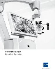
<strong>ApoTome</strong><br />
Microscopy from <strong>Carl</strong> <strong>Zeiss</strong><br />
Suddenly Everything Looks Different<br />
The Standard for Brilliant Images<br />
in 3D Fluorescence Imaging<br />
Änderungen vorbehalten.<br />
Gedruckt auf umweltfreundlich<br />
chlorfrei gebleichtem Papier.<br />
60-2-0002/d – gedruckt 04.08
1<br />
2<br />
3<br />
4<br />
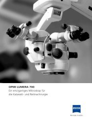
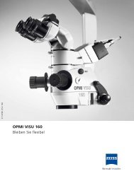
1) Triple fluorescence of a drosophila embryo, lower left:<br />
conventional fluorescence image, upper right: <strong>ApoTome</strong> mode<br />
Frank Josten and Michael Hoch, University of Bonn, Germany<br />
2) <strong>ApoTome</strong> mode and conventional image, hippocampus of<br />
the rat, triple fluorescence, maximum projection of a 3D image<br />
stack, Plan-APOCHROMAT 63x/1.4<br />
Eberhard Fuchs and Susanne Bauch, GPC Göttingen, Germany<br />
3) <strong>ApoTome</strong> mode and conventional image, multiple myeloma,<br />
triple fluorescence, C-APOCHROMAT 63x/1.2<br />
Peter Hutzler and Karin Bink, GSF Neuherberg, Germany<br />
4) 3D image stack, upper left: conventional image, lower right:<br />
<strong>ApoTome</strong> mode, Drosophila melanogaster embryo,<br />
double fluorescence, Plan-NEOFLUAR 40x/0.75<br />
Christian Klämbt, University of Münster, Germany<br />
2
Contents<br />
The Quality Factor:<br />
<strong>ApoTome</strong><br />
Where the Exceptional is Standard in 3D Imaging 4-5<br />
The Performance Factor:<br />
A Module That is More Than the Sum of Its Advantages 6-7<br />
The Image Quality Factor:<br />
The Visible Difference in Fluorescence Imaging 8-9<br />
The System Factor:<br />
Precise Interplay Reveals Everything in Great Detail 10-11<br />
The Intelligence Factor:<br />
AxioVision and <strong>ApoTome</strong><br />
New Perspectives for Life Sciences 12-14<br />
The Function Factor:<br />
Optical Sections by Means of Structured Illumination 15-17<br />
System Solutions from <strong>Carl</strong> <strong>Zeiss</strong><br />
<strong>ApoTome</strong> with Axio Observer and Axio Imager 18-19<br />
3
4<br />
The Quality Factor: <strong>ApoTome</strong>.<br />
Where the Exceptional is Standard in 3D Imaging.<br />
Innovation in 3D Imaging has a good name: <strong>ApoTome</strong>. With <strong>ApoTome</strong> <strong>Carl</strong> <strong>Zeiss</strong><br />
triggered a small revolution in fluorescence microscopy. Since then everything has<br />
been different.<br />
From an innovation to the standard<br />
in life science research<br />
In the meantime <strong>ApoTome</strong> has established itself as the<br />
standard method in high-end research in Life Sciences.<br />
Since the introduction of <strong>ApoTome</strong>, the problems associated<br />
with stray light from other focal planes have become<br />
a concern of the past. <strong>Carl</strong> <strong>Zeiss</strong> now offers outstanding<br />
technology for the generation of optical sections in 2D<br />
and 3D Fluorescence Imaging. Exceptional performance<br />
became the standard.<br />
• Exceptional in terms of contrast, image quality and<br />
resolution – with an optical section thickness of one<br />
Rayleigh unit<br />
• Exceptional ease of operation – extremely simple and<br />
flexible adaptation<br />
• Exceptional in its seamless integration – easy to implement<br />
in existing <strong>Carl</strong> <strong>Zeiss</strong> system solutions<br />
Optical sections for every application<br />
With <strong>ApoTome</strong> for the upright system solution<br />
Axio Imager and for the inverted research platform<br />
Axio Observer the new generation in light microscopy<br />
sets a new standard in 3D Imaging: optical sections in<br />
even complex applications; fascinating images, brilliant<br />
image quality, and undreamed-of possibilities for scientific<br />
analysis.<br />
Awarded the R&D 100 Award and the Innovation Price<br />
Photonics Circle of Excellence in 2003
AxioImager system with <strong>ApoTome</strong>, AxioCam MRm and AxioVision<br />
The name<br />
<strong>ApoTome</strong>, the innovation in 3D Imaging<br />
The module<br />
Slider technology for the <strong>Carl</strong> <strong>Zeiss</strong> Microscopes<br />
Axiovert 200, Axio Observer, Axioplan 2 imaging*<br />
and Axio Imager<br />
The performance<br />
New image quality and elevated contrast in the conventional<br />
fluorescence microscope<br />
Deblurred optical sections in thicker samples<br />
The price<br />
A cost-effective leap forward into an exceptional performance<br />
category of digital microscopy<br />
The principle<br />
Sophisticated technology for artifact-free structured<br />
illumination<br />
The positions<br />
Practice-oriented 2-in-1 slider for conventional fluorescence<br />
(position 1) and the <strong>ApoTome</strong> mode (position 2)<br />
for sophisticated digital microscopy<br />
The operation<br />
Quickly integrated<br />
Simple control principle due to high-performance<br />
technology<br />
Problem-free working in the familiar system environment<br />
The fluorescence<br />
Open for the entire spectrum of possible fluorescence dyes<br />
The system<br />
Perfectly coordinated with the high-performance components<br />
in the <strong>Carl</strong> <strong>Zeiss</strong> complete system: <strong>ApoTome</strong> –<br />
microscope – camera – software – PC<br />
The variants<br />
Cost-effective as complete system or as an upgrade for<br />
your existing system<br />
*All Axioplan 2 imaging microscopes delivered after February 2000. Serial<br />
numbers: from 35 11 000001; from 35 10 000001; from 35 02 000001<br />
5
6<br />
The Performance Factor: A Module That is<br />
More Than the Sum of Its Advantages.<br />
<strong>ApoTome</strong> is more than just the sum of its advantages, i.e. brilliant image quality,<br />
performance and speed, and an open spectrum of fluorescence dyes. Together<br />
with its ease of operation and practice-oriented design, all these benefits add up<br />
to a definitive increase in the performance of your Digital Imaging workstation.<br />
1A: the image quality<br />
One Rayleigh unit of optical section depth – this value<br />
represents highest optical resolution with an excellent<br />
signal-to-noise ratio. In the z-direction, the visible resolution<br />
is increased by a factor of 2 compared to conventional<br />
fluorescence microscopy. This allows generation of<br />
optical sections and 3D image reconstructions from the<br />
specimen. This is particularly crucial for thick specimens<br />
1<br />
2<br />
where it is also necessary to achieve optimum resolution<br />
and contrast in the x-, y-plane. The optimized algorithm<br />
for precise, artifact-free images is yet another benefit. In<br />
a nutshell, this means you will be working with maximum<br />
contrast, excellent image quality, deblurred image planes<br />
and, as a consequence, with more visible information for<br />
your analyses, documentations and publications.<br />
Optimized: the speed<br />
Three raw images are acquired for each optical section.<br />
The results are calculated online in less than 80 msec –<br />
depending on the image size used. The resulting image<br />
is immediately displayed on the monitor and is immediately<br />
available for further processing. Multichannel fluorescence<br />
and Z-stack images are acquired automatically.<br />
Flexible: optimum results with every objective<br />
Different applications require different objectives. In<br />
combination with <strong>ApoTome</strong> the best possible resolution<br />
is always achieved. If needed, the grid in <strong>ApoTome</strong> can<br />
be quickly and easily changed. A grid that is ideal for<br />
the objective and the application can be selected from<br />
three grids with different grid frequencies. The advantage<br />
is that in each case an optimum result with an optical<br />
section depth of approximately one Raleigh unit is<br />
achieved.<br />
1) Conventional, 2) <strong>ApoTome</strong> mode<br />
Mouse omentum (mesentery), double fluorescence,<br />
Plan-APOCHROMAT 20x/0.75<br />
Mike Tighe, Kim Kusser and Troy Randall, Trudeau Institute,<br />
New York, USA
Innovative LED fluorescent light source Colibri, fast,<br />
flexible, without mechanical switching<br />
Position 1: Iris diaphragm, position 2: <strong>ApoTome</strong> mode<br />
1<br />
2<br />
No limits: the fluorescence dyes and light sources<br />
<strong>ApoTome</strong> can be combined with all light sources used<br />
in fluorescence microscopy. HBO illumination is ideal as<br />
an economical entry-level solution. The metal halogenide<br />
lamp HXP 120 does not require adjustment, and offers a<br />
long service life and a very homogenous illumination. The<br />
brand new Colibri LED light source from <strong>Carl</strong> <strong>Zeiss</strong> generates<br />
exceptionally high-contrast fluorescence images<br />
with a high dynamic range. Extremely long-lasting LEDs<br />
emit only the desired wavelength range. Consequently,<br />
undesired light does not even have to be suppressed at<br />
all. <strong>ApoTome</strong> provides nearly unlimited flexibility in the<br />
selection of fluorescence dyes. System technology does<br />
not determine whether you work with DAPI, FITC, rhodamine,<br />
Cy5 or with vital dyes such as GFP or mRFP. You<br />
decide.<br />
Plug and go: ease of operation<br />
Simply slide <strong>ApoTome</strong> into the field diaphragm plane<br />
of the reflected-light beam path of your microscope.<br />
<strong>ApoTome</strong> offers you two positions: position 1 – the iris<br />
diaphragm for the Koehler illumination in the reflectedlight<br />
beam path; position 2 – the <strong>ApoTome</strong> grid for optical<br />
sections with brilliant image quality. The operation<br />
is just as simple as the insertion. Set <strong>ApoTome</strong> to the<br />
appropriate position, iris diaphragm or <strong>ApoTome</strong> mode –<br />
depending on what your application requires. The slider<br />
remains in your microscope and is thus always ready to<br />
use and protected.<br />
Advanced technology: the image acquisition modes<br />
Advanced technology for brilliant images and greatest<br />
sample protection: <strong>ApoTome</strong> calculates your images<br />
directly online, which allows you immediate access to<br />
the optical sections. However, <strong>ApoTome</strong> also allows the<br />
preparation of raw data. Thus, you can also process images<br />
generated with this module offline with different<br />
settings. The advantage is that images of very sensitive<br />
specimens must only be acquired once. With the aid of<br />
a specially adapted deconvolution, the resolution of the<br />
raw data can be further increased for perfect results with<br />
every sample.<br />
7
1 2<br />
8<br />
The Image Quality Factor: The Visible Difference<br />
in Fluorescence Imaging.<br />
Experience the difference: <strong>ApoTome</strong> brings Fluorescence Imaging to a new level<br />
of performance – with excellent image quality, fascinating images, and new<br />
perspectives for science and research.<br />
Decoding gene functions<br />
In Drosophila research, wild type and mutant embryos are<br />
frequently compared with each other in various stages of<br />
development. In the case of the mutants, genes playing a<br />
specific role in developing or maintaining bodily functions<br />
have been manipulated. The comparative study allows<br />
conclusions to be drawn about gene functions in certain<br />
1) Conventional, 2) <strong>ApoTome</strong> mode<br />
Drosophila melanogaster embryo, double fluorescence, EC Plan-NEOFLUAR 40x/1.3<br />
George Scaria, University of Illinois at the Chicago Medical School, USA<br />
developmental processes. The images below show the<br />
development of Drosophila melanogaster embryos at a<br />
relatively early stage subsequent to fertilization. All the<br />
cells are in the same cycle of cell division. In the <strong>ApoTome</strong><br />
mode, the spindle microtubules (red), which separate the<br />
chromosomes (blue), can be clearly identified.
1<br />
1) Conventional, 2) <strong>ApoTome</strong> mode<br />
Sprouting axons of a dorsal root<br />
ganglia explant, triple fluorescence,<br />
Plan-APOCHROMAT 20x/0.75<br />
Investigation of neuronal circuits<br />
Studies in developmental neurobiology include the examination<br />
of how nerve cells developing in a certain part<br />
of the body connect with cells in a completely different<br />
part of the body. The connection is made by means of<br />
long cell processes, known as axons, which, by exploring<br />
their environment, e.g., along a chemical gradient, find<br />
their way through the tissue to their target cells. This process<br />
occurs primarily during the embryonic development<br />
of an organism. In order to decode these highly specific<br />
and extremely complex mechanisms, zebrafish research<br />
1) Conventional, 2) <strong>ApoTome</strong> mode<br />
Zebrafish (Danio rerio), triple fluorescence, Plan-APOCHROMAT 20x/0.75<br />
Monika Marx and Martin Bastmeyer, University Karlsruhe, Germany<br />
1 2<br />
also uses mutants. These are compared with wild type<br />
individuals to identify the genes which are crucial for this<br />
connection. These findings are of major significance for<br />
clinical questions. This example shows the head region of<br />
a zebrafish embryo (Danio rerio). In the <strong>ApoTome</strong> mode,<br />
two different populations of neurons can be clearly distinguished<br />
by the red and green marking. The nuclei are<br />
marked using DAPI.<br />
Additional applications, images and additional movies<br />
are to be found at: www.zeiss.de/apotome<br />
2<br />
9
10<br />
The System Factor: Precise Interplay Reveals<br />
Everything in Great Detail<br />
<strong>Carl</strong> <strong>Zeiss</strong> offers a broad range of system components which all have one thing in<br />
common: when used in combination with <strong>ApoTome</strong>, they fully utilize all of the<br />
possibilities of Fluorescence Imaging. From research microscopes with brilliant<br />
optics, via high-performance cameras and the comprehensive AxioVision software<br />
platform, all system components are perfectly coordinated with one another.<br />
Optimized for fluorescence:<br />
Axio Observer and Axio Imager<br />
The high-end systems Axio Imager und Axio Observer<br />
combined with <strong>ApoTome</strong> are ideal research platforms for<br />
3D Imaging.<br />
• Fully motorized microscope for high-end research<br />
• Apochromatically corrected fluorescence beam path<br />
for brilliant image quality in Multichannel Image<br />
Acquisition<br />
Axio Imager system with <strong>ApoTome</strong>, AxioCam and AxioVision<br />
• Z-focus with a resolution of 10 nm and high reproducibility<br />
• Sophisticated ergonomics for comfortable microscopy<br />
• TFT display for optimum ease of operation<br />
Particularly appropriate for long-term experiments even<br />
with living cells: Axio Observer with diverse, modular<br />
and fully integrated incubation solutions. The hardwarebased<br />
focus stablizer Definite Focus ensures stable focus<br />
positions even under the most difficult conditions.
Powerful even in weak fluorescence:<br />
the cameras<br />
AxioCam is the leading generation of Peltier-cooled digital<br />
cameras from <strong>Carl</strong> <strong>Zeiss</strong>. These cameras feature highest<br />
sensitivity, a resolution of 1.4 megapixels in AxioCam MRm<br />
or up to 13 megapixels in AxioCam HRm, and a dynamic<br />
range of up to 1 : 2200 or 1 : 2500 in 12 or 14 bit, respectively,<br />
as well as maximum image quality. Custom<br />
tailored to your applications in fluorescence microscopy<br />
naturally in monochrome version – and at a convincing<br />
price-performance ratio.<br />
Axio Observer system with <strong>ApoTome</strong>, AxioCam and AxioVision<br />
Efficient in research and routine applications:<br />
the microscope control<br />
Using the <strong>Carl</strong> <strong>Zeiss</strong> AxioVision software platform, you<br />
are able to control all motorized microscope systems<br />
from <strong>Carl</strong> <strong>Zeiss</strong> interactively and fully automatically. The<br />
advantage is simple and efficient operation and clarity of<br />
the user interface. The microscope’s setting parameters<br />
can be saved as required and retrieved again at any time<br />
AxioVision determines magnifications automatically, and<br />
complex acquisition modes are easy to configure. As a<br />
consequence, your results can be reliably reproduced.<br />
11
12<br />
The Intelligence Factor: AxioVision and <strong>ApoTome</strong>.<br />
New Perspectives for Life Sciences.<br />
<strong>ApoTome</strong> and AxioVision – an outstanding combination. AxioVision is the software<br />
platform from <strong>Carl</strong> <strong>Zeiss</strong> for all requirements in Fluorescence Imaging – from twodimensional<br />
imaging up to the sixth dimension. Any combination of x, y, z, lambda,<br />
time lapse and different sample positions is possible for automatic image acquisition.<br />
And with <strong>ApoTome</strong> in AxioVision, optical sections are available in every mode.<br />
Multichannel Fluorescence<br />
Using this module, in connection with <strong>ApoTome</strong>, you<br />
can acquire multichannel images automatically with high<br />
contrast and optimum quality. One channel is acquired<br />
using the optimum exposure time for each excitation<br />
wavelength. The grid is also focused automatically for<br />
each fluorescence wavelength. Every channel of the optical<br />
section is calculated online. The advantage is that you<br />
see the results immediately, for example, colocalization<br />
of fluorescence dyes in thick specimens.<br />
User interface for multichannel images Gallery view of a Z-stack<br />
Z-Stack<br />
Using this module you can acquire and display different<br />
focal planes of a specimen as an image stack – with high<br />
precision and accurately reproducible. <strong>ApoTome</strong> controls<br />
the acquisition of the three raw images. The optical section<br />
is calculated online in every plane. Consequently, it<br />
is possible for you to see the result quickly.<br />
Time Lapse<br />
Observing specimens, studying and recording changes<br />
over time, documenting the results clearly – the Time<br />
Lapse module enables you to control acquisition and the<br />
microscope with precision.
Muscle-specific GFP labeling (yellow), nuclear labeling (blue), developmental stage of<br />
10.5 days, double fluorescence Z-stack image in <strong>ApoTome</strong> mode,<br />
Plan-NEOFLUAR 5x/0.15<br />
Dr. Frederic Relaix and Emanuelle Perret, PFID, Pasteur Institute, Paris, France<br />
MosaiX<br />
Using this module and a motorized x-, y-stage, even large<br />
specimens which extend beyond the field of view can<br />
be displayed with high resolution and high contrast. The<br />
specimen is scanned automatically in order to generate<br />
a large composite image. This electronically generated<br />
image of the specimen provides a complete representation<br />
of the sample, and can be used as a basis for further<br />
analysis.<br />
Mark&Find<br />
Mark&Find automatically acquires images at several<br />
locations in a specimen, e.g. over time. With this module<br />
you mark several locations in your specimen, which<br />
you subsequently, repeatedly, and exactly relocate during<br />
the experiment. In this manner you increase the data<br />
throughput and efficiency in long experiments.<br />
Above left: Conventional fluorescence image acquisition, lower right: optical section<br />
with <strong>ApoTome</strong>, Platynereis dumerili, triple fluorescence (DAPI, Phalloidin-Alexa488,<br />
alpha-Tubulin Alexa555), maximum intensity projection of a 3D image stack,<br />
Plan-APOCHROMAT 20x/0.8<br />
V. Wilkens, University of Osnabrück, Germany<br />
HDR Image Acquisition<br />
Sometimes even the high dynamic range of the best<br />
cameras is inadequate. If you desire to simultaneously<br />
examine very light and dark areas in your specimen,<br />
HDR (High Dynamic Range) Image Acquisition provides<br />
the solution. In HDR mode several images with different<br />
exposure times are combined to form an image with increased<br />
dynamic range. Thus, all the details in an image<br />
are reproduced.<br />
Inside4D<br />
In combination with <strong>ApoTome</strong>, Inside4D makes multi-<br />
dimensional visualization and presentation of cells and<br />
tissue sections exceptionally easy. <strong>ApoTome</strong> generates<br />
the optical sections online. You can then visualize the<br />
data in Inside4D immediately. 3D reconstructions can be<br />
viewed from any angle. With this module you can visualize<br />
the structural context in the specimen. And you have<br />
an excellent tool for the production of movies at your<br />
disposal – for the best possible presentation of your 3D<br />
images in the Internet, with PowerPoint TM , or with many<br />
other media.<br />
13
Neuromuscular synapses in the sternomastoid muscle of a rat, triple fluorescence Z-stack<br />
Dr. Le Tian, Dr. Wes Thompson, University of Texas, Austin, USA<br />
Measurement and analysis<br />
Measure your specimens in two or three dimensions,<br />
manually or automatically. Various AxioVision modules<br />
help you perform these tasks. Intensity or area measurements,<br />
segmentations or colocalizations can be automatically<br />
or interactively determined. Volumes, surfaces<br />
or distances can also be measured in three-dimensional<br />
image stacks. It is comfortable in its range of functions<br />
and easy to operate.<br />
Fast MosaiX<br />
Dual Camera<br />
Digital<br />
High Speed<br />
Recorder<br />
HDR Imaging<br />
Fast<br />
Acquisition<br />
Widefield<br />
Multichannel<br />
Unmixing<br />
Image acquisition Image<br />
Processing<br />
Imaging Plus ASSAYbuilder<br />
Panorama Mark&Find <strong>ApoTome</strong> 3D Measure TMA<br />
MosaiX Time Lapse 3D<br />
Deconvolution<br />
Extended<br />
Focus<br />
Autofocus Multichannel<br />
Fluorescence<br />
Z-Stack 2D<br />
Deconvolution<br />
ELISPOT<br />
Image Analysis<br />
SFM<br />
QuantiFISH Ratio Tracking<br />
AutoMeasure AutoMeasure<br />
Plus<br />
Inside4D Interactive<br />
Measurement<br />
Combinations<br />
All these modules can be freely combined with one another<br />
and form system solutions which are designed to<br />
address an extremely wide range of requirements. The<br />
result is the cost-effective adaptation of the solution to<br />
your application without unnecessary investments.<br />
PowerPoint TM is a product of Microsoft ® .<br />
Online<br />
Measurement<br />
2) 3D distance measurement from the surface on one yeast particle to<br />
the surface of the next one. Cells: RAW 264.7 Macrophages with nuclear<br />
staining (blue), actin staining (red) and zymosan yeast particle (green)<br />
Dr. Birgit Kraus, University of Regensburg, Germany<br />
Colocalization<br />
Physiology Asset<br />
Archive<br />
Documen-<br />
tation<br />
VBA<br />
Commander<br />
Configuration<br />
14
15<br />
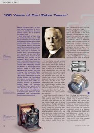
Schematic of beam path<br />
The fluorescence excitation light passes through two glass plates in the <strong>ApoTome</strong> slider.<br />
There is a grid structure on the first glass plate; the grid pattern is “imprinted” in the<br />
excitation light. The second glass plate is tilted by a scanning mechanism, thereby<br />
slightly shifting the beam path with the imprinted grid pattern. The excitation light<br />
(green) with the grid pattern is then projected onto the specimen via a conventional<br />
fluorescence filter set. The emission light (red) is collected by the objective and imaged<br />
onto the camera sensor.<br />
Please visit our educational website www.zeiss.com/campus if you are interested to<br />
see how <strong>ApoTome</strong> works and to view <strong>ApoTome</strong> application images.
16<br />
The Function Factor: Optical Sections by Means<br />
of Structured Illumination.<br />
<strong>ApoTome</strong> has continuously proven its leadership position in Fluorescence Imaging<br />
and has received numerous awards from specialist groups. The functional principle<br />
used by <strong>ApoTome</strong> to generate optical sections is structured illumination, which is so<br />
well-engineered that it provides artifact-free images.<br />
<strong>ApoTome</strong>: the grid pattern creates clarity<br />
In the <strong>ApoTome</strong> mode, a grid structure is inserted into the<br />
light field diaphragm plane of the reflected-light beam<br />
path (page 17, Fig. 1A). The grid structure is precisely imaged<br />
into the object plane; it is clearly visible through the<br />
eyepieces and in the live image. In a second step, a highprecision<br />
scanning mechanism moves the grid pattern in<br />
defined steps across the sample plane. In the third step,<br />
images are acquired at each grid position (Figs. 1A-C).<br />
Finally, a single resulting image is calculated from the<br />
three raw images using a fast mathematical algorithm<br />
(Fig. 1D). The result is a precise optical section through<br />
the specimen with no blurring, with elevated contrast,<br />
and perfect for 3D reconstructions.<br />
Precisely in focus: the calibration<br />
A fundamental challenge in generating precise, deblurred<br />
optical sections using structured illumination is to precisely<br />
focus the grid for the selected objective and fluorescence<br />
wavelength. This is very easy with <strong>ApoTome</strong>.<br />
You start an interactive assistant in AxioVision, and it<br />
An interactive dialog guides you once through the calibration<br />
of the grid focus<br />
guides you through the calibration process step by step.<br />
And in the apochromatic fluorescence beam path of<br />
Axio Imager and Axio Observer, the grid only has to be<br />
shifted minimally or not at all for the different fluorescent<br />
wavelengths.<br />
Interior view of the <strong>ApoTome</strong> slider: iris diaphragm in position 1, grid and planparallel glass plate in position 2
Fig. 1.: Schematic depiction of the grid projection in a fluorescence specimen<br />
A-C: Raw images with different positions of the grid<br />
D: Optical section through the specimen<br />
Background<br />
In conventional fluorescence microscopy, the image<br />
always consists of signal contributions coming from the<br />
focused object plane and from the structures located<br />
above and below it. The blurred structures from above<br />
or below are either perceived as being out of focus or, if<br />
they are clearly outside the focal plane, have the effect<br />
of brightening the image background, which reduces<br />
image contrast.<br />
The “structured illumination” principle<br />
In the “structured illumination” process used in <strong>ApoTome</strong>,<br />
a grid is inserted into the field diaphragm plane of the<br />
fluorescence beam path. Superimposing the projected<br />
grid onto the fluorescent sample generates an image of<br />
the specimen that has dark grid lines running through it<br />
Section thicknesses with <strong>ApoTome</strong> when used with Axio Imager<br />
(Fig. 1A). Outside the focal plane the grid is also blurred,<br />
thus no grid projection is visible in defocused specimen<br />
structures (Fig. 1A, arrow). In the context of image analysis,<br />
this provides a criterion for differentiating in-focus<br />
object structures from those which are defocused. The<br />
determination of the grid contrast as a function of the<br />
location (xy) can thus be used to calculate an optical section<br />
(Fig. 1D). In order to reconstruct all the image information,<br />
at least three raw images with different positions<br />
of the grid projections must be acquired (Figs. 1 A-C: grid<br />
shift marked by blue line).<br />
Literature: Schäfer, L. et. al.: Structured Illumination Microscopy:<br />
Artifact analysis and reduction utilizing a parameter optimization<br />
approach. J. Microsc. 216 (2004) pp.165<br />
Objective Magn. NA Immersion Recmd. grid Section thickness at 490 nm (RU/μm)<br />
EC Plan-NEOFLUAR 10x/0.3 10 0.3 Air L1 1.01 / 11.04<br />
EC Plan-NEOFLUAR 20x/0.5 20 0.5 Air M 1.03 / 4.05<br />
EC Plan-NEOFLUAR 40x/0.75 40 0.75 Air H1 1.09 / 1.89<br />
EC Plan-NEOFLUAR 40x/1.3 Oil 40 1.3 Oil M 1.07 / 0.94<br />
EC Plan-NEOFLUAR 63x/0.95 Korr. 63 0.95 Oil H1 0.7 / 0.76<br />
EC Plan-NEOFLUAR 63x/1.25 Oil 63 1.25 Oil H1 1.08 / 1.03<br />
EC Plan-NEOFLUAR 100x/1.3 Oil 100 1.3 Oil H1 0.71 / 0.63<br />
LCI Plan-NEOFLUAR 25x/0.8 Imm. Korr. 25 0.8 Oil, water or glycerin L1 1.01 / 2.26<br />
LCI Plan-NEOFLUAR 63x/1.3 Imm. Korr. 63 1.3 Water or glycerin H1 1.05 / 0.88<br />
Plan-APOCHROMAT 10x/0.45 10 0.45 Air L1 1.45 / 6.88<br />
Plan-APOCHROMAT 20x/0.8 20 0.8 Air L1 1.08 / 1.65<br />
Plan-APOCHROMAT 40x/0.95 Korr. 40 0.95 Air H1 1.07 / 1.16<br />
Plan-APOCHROMAT 40x/1.0 Oil 40 1.0 Oil M 0.97 / 1.45<br />
Plan-APOCHROMAT 40x/1.3 Oil 40 1.3 Oil M 1.07 / 0.94<br />
Plan-APOCHROMAT 63x/1.0 W 63 1.0 Water H1 0.93 / 1.22<br />
Plan-APOCHROMAT 63x/1.4 Oil 63 1.4 Oil H1 1.06 / 0.81<br />
Plan-APOCHROMAT 100x/1.4 Oil 100 1.4 Oil H1 0.7 / 0.53<br />
LD LCI Plan-APOCHROMAT 25x/0.8 25 0.8 Oil, water or glycerin L1 0.88 / 1.35<br />
C-APOCHROMAT 10x/0.45 W 10 0.45 Water L1 1.46 / 9.40<br />
C-APOCHROMAT 40x/1.2 W 40 1.2 Water M 0.94 / 0.85<br />
C-APOCHROMAT 63x/1.2 W 63 1.2 Water H1 0.95 / 0.86<br />
LD C-APOCHROMAT 40x/1.1 W 40 1.1 Water M 0.94 / 1.02<br />
αPlan-FLUAR 100x/1.45 Oil 100 1.45 Oil H1 0.67 / 0.48<br />
αPlan-APOCHROMAT 100x/1.46 Oil 100 1.46 Oil H1 0.67 / 0.47<br />
*Analogously to the definition of the Rayleigh unit (distance from the PSF’s maximum to its first minimum)<br />
17
18<br />
<strong>ApoTome</strong> is compatible with the following <strong>Carl</strong> <strong>Zeiss</strong> stands:<br />
Axioplan 2 imaging (serial numbers: from 35 11 000001; from<br />
35 10 000001; from 35 02 000001), Axio Imager.D1 and<br />
Axio Imager.Z1, Axio Imager.A2, Axio Imager.M2, Axio Imager.D2<br />
and Axio Imager.Z2, Axiovert 200M, Axio Observer.A1,<br />
Axio Observer.D1 and Axio Observer.Z1
For optimum results we recommend the use of chromatically highly<br />
corrected objectives, e.g. of the Plan-NEOFLUAR, Plan-APOCHROMAT,<br />
or C-APOCHROMAT series.<br />
Use of <strong>ApoTome</strong> in connection with Phase Contrast objectives is not<br />
generally recommended, since the phase ring blocks spatial frequencies<br />
in the image, which are important for the reconstruction of the<br />
optical section.<br />
You will find a detailed list of recommended objectives with recommendation<br />
of appropriate grids in the AxioVision Online Help.<br />
19
<strong>Carl</strong> <strong>Zeiss</strong> MicroImaging GmbH<br />
07740 Jena, Germany<br />
BioSciences | Göttingen Location<br />
change.<br />
Phone : +49 551 5060 660<br />
to<br />
Telefax : +49 551 5060 464<br />
subject<br />
E-Mail : micro@zeiss.de<br />
www.zeiss.de/apotome Information<br />
Printed on environmentally friendly<br />
bleached without cholorine.<br />
60-2-0025/e – printed 01.09