OPERATION AND SERVICE MANUAL Supra 550 650 750 850 & 950
Service Manual - SEA BOX
Service Manual - SEA BOX

Create successful ePaper yourself
Turn your PDF publications into a flip-book with our unique Google optimized e-Paper software.
<strong>OPERATION</strong> <strong>AND</strong><strong>SERVICE</strong> <strong>MANUAL</strong>FOR<strong>Supra</strong> <strong>550</strong>, <strong>650</strong>, <strong>750</strong>, <strong>850</strong> & <strong>950</strong>TRUCK REFRIGERATION UNITS
TABLE OF CONTENTSPARAGRAPH NUMBERPageGENERAL SAFETY NOTICES ............................................................ Safety-1FIRST AID ............................................................................. Safety-1OPERATING PRECAUTIONS ............................................................ Safety-1MAINTENANCE PRECAUTIONS .......................................................... Safety-1SPECIFIC WARNING <strong>AND</strong> CAUTION STATEMENTS ........................................ Safety-1DESCRIPTION ............................................................................... 1-11.1 INTRODUCTION ..................................................................... 1--11.2 GENERAL DESCRIPTION ............................................................. 1--61.3 CONDENSING SECTION ............................................................. 1--61.3.1 Drive Equipment .................................................................. 1--61.3.2 Condensing Section Refrigeration System ............................................ 1--71.4 EVAPORATOR SECTION ............................................................. 1--101.4.1 Thermal Expansion Valve .......................................................... 1--101.4.2 Heat Exchanger ................................................................... 1--101.4.3 Evaporator Coil ................................................................... 1--101.4.4 Electric and Water Heat ............................................................ 1--101.5 SYSTEM OPERATING CONTROLS <strong>AND</strong> COMPONENTS ................................. 1--111.5.1 Switches And Controls ............................................................. 1--111.6 UNIT SPECIFICATIONS ............................................................... 1--121.6.1 Engine Data ....................................................................... 1--121.6.2 Compressor Data ................................................................. 1--141.6.3 Refrigeration System Data .......................................................... 1--141.6.4 Electrical Data .................................................................... 1--151.6.5 TORQUE VALUES ................................................................ 1--151.7 SAFETY DEVICES ................................................................... 1--161.8 REFRIGERANT CIRCUIT ............................................................. 1--171.8.1 Cooling (See Figure 1-13) .......................................................... 1--171.8.2 Heat And Defrost (See Figure 1-13) ................................................. 1--17i 62--10828
TABLE OF CONTENTSPARAGRAPH NUMBERPage<strong>OPERATION</strong> ................................................................................. 2-12.1 MICROPROCESSOR CONTROLLER ................................................... 2--12.1.1 Introduction ...................................................................... 2--12.2 MICROPROCESSOR CONFIGURATION ................................................ 2--22.3 DESCRIPTION OF MICROPROCESSOR COMPONENTS ................................ 2--22.3.1 Keypad .......................................................................... 2--22.3.2 Digital Display .................................................................... 2--32.4 <strong>OPERATION</strong> ......................................................................... 2--32.4.1 Pre-Trip Inspection ................................................................ 2--32.4.2 Starting - Road Operation .......................................................... 2--42.4.3 Starting - Standby Motor Drive ...................................................... 2--42.4.4 Manual Start ...................................................................... 2--42.4.5 Pre-Trip .......................................................................... 2--42.4.6 Setpoint .......................................................................... 2--42.4.7 Start/Stop Operation ............................................................... 2--52.4.8 Continuous Run Operation ......................................................... 2--52.4.9 Defrost Cycle ..................................................................... 2--52.4.10 Functional Parameters ............................................................. 2--62.4.11 Unit Data ......................................................................... 2--72.4.12 Alarm Display ..................................................................... 2--92.4.13 Stopping Instructions .............................................................. 2--11CONTROL LOGIC <strong>AND</strong> TEMPERATURE CONTROL ............................................. 2-13.1 MODES OF <strong>OPERATION</strong> ............................................................. 3--13.1.1 Startup and Pull Down -- Engine Operation ........................................... 3--13.1.2 Startup and Pull Down -- Standby Operation .......................................... 3--13.1.3 Null Mode Overrides ............................................................... 3--13.1.4 Dual Probe Operation .............................................................. 3--23.1.5 Fuel Heater Operation ............................................................. 3--23.1.6 Defrost Mode ..................................................................... 3--23.1.7 Unloading in Temperature Mode ..................................................... 3--33.1.8 Auto Diesel Restart (Option) ........................................................ 3--53.2 SEQUENCE OF <strong>OPERATION</strong> .......................................................... 3--53.2.1 Engine Drive ...................................................................... 3--53.2.2 Standby .......................................................................... 3--63.2.3 Auto Start Sequence .............................................................. 3--662--10828ii
TABLE OF CONTENTSPARAGRAPH NUMBERPageCONTROL LOGIC <strong>AND</strong> TEMPERATURE CONTROL ............................................. 3-13.1 MODES OF <strong>OPERATION</strong> ............................................................. 3-13.1.1 Startup and Pull Down -- Engine Operation ........................................... 3-13.1.2 Startup and Pull Down -- Standby Operation .......................................... 3-13.1.3 Null Mode Overrides ............................................................... 3-13.1.4 Dual Probe Operation .............................................................. 3-23.1.5 Fuel Heater Operation ............................................................. 3-23.1.6 Defrost Mode ..................................................................... 3-23.1.7 Suction Pressure Control Mode ..................................................... 3-23.1.8 Auto Diesel Restart (Option) ........................................................ 3-33.2 SEQUENCE OF <strong>OPERATION</strong> .......................................................... 3-33.2.1 Engine Drive ...................................................................... 3-33.2.2 Standby .......................................................................... 3-43.2.3 Auto Start Sequence .............................................................. 3-4<strong>SERVICE</strong> .................................................................................... 4-1MAINTENANCE SCHEDULE <strong>Supra</strong> <strong>550</strong> ...................................................... 4--1MAINTENANCE SCHEDULE <strong>Supra</strong> <strong>650</strong>/ <strong>750</strong>/ <strong>850</strong> .............................................. 4--2MAINTENANCE SCHEDULE <strong>Supra</strong> <strong>950</strong> ....................................................... 4--2OIL CHANGE INTERVALS .................................................................. 4--24.1 SERVICING ENGINE RELATED COMPONENTS ......................................... 4--44.1.1 Cooling System ................................................................... 4--44.1.2 Changing Lube Oil and Lube Oil Filters ............................................... 4--44.1.3 Replacing the Speed and Run Control Solenoids ...................................... 4--54.1.4 Engine Air Cleaner ................................................................ 4--54.1.5 Fuel Filter and Fuel Circuit .......................................................... 4--64.1.6 Servicing Glow Plugs .............................................................. 4--74.1.7 Alternator ........................................................................ 4--74.2 SERVICING <strong>AND</strong> ADJUSTING V-BELTS ................................................ 4--84.2.1 Belt Tension Gauge ................................................................ 4--84.2.2 Alternator V-Belt .................................................................. 4--84.2.3 Water Pump Belt Tensioner ......................................................... 4--84.2.4 Standby Motor--Compressor V-Belt .................................................. 4--94.2.5 Engine--Compressor V-Belts ........................................................ 4--94.3 INSTALLING MANIFOLD GUAGE SET .................................................. 4--94.3.1 Preparing Manifold Gauge/Hose Set For Use ......................................... 4--94.3.2 Connecting Manifold Gauge/Hose Set ................................................ 4--94.3.3 Removing the Manifold Gauge Set .................................................. 4--94.4 PUMPING THE UNIT DOWN .......................................................... 4--104.5 REFRIGERANT LEAK CHECKING ..................................................... 4--104.6 EVACUATION <strong>AND</strong> DEHYDRATION .................................................... 4--104.6.1 General .......................................................................... 4--104.6.2 Preparation ....................................................................... 4--104.6.3 Procedure for Evacuation and Dehydrating System .................................... 4--11iii 62--10828
TABLE OF CONTENTSPARAGRAPH NUMBERPage<strong>SERVICE</strong> (Continued) ........................................................................ 4-14.7 CHARGING THE REFRIGERATION SYSTEM ........................................... 4--114.7.1 Checking the Refrigerant Charge .................................................... 4--114.7.2 Installing a Complete Charge ....................................................... 4--114.7.3 Adding A Partial Charge ............................................................ 4--124.8 REPLACING THE COMPRESSOR ..................................................... 4--134.9 COMPRESSOR OIL LEVEL ........................................................... 4--134.9.1 Checking Oil Level ................................................................ 4--134.9.2 Adding Oil with Compressor in System ............................................... 4--134.9.3 Adding Oil to Service Replacement Compressor ....................................... 4--144.10 COMPRESSOR UNLOADER VALVE .................................................... 4--154.11 CHECKING <strong>AND</strong> REPLACING FILTER-DRIER ........................................... 4--154.12 CHECKING <strong>AND</strong> REPLACING HIGH PRESSURE SWITCH ............................... 4--154.12.1 Replacing High Pressure Switch ..................................................... 4--154.12.2 Checking High Pressure Switch ..................................................... 4--164.13 CHECKING CALIBRATION OF THE DEFROST AIR SWITCH .............................. 4--164.14 CHECKING <strong>AND</strong> REPLACING EVAPORATOR FAN MOTOR BRUSHES & COMMUTATOR .... 4--174.15 EVAPORATOR COIL CLEANING ....................................................... 4--174.16 CONDENSER COIL CLEANING ........................................................ 4--174.17 SOLENOID VALVES ................................................................... 4--174.17.1 <strong>Supra</strong> <strong>550</strong>/<strong>650</strong>/<strong>750</strong>/<strong>850</strong> 3--Way Valve ................................................ 4--174.17.2 Hot Gas Valve (HGS2) and 3--Way Valve for <strong>Supra</strong> <strong>950</strong> (HGS2 not used on <strong>950</strong>) .......... 4--184.18 ADJUSTING THE COMPRESSOR PRESSURE REGULATING VALVE (CPR) ................ 4--184.19 THERMOSTATIC EXPANSION VALVE .................................................. 4--194.20 MICROPROCESSOR CONTROLLER ................................................... 4--204.21 MICROPROCESSOR REPLACEMENT and CONFIGURATION ............................ 4--204.21.1 To Remove and Replace Microprocessor Logic Board: ................................. 4--204.21.2 To Reach The Configuration Fields From The Keypad: ................................. 4--214.22 CONTROLLER SENSOR CHECKOUT .................................................. 4--214.23 SUCTION PRESSURE TRANSDUCER .................................................. 4--2462--10828iv
TABLE OF CONTENTSPARAGRAPH NUMBERPageTROUBLESHOOTING ......................................................................... 5-15.1 DIESEL ENGINE ..................................................................... 5--15.1.1 Engine Will Not Start .............................................................. 5--15.1.2 Engine Starts Then Stops .......................................................... 5--15.1.3 Starter Motor Malfunction .......................................................... 5--15.1.4 Malfunction In the Engine Starting Circuit ............................................. 5--25.2 ALTERNATOR ....................................................................... 5--25.3 REFRIGERATION .................................................................... 5--35.3.1 Unit Will Not Cool ................................................................. 5--35.3.2 Unit Runs But Has Insufficient Cooling ............................................... 5--35.3.3 Unit Operates Long or Continuously in Cooling ........................................ 5--35.3.4 Unit Will Not Heat or Has Insufficient Heating ......................................... 5--35.3.5 Defrost Cycle Malfunction .......................................................... 5--45.3.6 Abnormal Pressure ................................................................ 5--45.3.6.1 Cooling .................................................................... 5--45.3.6.2 Heating ................................................................... 5--55.3.7 Abnormal Noise .................................................................... 5--55.3.8 Control System Malfunction ......................................................... 5--55.3.9 No Evaporator Air Flow or Restricted Air Flow ......................................... 5--55.3.10 Expansion Valve Malfunction ........................................................ 5--65.3.11 Hot Gas (Three-Way) Valve Malfunction .............................................. 5--65.4 Standby Motor Malfunction ............................................................. 5--6SCHEMATIC DIAGRAMS ...................................................................... 6-16.1 INTRODUCTION ..................................................................... 6-1v 62--10828
LIST OF ILLUSTRATIONSFIGURE NUMBERPageFigure 1-1. Condensing Section -- Top View/Cab Command ....................................... 1--2Figure 1-2. Unit Curbside View ................................................................ 1--3Figure 1-3. Unit Roadside View ............................................................... 1--3Figure 1-4. Electrical Box ..................................................................... 1--4Figure 1-5. Relay/Fuse Board (With All Optional Components) .................................... 1--5Figure 1-6. 70 Amp Alternator (P/N 30-60050-04) ................................................ 1--7Figure 1-7. Cylinder Head -- Unloaded ......................................................... 1--7Figure 1-8. Cylinder Head -- Loaded ........................................................... 1--8Figure 1-9 Accumulator ...................................................................... 1--8Figure 1-10. Hot Gas Valve -- Cooling Flow ...................................................... 1--9Figure 1-11. Hot Gas Valve -- Heat and Defrost Flow .............................................. 1--9Figure 1-12. Water and Electric Heat Components ................................................ 1--10Figure 1-13. Refrigeration Circuit ............................................................... 1--18Figure 2-1. Cab Command ................................................................... 2--1Figure 3-1. Auto Start Sequence .............................................................. 3--7Figure 3-2. Temperature Control Sequence -- Continuous Mode ................................... 3--8Figure 3-3. Temperature Control Sequence -- Start / Stop Mode ................................... 3--9Figure 3-4. Temperature Control Sequence -- Continuous Mode ................................... 3--10Figure 3-5. Temperature Control Sequence -- Start / Stop Mode ................................... 3--11Figure 4-1. Coolant System ................................................................... 4--4Figure 4-2. Speed and Run Control Solenoids ................................................... 4--5Figure 4-3. Fuel System ..................................................................... 4--6Figure 4-4. Electric Fuel Pump ................................................................ 4--6Figure 4-5. 70 Amp Alternator ................................................................. 4--7Figure 4-6. V-Belt Arrangement ............................................................... 4--8Figure 4-7. Belt Tension Gauge ............................................................... 4--8Figure 4-8. Manifold Gauge Set ............................................................... 4--9Figure 4-9. Vacuum Pump Connection ......................................................... 4--11Figure 4-10. Procedure for Adding A Complete Charge ............................................ 4--12Figure 4-11. Procedure for Adding A Partial Charge ............................................... 4--12Figure 4-12. Compressor ...................................................................... 4--14Figure 4-13. Unloader Solenoid Valve ........................................................... 4--15Figure 4-14. Typical Setup for Testing High Pressure Switch ....................................... 4--16Figure 4-15. Defrost Air Switch Test Setup ....................................................... 4--16Figure 4-16. Fan Motor Brushes ................................................................ 4--17Figure 4-17. Hot Gas (Three-Way) Valve (<strong>Supra</strong> <strong>550</strong>/<strong>650</strong>/<strong>750</strong>/<strong>850</strong>) .................................. 4--17Figure 4-18. Hot Gas Valve (HGS2) and <strong>Supra</strong> <strong>950</strong> 3--Way Valve (HGS2 Shown) ..................... 4--18Figure 4-19. Compressor Pressure Regulating Valve .............................................. 4--18Figure 4-20. Thermostatic Expansion Valve ...................................................... 4--19Figure 4-21. Thermostatic Expansion Valve Bulb and Thermocouple ................................ 4--19Figure 6-1. Electrical Schematic Wiring Diagram ................................................ 6-262--10828vi
LIST OF TABLESTABLE NUMBERPageTable 1-1. Model Chart ..................................................................... 1--1Table 1-2. Additional Support Manuals ........................................................ 1--1Table 1-3. Fuse Identification ................................................................ 1--5Table 1-4. Relay Identification ................................................................ 1--5Table 1-5. Test Point Identification ............................................................ 1--6Table 1-9. Safety Devices -- Microprocessor Controller .......................................... 1--16Table 2-1. Manual Glow Time ................................................................ 2--4Table 2-1. Functional Parameters ............................................................. 2--7Table 2-2. Unit Data Codes .................................................................. 2--8Table 2-3. Alarm Display .................................................................... 2--9Table 3-1. Unloading in Temperature Mode .................................................... 3--3Table 4-1. Service Category Descriptions ...................................................... 4--3Table 4-2. Belt Tension (See Figure 4-7) ....................................................... 4--8Table 4-3. Connection Point Voltage .......................................................... 4--20Table 4-5. Sensor Resistance -- Micro Units (ATS,CDT, RAS, SAS & WTS) ........................ 4--24Table 4-6. R-404A Temperature--Pressure Chart ................................................ 4--25vii 62--10828
SAFETY SUMMARYGENERAL SAFETY NOTICESThe following general safety notices supplement the specific warnings and cautions appearing elsewhere in thismanual. They are recommended precautions that must be understood and applied during operation and maintenanceof the equipment covered herein. The general safety notices are presented in the following three sections labeled:First Aid, Operating Precautions and Maintenance Precautions. A listing of the specific warnings and cautionsappearing elsewhere in the manual follows the general safety notices.SAFETY PRECAUTIONSYour Carrier Transicold refrigeration unit has been designed with the safety of the operator in mind. During normaloperation, all moving parts are fully enclosed to help prevent injury. During all pre-trip inspections, daily inspections,and problem troubleshooting, you may be exposed to moving parts. Stay clear of all moving parts when the unit is inoperation and when the unit RUN/STOP Switch (RSS) is in the START/RUN position.FIRST AIDAn injury, no matter how slight, should never go unattended. Always obtain first aid or medical attention immediately.OPERATING PRECAUTIONSAlways wear safety glasses. Wear hearing protection as required.Keep hands, clothing and tools clear of the evaporator and condenser fans.No work should be performed on the unit until all circuit breakers and the RUN/STOP Switch are turned off, and batterypower supply is disconnected.Always work in pairs. Never work on the equipment alone.In case of severe vibration or unusual noise, stop the unit and investigate.MAINTENANCE PRECAUTIONSBeware of unannounced starting of the unit. This unit is equipped with Auto--Start in both the road and standby modes.The unit may start at any time. When performing any check of the system make certain the Emergency Switch is in theOFF position.Be sure power is turned off before working on motors, controllers, solenoid valves and electrical control switches. Tagcircuit breaker and vehicle ignition to prevent accidental energizing of circuit.Do not bypass any electrical safety devices, e.g. bridging an overload, or using any sort of jumper wires. Problems withthe system should be diagnosed, and any necessary repairs performed, by qualified service personnel.When performing any arc welding on the unit or container, disconnect all wire harness connectors from themicroprocessor. Do not remove wire harness from the modules unless you are grounded to the unit frame with a staticsafe wrist strap.In case of electrical fire, open circuit switch and extinguish with CO 2 (never use water).AUTO-STARTYour refrigeration unit is equipped with Auto-Start in both Start/Stop and Continuous Run modes. The unit may start atany time. A buzzer will sound for 5 seconds before the unit is started. When performing any check of the refrigerationunit (e.g., checking the belts, checking the oil), make certain that the RUN/STOP Switch is in the OFF (0) position.ENGINE COOLANTThe engine is equipped with a pressurized cooling system. Under normal operating conditions, the coolant in theengine and radiator is under high pressure and is very hot. Contact with hot coolant can cause severe burns. Do notremove the cap from a hot radiator; if the cap must be removed, do so very slowly in order to release the pressurewithout spray.REFRIGERANTSThe refrigerant contained in your unit can cause frostbite, severe burns, or blindness when in direct contact with theskin or eyes. For this reason, and because of legislation regarding the handling of refrigerants during system service,we recommend that you contact your nearest Carrier Transicold authorized repair facility whenever your unit requiresrefrigeration system service .Safety-162--10828
BATTERYThis unit is equipped with a lead-acid type battery. The battery normally vents small amounts of flammable hydrogengas. Do not smoke when checking the battery. A battery explosion can cause serious physical harm and/or blindness.SPECIFIC WARNING <strong>AND</strong> CAUTION STATEMENTSTo help identify the label hazards on the unit and explain the level of awareness each one carries, an explanation isgiven with the appropriate consequences:DANGER -- means an immediate hazard which WILL result in severe personal injury or death.WARNING -- means to warn against hazards or unsafe conditions which COULD result in severe personal injury ordeath.CAUTION -- means to warn against potential hazard or unsafe practice which could result in minor personal injury,product or property damage.The statements listed below are specifically applicable to this refrigeration unit and appear elsewhere in this manual.These recommended precautions must be understood and applied during operation and maintenance of the equipmentcovered herein.WARNINGBeware of unannounced starting of the engine, standby motor, evaporator fan or condenser fan. Theunit may cycle the engine, standby motor or fans unexpectedly as control requirements dictateWARNINGUnder no circumstances should ether or any other starting aids be used to start engine.WARNINGMake sure the power plug is clean and dry before connecting to any power source.Do not attempt to connect or remove power plug or perform service and/or maintenance before ensuringthe unit RUN/STOP Switch is in the STOP position and the I/O switch is in the “O” position.WARNINGBeware of V-belts and belt driven components as the unit may start automatically. Before servicingunit, make sure the Run-Stop switch is in the STOP position. Also disconnect the negative batterycable.WARNINGDo not use a nitrogen cylinder without a pressure regulator. Cylinder pressure is approximately 2350psi (160 bar). Do not use oxygen in or near a refrigerant system as an explosion may occur.WARNINGSince refrigerant traps a certain quantity of oil, to avoid oil loss during maintenance, add 50 cc ofPOE oil to the refrigeration system when any evacuation is performed.WARNINGEnsure power to the unit is OFF and power plug is disconnected or vehicle engine is OFF and negativebattery cable is disconnected before replacing the compressor.62--10828Safety-2
CAUTIONObserve proper polarity when installing battery, negative battery terminal must be grounded. Reversepolarity will destroy the rectifier diodes in alternator. As a precautionary measure, disconnectpositive battery terminal when charging battery in unit. Connecting charger in reverse will destroythe rectifier diodes in alternator.CAUTIONUnder no circumstances should anyone attempt to repair the microprocessor or the Logic or DisplayBoards. Should a problem develop with these components, contact your nearest Carrier Transicolddealer for replacement.CAUTIONUnit with R404A and POE oil, the use of inert gas brazing procedures is mandatory; otherwise compressorfailure will occur. For more information see Technical Procedure 98-50553-00 Inert Gas BrazingCAUTIONUse only ethylene glycol anti-freeze (with inhibitors) in system as glycol by itself will damage thecooling system.Always add pre-mixed 50/50 anti-freeze and water to radiator/engine. Never exceed more than a 50%concentration of anti-freeze. Use a low silicate anti-freeze.CAUTIONWhen changing oil filters, the new filters should be primed with clean oil. If the filters are not primed,the engine may operate for a period with no oil supplied to the bearings.CAUTIONWhen changing fuel filter, the new filter should be filled with clean fuel.CAUTIONTo prevent trapping liquid refrigerant in the manifold gauge set be sure set is brought to suctionpressure before disconnecting.Safety-362--10828
CAUTIONRefrigerant R404a is a blend. Charging as a vapor will change the properties of the refrigerant. Onlyliquid charging through the king valve is acceptable.CAUTIONExtreme care must be taken to ensure the manifold common connection remains immersed in oil atall times. Otherwise air and moisture will be drawn into the compressor.CAUTIONDo not damage or over tighten the enclosing tube assembly. Also make sure all parts are placed inthe enclosing tube in proper sequence to avoid premature coil burn-out.CAUTIONUnder no circumstances should a technician electrically probe the microprocessor at any point, otherthan the connector terminals where the harness attaches. Microprocessor components operate atdifferent voltage levels and at extremely low current levels. Improper use of voltmeters, jumperwires, continuity testers, etc. could permanently damage the microprocessor.CAUTIONMost electronic components are susceptible to damage caused by electrical static discharge (ESD).In certain cases, the human body can have enough static electricity to cause resultant damage to thecomponents by touch. This is especially true of the integrated circuits found on the microprocessor.CAUTIONUnder no circumstances should anyone attempt to service the microprocessor . Should a problemdevelop with the microprocessor, contact your nearest Carrier Transicold dealer for replacement.CAUTIONRefrigerant R404A must be charged as a liquid. Refrigerant R404A is a blend. Charging as a vapor willchange the properties of the refrigerant.62--10828Safety-4
SECTION 1DESCRIPTION1.1 INTRODUCTIONWARNINGBeware of unannounced starting of theengine, standby motor, evaporator fan orcondenser fan. The unit may cycle theengine, standby motor or fansunexpectedly as control requirementsdictateThis manual contains operating data, electrical data andservice instructions for the Carrier Transicold <strong>Supra</strong>model truck refrigeration units listed in Table 1-1.Additional <strong>Supra</strong> support manuals are listed inTable 1-2.The model/serial number plate is located inside the uniton the frame as shown in Figure 1-2.Table 1-1. Model ChartMODEL<strong>Supra</strong> <strong>550</strong>, TDB-13<strong>Supra</strong> <strong>550</strong>, TDS-13<strong>Supra</strong> <strong>650</strong>, TDB-16<strong>Supra</strong> <strong>650</strong>, TDS-16<strong>Supra</strong> <strong>750</strong>, TDB-19<strong>Supra</strong> <strong>750</strong>, TDS-19<strong>Supra</strong> <strong>850</strong>, TDB-24<strong>Supra</strong> <strong>850</strong>, TDS-24<strong>Supra</strong> <strong>950</strong>, TDB-36<strong>Supra</strong> <strong>950</strong>, TDS-36REFRIGERANTST<strong>AND</strong>BYR-404AENGINE COMPRESSOR MOTORLB KG 60 Hz9 4 CT2-29TV13 5.913 5.915 6.8CT3-44TVCT3-69TV05K 0122 Cylinder05K244 Cylinder05G376 Cylinder5.9 hp(4.4 kW)7.6 hp(5.7 kW)8.3 hp(6.2 kW)14.8 hp(11 kW)Table 1-2. Additional Support ManualsManual Number Equipment Covered Type of Manual62-10829 <strong>Supra</strong> <strong>550</strong> Parts List62-11091 <strong>Supra</strong> <strong>650</strong>,<strong>750</strong> Parts List62-11089 <strong>Supra</strong> <strong>850</strong> Parts List62-11092 <strong>Supra</strong> <strong>950</strong> Parts List62-10826 <strong>Supra</strong> 50 Series Easy to Run62-10827 <strong>Supra</strong> 50 Series Operator’s Manual62-02491 Compressor (05K012) Operation and Service62-02460 Compressor (05K4) Parts List62-02756 Compressor (05G) Operation and Service62-11052 Compressor (05G Twinport) Operation and Service62-10299 Compressor (05G) Parts List62-11053 Compressor (05G Twinport) Parts List1--1 62--10828
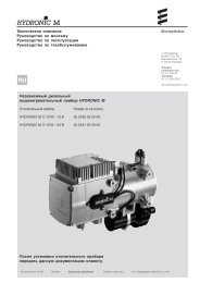
1 2345 6 78 91011161514131220SETPOINT35° FBOX TEMPERATUREALARM/FAULTiUNIT DATAFUNCTIONENTERAUTO START/STOPPRETRIPOOIROADCITYSPEEDM<strong>AND</strong>EFROSTBUZZER OFFST<strong>AND</strong>BYCAB COMM<strong>AND</strong>1. Muffler9. Compressor Pressure Regulating Valve (CPR)2. Thermal Expansion Valve (Location)10. Accumulator3. Engine (Refer toTable 1-1)11. Filter-Drier4. Heat Exchanger (Location)12. Receiver5. Compressor13. Hot Gas Bypass Solenoid (HGS2)6. Alternator14. Hot Gas Valve (Three-Way) (HGS1)7. Electric Standby Motor15. Condenser8. Defrost Air Switch16. Radiator Overflow ReservoirFigure 1-1. Condensing Section - Top View/Cab Command62--108281--2
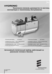
151. Fuel Filter2. Model/Serial Number Plate3. Speed and Run Solenoids2344. Oil Filter5. Air CleanerFigure 1-2. Unit Curbside View37124561. Receiver Sight Glasses2. Electrical Box (See Figure 1-4)3. Evaporator4 Relay/Fuse BoardFigure 1-3. Unit Roadside View5. Standby Board6. Manual Glow/Crank Switch (MGC -- If Equipped)7 RUN/STOP Switch (RSS)1--3 62--10828
123410596781. Manual RUN/STOP Switch2 Manual Glow/Crank Switch (If Equipped)3. Warning Buzzer4 Summer/Winter Switch (EWHS Only)5 Fuel Heater Relay (FHR -- Option)6. Main Fuse (F1, 80 amp)7. Relay/Fuse Board (See Table 1-9 &Figure 1-5)8. Motor Overload Relay (MOL)9. Standby Motor Contactor (MC)(Located in plug box on <strong>950</strong>)10.Microprocessor ModuleNote: See Figure 2-1 for Cab CommandFigure 1-4. Electrical Box62--108281--4
FHRFigure 1-5. Relay/Fuse Board (With All Optional Components)Table 1-3. Fuse IdentificationDesig. Item AmpsF1 Main Fuse (See Figure 1-1) 80AF2 RCR Fuse 5AF3 Run Relay Fuse 15AF4 Heat Relay Fuse 3AF5 Speed Relay Fuse 10AF6 Unloader Fuse (<strong>850</strong> & <strong>950</strong>) 5AF7 Defrost Damper Relay Fuse(Option) (<strong>950</strong> Only)15AF8 Electric Fan Motor Fuse 20AF9 Electric Fan Motor Fuse 20AF10 Electric Fan Motor Fuse 20AF11 Fuel Pump Fuse 5AF12 Fuel Heater Fuse (Option) 25ATable 1-4. Relay IdentificationDesig.ItemSSRStarter Solenoid RelayEFMR1 Electric Fan Motor RelayEFMR2 Electric Fan Motor RelayEFMR3 Electric Fan Motor RelayDDR Defrost Damper Solenoid Relay (Option)UFR Unloader Front Relay (<strong>850</strong> & <strong>950</strong>)CCRCompressor Clutch RelaySRSpeed RelayHR1 Heat Relay 1DERDiesel Electric RelayRRRun RelayGPRGlow Plug RelayRCRRun Control RelayEHREvaporator Heater RelayFHR Fuel Heater Relay (Optional)1--5 62--10828
Test Point #TP1TP2TP3TP4TP5TP6TP7TP8TP9TP10TP11TP12TP13TP14TP15TP16TP17Table 1-5.Test Point IdentificationCircuitRR NO OutputDER NC OutputF11 OutputDER NO OutputEHR NO OutputSSR NO OutputGPR NO OutputHR1 NO OutputSR NO OutputUFR NO OutputCCR NO OutputDDR NO OutputEFMR1 NO OutputEFMR2 NO OutputEFMR3 NO OutputRCR NO OutputDPS 12 Volt Input1.2 GENERAL DESCRIPTIONThe <strong>Supra</strong> models are self contained one-piece refrigeration/heatingunits designed for truck applications.The units consist of a condenser section, located outsidethe truck body, and an evaporator section whichextends inside the body. Two types of drives may beincluded:Road OperationBoth the TDB and TDS model units are equipped with anengine. In the Road Operation mode, the compressorand alternator are driven by the engine. TDB units do nothave standby motors. A standby motor shell is installed(without the motor winding) to allow the same belt arrangementfor both units.Standby OperationTDS units are equipped with an internal combustiondiesel engine and an electric standby motor. In StandbyOperation, the compressor and alternator are driven bythe electric standby motor.1.3 CONDENSING SECTIONThe condensing section (see Figure 1-1, Figure 1-2 &Figure 1-3) contains the drive equipment, alternator andthe high side refrigeration system equipment. The engineradiator and refrigerant condenser are incorporatedinto a single condenser/radiator assembly.1.3.1 Drive EquipmentThe drive equipment includes the engine, enginemounted clutch, air cleaner, muffler, coolant overflowbottle, drive belts and standby motor.a. EngineThe engine (Figure 1-1, item 3) is a TriVortex dieselmanufactured by Kubota. Engine operation is controlledby a Run Solenoid and a Speed Solenoid. The engine iscooled by a radiator which is integral with the refrigerantcondenser. The cooling system is fitted with a coolantoverflow reservoir. Engine air cleaners are dry type.b. Clutch AssemblyThe clutch assembly is mounted on the engine crankshaft.All units have centrifugal type clutches.c. Standby MotorThe standby motor operates on nominal460v-3ph-60Hz or 230v-3ph-60Hz power. An overloadand short cycle protection is provided along with automaticreset. Units are also equipped with a remotemounted power receptacle.d. Alternator/RegulatorCAUTIONObserve proper polarity when installingbattery, negative battery terminal must begrounded. Reverse polarity will destroy therectifier diodes in alternator. As a precautionarymeasure, disconnect positive batteryterminal when charging battery in unit.Connecting charger in reverse will destroythe rectifier diodes in alternator.The alternator supplies power for operation of the systemcontrols, evaporator fan motors and for charging ofthe unit battery, if equipped.The alternator converts mechanical and magnetic energyto alternating current (AC) and voltage, by the rotationof an electromagnetic field (rotor) inside a threephase stator assembly. The alternating current and voltageis changed to direct current and voltage, by passingAC energy through a three phase, full-wave rectifiersystem. Six silicon rectifier diodes are used.The regulator is an all-electronic, transistorized device.No mechanical contacts or relays are used to performthe voltage regulation of the alternator system. Theelectronic circuitry should never require adjustment andthe solid state active elements used have proved reliableenough to warrant a sealed unit.The regulator is an electronic switching device. Itsenses the voltage appearing at the auxiliary terminal ofthe alternator and supplies the necessary field currentfor maintaining the system voltage at the output terminal.The output current is determined by the load.62--108281--6
123LB--41. Positive OutputTerminal2.3.Regulator12vdc Test LampTerminal4. Ground TerminalB+Figure 1-6. 70 Amp Alternator (P/N 30-60050-04)1.3.2 Condensing Section Refrigeration SystemThe condensing section mounted refrigeration systemequipment includes the compressor, condenser/subcooler,accumulator, defrost air switch, filter drier, receiver,hot gas (three way) valve, hot gas bypass valve(except for <strong>950</strong>) and compressor pressure regulatingvalve.a. CompressorThe compressor assembly includes the refrigerant compressor,suction and discharge service valves, highpressure switch, unloader(s) (<strong>850</strong> and <strong>950</strong> only) and thesuction pressure transducer. The compressor drawsrefrigerant gas from the evaporator and delivers it to thecondenser at an increased pressure. The pressure issuch that refrigerant heat can be absorbed by the surroundingair at ordinary temperatures.b. Compressor Unloader (<strong>850</strong> and <strong>950</strong> Only) (Referto Section 3.1.7 for detailed information on unloadertemperature control)The <strong>Supra</strong> <strong>850</strong> and <strong>950</strong> unit compressors are fitted withone electric unloader valve. The capacity controlled cylinderis easily identified by the solenoid which extendsfrom the side of the cylinder head. When the solenoid isenergized two cylinders are unloaded. The unloadedcylinders operate with little or no pressure differential,consuming very little power. A description of unloaderoperation is provided in the following steps.Unloaded OperationPressure from the discharge manifold (Figure 1-7, item15) passes through the strainer (9) and bleed orifice (8)to the back of the piston bypass valve (7). Unless bledaway, this pressure would tend to close the piston (6)against the piston spring (5) pressure.With the solenoid valve (1) energized the solenoid valvestem (2) will open the gas bypass port (3).Refrigerant pressure will be bled to the suction manifold(10) through the opened gas bypass port . A reduction inpressure on the piston bypass valve will take place becausethe rate of bleed through the gas bypass port isgreater than the rate of bleed through the bleed orifice(8).When the pressure behind the piston has been reducedsufficiently, the valve spring will force the piston bypassvalve back, opening the gas bypass from the dischargemanifold to the suction manifold.Discharge pressure in the discharge manifold will closethe discharge piston check valve assembly (14) isolatingthe compressor discharge manifold from the individualcylinder bank manifold.The unloaded cylinder bank will continue to operate fullyunloaded until the solenoid valve control device is de--energized and the gas bypass port is closed.12 38914151. Solenoid Valve2. Valve Stem3. Gas Bypass Port4. Spring Guide5. Spring6. Piston7. Piston Bypass Valve8. Bleed Orifice9. Strainer10.Suction Manifold45671110121311. Cylinder DischargeValve12. Valve Plate13. Cylinder SuctionValve14. Discharge PistonCheck ValveAssembly15. Discharge ManifoldFigure 1-7. Cylinder Head - Unloaded1--7 62--10828
Loaded OperationDischarge pressure bleeds from the discharge manifold(Figure 1-8, item 15) through the strainer (9) and (8)bleed orifice to the solenoid valve stem (2) chamber andthe back of the piston bypass valve (7).With the solenoid valve (1) de-energized the solenoidvalve stem will close the gas bypass port (3).Refrigerant pressure will overcome the bypass valvespring (5) tension and force the piston (6) forward closingthe gas bypass from the discharge manifold to thesuction manifold (10).Cylinder discharge pressure will force open the dischargepiston check valve assembly (14). Refrigerantgas will pass into the compressor discharge manifold.The loaded cylinder bank will continue to operate fullyloaded until the solenoid valve control device is energizedand the gas bypass port is opened.2 3456711c. Condenser/SubcoolerThe condenser is of the tube and fin type and acts as aheat exchanger in which the compressed refrigerantgas is condensed into a liquid and lowered in temperature.Air movement over the condenser is provided by afan mounted on the standby motor/motor shell shaft.A portion of the condenser is occupied by the subcooler.Refrigerant leaving the receiver is passed through thesubcooler where additional heat is removed. Removalof this additional heat helps to ensure that only liquidrefrigerant enters the thermal expansion valve.d. AccumulatorThe accumulator is a refrigerant holding tank located inthe suction line between the evaporator and compressor.The purpose of the accumulator is to prevent entryof any liquid refrigerant into the compressor.Refrigerant vapor leaves the accumulator outlet pipe at apoint well above any liquid level thus preventing the entranceof liquid. The outlet pipe is equipped with an orificethat controls oil return to the compressor and preventsaccumulation of oil within the tank.198101213FromevaporatorTo compressor suction1415Oil return orifice1. Solenoid Valve2. Valve Stem3. Gas Bypass Port4. Spring Guide5. Spring6. Piston7. Piston Bypass Valve8. Bleed Orifice9. Strainer10.Suction Manifold11. Cylinder DischargeValve12. Valve Plate13. Cylinder SuctionValve14. Discharge PistonCheck ValveAssembly15. Discharge ManifoldFigure 1-9 Accumulatore. Compressor Pressure Regulating Valve (CPR)This adjustable regulating valve regulates the suctionpressure entering the compressor. The suction pressureis controlled to avoid overloading the electric motoror engine during high box temperature operation.Figure 1-8. Cylinder Head - Loaded62--108281--8
f. Hot Gas Solenoid Valve (Three-Way Valve)The Hot Gas Valve (HGS1) directs flow of refrigerantthrough the system. With the solenoid coil de-energizedthe valve is in the cool mode and the compressor dischargegas is delivered to the condenser. In the coolmode, heat is removed from the air inside the truck bodyand rejected to the surrounding air. With the solenoidcoil energized the valve is in the heat mode and thecompressor discharge gas is diverted to the evaporator.In the heat mode, heat is removed from the air surroundingthe truck body and rejected to the air inside the truckbody. A description of valve operation is provided in thefollowing sub-paragraphs.Cooling Operation(See Figure 1-10.)With the solenoid coil de-energized the valve is in thecool operating mode and the refrigerant gas is divertedto the condenser. The volume directly above the pistonassembly is open to suction pressure through the externalpilot connection and the volume underneath the pistonassembly is open to discharge pressure through thecompressor discharge connection. This difference inpressure across the piston assembly results in the pistonassembly being shifted upward, shutting the heatand defrost port, opening the condenser port, and allowingrefrigerant to flow to the condenser.TO COMPRESSORSUCTIONHeat and Defrost Operation (See Figure 1-11.)When the hot gas solenoid coil is energized, dischargegas flows to the evaporator for heating or defrost. Whenenergized, the solenoid plunger is lifted, allowing dischargegas to fill the volume above the piston assembly.Discharge gas is also allowed to fill the volume below thepiston assembly through the compressor dischargeconnection. The pressure on both sides of the pistonassembly is now equal and the piston spring exerts aforce on top of the piston assembly and shifts it downward.The condenser port is now closed and the evaporatorport is open. In both the energized and de-energizedpositions, the bypass of discharge gas to the suctionport is prevented.SolenoidenergizedTo evaporatorFromcompressorSOLENOIDDE-ENERGIZEDTO EVAPORATORFROMCOMPRESSORFigure 1-11. Hot Gas Valve - Heat and DefrostFlowg. Hot Gas Bypass Solenoid Valve (except <strong>950</strong>)The hot gas bypass solenoid valve (HGS2) opens duringheating and allows the compressor to draw vaporfrom the top of the receiver resulting in increased heatingcapacity.TO CONDENSERFigure 1-10. Hot Gas Valve - Cooling Flow1--9 62--10828
h. Filter DrierThe drier is cylinder shell containing a drying agent andscreen. It is installed in the liquid line and functions tokeep the system clean and remove moisture from therefrigerant. A sight glass may also be installed downstreamof the drier. The sight glass is fitted with a paperelement that changes color to indicate moisture content.i. ReceiverLiquid refrigerant from the condenser drains into thereceiver. The receiver serves as a liquid reservoir whenthere are surges due to load changes in the system; as astorage space when pumping down the system and as aliquid seal against the entrance of refrigerant gas intothe liquid line.The receiver is provided with two bullseye sight glasses,for the observation of liquid level, and a pressure reliefvalve.1.4 EVAPORATOR SECTIONThe evaporator section contains the evaporator coil,expansion valve (TXV), heat exchanger, defrost terminationthermostat(s) and electrical evaporator fanmotors.1.4.1 Thermal Expansion ValveThe thermal expansion valve is an automatic devicewhich controls the flow of liquid to the evaporator accordingto changes in superheat to the refrigerant leavingthe evaporator. The thermal expansion valve maintainsa relatively constant degree of superheat in the gasleaving the evaporator regardless of suction pressure.Thus, the valve has a dual function; automatic expansioncontrol and prevention of liquid return to the compressor.1.4.2 Heat ExchangerThe heat exchanger is of the tube in tube type connectedin the main suction line and liquid line. Within theheat exchanger, the cold suction gas is used to cool thewarm liquid refrigerant. This results in greater systemcapacity and efficiency.1.4.3 Evaporator CoilThe evaporator coil is a tube and fin type. The operationof the compressor maintains a reduced pressure withthe the coil. At this reduced pressure, the liquid refrigerantevaporates at a temperature sufficiently low enoughto absorb heat from the air. Air movement over thecondenser is provided by two or three electric fans.1.4.4 Electric and Water HeatThe unit can be equipped with Electric Heat, WaterHeat, and Electric/Water heat. See Figure 1-12. Whenthe controller calls for heat, the heater contactor willclose or valve will open and engage the heat system.Water Heat Coil2ElectricHeatElementsELECTRIC HEAT CONTROL BOX341UNIT CONTROL BOXHOT WATER HEAT COMPONENTS1. Water Valve2. Water Tube (HWH)3. Hose (HWH)4. Harness (HWH)Figure 1-12. Water and Electric Heat Components62--108281--10
1.5 SYSTEM OPERATING CONTROLS <strong>AND</strong>COMPONENTSThe unit is furnished with a microprocessor controlsystem. Once the set point is entered at the controller,the unit will operate automatically to maintain the desiredtemperature within very close limits. The controlsystem automatically selects high and low speed coolingor high and low speed heating as necessary to maintainthe desired temperature.Units also have a auto start/stop feature. Auto start/stopoperation provides automatic cycling of the diesel engineor standby motor, which in turn offers an energyefficient alternative to continuous operation.1.5.1 Switches And ControlsManual control switches are located on the side of theelectrical box. Components required for monitoring andcontrolling the diesel engine and refrigeration systemare located on the engine, compressor or system piping.1. RUN/STOP Switch (RSS)This switch controls the supply of power to the microprocessorand cab command. The switch is placed in theON position to allow manual or automatic unit operation.With the switch in the OFF position, the unit will be shutdown and neither manual or automatic starting is allowed.2. Manual Glow/Crank Switch (MGC) If EquippedIf the unit is equipped with a Manual Glow/Crank Switch,it is a three--position switch. This switch is held in theGLOW position to energize the glow plugs and pre-heatthe combustion chamber. The switch is moved to theCRANK position to manually engage the engine starter.When the switch is released, it returns to the middleposition to de-energize both components.3. Oil Pressure Safety Switch (OP)This switch will automatically stop the engine upon lossof oil pressure. The switch is located on the side of theengine.4. Water Temperature Sensor (WTS)The microprocessor will stop the unit when this sensorsignals a high water temperature condition. The sensoris located on the engine cylinder head.5. High Pressure Cutout Switch (HP1)This switch will automatically stop the engine whencompressor discharge pressure exceeds the set point.The switch is located on the compressor cylinder head.6. High Pressure Cutout Switch (HP2) (<strong>850</strong> Only)This switch is used to unload the compressor in highambient conditions.7. Compressor Discharge Temperature Sensor (CDT)(except for <strong>850</strong>)The microprocessor will stop the unit when this sensorsignals a high discharge temperature condition. Thesensor is located on the compressor center head.8. Compressor Suction Pressure Transducer (SPT)The Compressor Suction Pressure Transducer signal isused by the microprocessor in the compressor protectionlogic to protect the compressor under excessivesuction pressure conditions and under excessively lowsuction pressure conditions. The sensor is located onthe compressor body for all units except <strong>850</strong>. It is locatedin the suction line for <strong>850</strong> units.9. Ambient Temperature Sensor (ATS) (<strong>950</strong> Only)The Ambient Temperature Sensor signal is used by themicroprocessor in the compressor protection logic todetermine expected conditions. It is located betweenthe condenser and the front grille.10. Temperature control sensorsBox temperature is controlled by one or two sensors:SRAS: Measures return air to the evaporatorSSAS (optional): Measures supply air to the evaporatorand is also used in heat option kits as an overtemperaturesafety sensor.1--11 62--10828
1.6 UNIT SPECIFICATIONS1.6.1 Engine DataLubrication SystemLube Oil Viscosity: (API Classification CD)Outdoor TemperatureSAE Delvac 1Fahrenheit CentigradeBelow 32_ Below 0_C 10W or 10W3032_ to 77_F 0_ to 25_C 20WOver 77_F Over +25_C 30W or 15W4015W40Engine ModelDisplacementTable 1-6 Engine Data For <strong>Supra</strong> <strong>550</strong>CT2-29TV (Z482)29.2 in 3 (479 cc)No. Cylinders 2HorsepowerWeightCoolant CapacityOil CapacityOperatingSpeedsInjection SettingHighLowOil Pressure SwitchGlow PlugFuel Heater Thermostat8.5 hp (6.3 kW) @2400rpm117lbs(53kg)4.0 quarts (3.8 liters) Without EWHS4.5 quarts (4.3 liters) -- With EWHSUse 50/50 to 60/40 ethylene glycol/water mix, standard or Shell Dexcool extendedlife antifreeze6.0 quarts (5.7 liters) -- Without Bypass7.0 quarts (6.6 liters) -- With Bypass2300 -- 2350 rpm1800 to 1<strong>850</strong> rpm1991 to 2133 psig (135 to 145 Bars)Closes at: 18 ¦ 3psig(1.2¦ 0.2 Bar)0.9 ohms at 11 volts.Closes on temperature falls at 45+ 6.5_F (7.2¦ 1.17° C)Opens on temperature rise at: 75¦ 6.5_F (24¦1.17° C)62--108281--12
Table 1-7 Engine Data For <strong>Supra</strong> <strong>650</strong>/<strong>750</strong>/<strong>850</strong>Engine ModelDisplacementCT3-44TV43.9 in 3( 719 cc)No. Cylinders 3HorsepowerWeightCoolant CapacityOil CapacityOperatingSpeedsHighLowInjection SettingOil PressureSwitchGlow PlugFuel Heater Thermostat15.5 hp (11.6 kW ) @2400rpm139 lbs (63 kg)3.9 quarts (3.7 liters ) - Without EWHS4.5 quarts (4.3 liters) - With EWHSUse 50/50 to 60/40 ethylene glycol/water mix, standard or extended life antifreeze7.8 U.S. quarts (7.4 liters) -- Without Bypass8.8 U.S. quarts (8.3 liters) -- With Bypass<strong>650</strong>: 2200 to 2250 rpm<strong>750</strong> Prior to Serial Number KFW90913748; 2200 -- 2250.Beginning with Serial Number KFW90913748; 2400 -- 2450<strong>850</strong>: 2300 to 2350 rpm1800 to 1<strong>850</strong> rpm1991 to 2133 psi (135 to 145 Bars)Closes at: 18 +/-- 3 psig (1.22 +/-- 0.2 Bar)1.4 ohms at 11 volts.Closes on temperature falls at 45 +/-- 6.5_F (7.2+/--1.17° C)Opens on temperature rise at: 75 +/-- 6.5_F (24 +/--1.17° C)Engine ModelDisplacementTable 1-8 Engine Data For <strong>Supra</strong> <strong>950</strong>CT3-69TV (D1105)68.5 in 3 (1123 cc)No. Cylinders 3HorsepowerWeightCoolant CapacityOil CapacityOperating HighSpeeds LowInjection SettingOil PressureSwitchGlow PlugFuel HeaterThermostat20hp (14.9kW) @ 2400rpm214 lbs (97 kg)4.5 quarts (4.3 liters)Use 50/50 to 60/40 ethylene glycol/water mix, standard or extended life antifreeze10 quarts (9.46 liters)2200 to 2250 rpm1800 to 1<strong>850</strong> rpm1991 to 2133 psi (135 to 145 Bars)Closesat:18+/--3psig(1.2+/--0.2Bar)0.9 ohms at 11 volts.Closes on temperature falls at 45 +/-- 6.5_F (7.2+/--1.17° C)Opens on temperature rise at: 75 +/-- 6.5_F (24 +/--1.17° C)1--13 62--10828
1.6.2 Compressor DataModel (Unit) 05K 012 (<strong>550</strong>/<strong>650</strong>/<strong>750</strong>) 05K 024 (<strong>850</strong>) 05G37 (<strong>950</strong>)Displacement 12.2 in 3( 200 cc) 24.4 in 3 (400 cc) 37 in 3 (600 cc)No. Cylinders 2 4 6No. Unloaders 0 1 1Weight 84 lbs (38 kg) 108 lbs (49 kg) 137lbs (62 kg)Oil Charge 4.0 pints (1.9 L) 5.5 pts (2.6 L) 6.75 pts (3.2)RefrigerantR-404AAPPROVED COMPRESSOR OIL05G/05KMobile Arctic EAL 68Castrol Icematic SW-68Ca. High Pressure Cutout SwitchesHP1Cutout at: 465 +/-- 10 psig (32.7 +/-- 0.7 kg/cm@)Cut-in at: 350 +/-- 10 psig (24.6 +/-- 0.7 kg/cm@)HP2 <strong>850</strong> OnlyCutout at: 367 +/-- 12 psig (25 +/-- 0.8 kg/cm@)Cut-in at: 440 +/-- 10 psig (29.9 +/-- 0.7 kg/cm@)b. Compressor Discharge Temperature Sensor(CDT)This is a thermistor type sensor located (when installed)on the compressor discharge cover.Unit shuts down:SIf ambient is less than 120°F (50°C) <strong>AND</strong>Temperature exceeds 310°F (154°C) for 3 minSIf ambient is greater than 120°F (50°C) <strong>AND</strong>Temperature exceeds 340°F (171°C) for 3 minSImmediately shuts down in all ambientsIf temperature exceeds 350°F (177°C)1.6.3 Refrigeration System Dataa. Defrost Timer1-1/2, 3, 6, or 12 hoursb. Defrost ThermostatOpens at: 47_ +/-- 5_F (8_ +/-- 3_C)Closes at: 37_ +/-- 5_F (3_ +/-- 3_C)c. Defrost Air Switch Setting<strong>550</strong>/<strong>650</strong>/<strong>750</strong>; Initiates at: 1.00 +/-- .07 inch(25.4 ¦ 1.8 mm) wg<strong>850</strong>/<strong>950</strong>; Initiates at: 0.70 +/-- .07 inch(17.8 +/-- 1.8 mm) wgd. Refrigerant ChargeRefertoTable1-1e. Compressor Pressure Regulating Valve (CPR)MODELCPR Setting CPR SettingpsigBarsSUPRA <strong>550</strong> 34 +/-- 1 2.3 +/-- 0.07SUPRA <strong>650</strong> 28 +/-- 1 1.91 +/-- 0.07SUPRA <strong>750</strong> 32 +/-- 1 2.18 +/-- 0.07SUPRA <strong>850</strong>/<strong>950</strong> 29 +/-- 1 1.97 +/-- 0.07f. Thermostatic Expansion Valve SuperheatSetting at 0_F (--17.8_C) box temperature: 8-10_F(--13.3 to --12.2_C)62--108281--14
1.6.4 Electrical Dataa. Evaporator Fan MotorsBearing Lubrication: Factory lubricated, additionalgrease not requiredHorsepower0.13hp (100W)OperatingCurrent10.8 ampsSpeed2800 to3000 rpmVoltage12 vdcb. Standby MotorsBearing Lubrication: Factory lubricated additional grease not requiredRotation Speed: 1760 rpm@ 60Hz/1500 rpm@ 50HzVoltagePowerConnection Type3ph, 60 HzHPFull Load AmpsSUPRA <strong>550</strong>230 ∆207.6460 Y 14SUPRA <strong>650</strong>/<strong>750</strong>230 ∆237.6460 Y 13SUPRA <strong>850</strong>230 ∆19.68.3460 Y 9.8SUPRA <strong>950</strong>230 ∆328.3460 Y 23c. Alternator: 70 ampsd. Standby Motor OverloadMODELSETTING230V, 3 ph, 60 Hz 460V, 3 ph, 60 Hz<strong>550</strong> 16 AMPS --<strong>650</strong>/<strong>750</strong> 20 AMPS 10 AMPS<strong>850</strong> 21 AMPS 11 AMPS<strong>950</strong> 35 AMPS 23 AMPS1.6.5 TORQUE VALUESAssembly ft-lb NmPower Tray to Frame 40 54.2Standby Motor to Power Tray 22-28 30-44Engine to Power Tray 50 67.8Compressor to Power Tray 45-55 61-75Standby Motor Pulley 175inlbs19.8Engine Pulley 22 29.8Compressor Pulley 22 29.8Evaporator Fan Motor 13 17.6Evaporator Fan Grille 7 9.5Condenser Coil to Chassis 7 9.5Tensioner to Power Tray 22 29.8Engine Support 40 54.2Run & Speed Solenoids 7 9.5Condenser Fan Blade 18 24.4Engine Clutch 40 54.2Suction Service Valve 22-25 30-341--15 62--10828
1.7 SAFETY DEVICESSystem components are protected from damage caused by unsafe operating conditions by automatically shuttingdown the unit when such conditions occur. This is accomplished by the safety devices listed in Table 1-9.Table 1-9. Safety Devices - Microprocessor ControllerUnsafe Conditions Safety Device Device Setting1. Low engine lubricating oilpressureOil pressure safety switch (OP)automatic reset2. High engine coolant temperature Water temperature sensor(microprocessor)3. Excessive current draw by glowplug circuit, control circuit or startersolenoid (SS)4. Excessive current draw byrun control relay.5. Excessive current draw byrun relayFuse (F1)Fuse (F2)Fuse (F3)Opens below 18 ¦ 3 psig(1.2 ¦ 0.2 Bar)Opens above 230 ¦ 5_F(110 ¦ 3_C)Opens at 80 ampsOpens at 5 ampsOpens at 15 amps6. Excessive current draw heat relay Fuse (F4) Opens at 5 amps7. Excessive current draw by speedrelay7. Excessive current draw by unloader8. Excessive current draw bydefrost damper relay8. Excessive current draw byevaporator fan motors9. Excessive current draw by fuelpump10. Excessive compressordischarge pressure11. Excessive compressordischarge temperature12. Excessive current draw by fuelheater circuit (option)Fuse (F5)Fuse (F6) (<strong>850</strong> and <strong>950</strong> Only)Fuse (F7) (<strong>950</strong> Only)Fuse (F8, F9, F10)Fuse (F11)High pressure cutout switch (HP) automaticresetCompressor dischargetemperature sensor (CDT)Fuse (F12)Opens at 10 ampsOpens at 5 ampsOpens at 15 ampsOpens at 20 ampsOpens at 5 ampsRefer to Section 1.6.3.a.Shuts unit down above310_F (154_C) for 3 minutesor 350_F (177_C)Opens at 25 amps62--108281--16
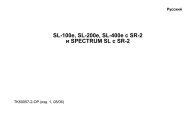
1.8 REFRIGERANT CIRCUIT1.8.1 Cooling (See Figure 1-13)When cooling, the unit operates as a vapor compressionrefrigeration system. The main components of the systemare the reciprocating compressor, air-cooled condenser,thermostatic expansion valve, direct expansion evaporator,and hot gas valve.In the cooling mode, the hot gas valve is de-energized.With the hot gas valve de-energized, flow through thevalve is from the side discharge connection to the bottomcondenser connection.The compressor raises the pressure and temperature ofthe refrigerant and forces it into the condenser tubes.The condenser fan circulates surrounding air over theoutside of the condenser tubes. Heat transfer is thusestablished from the refrigerant gas (inside the tubes) tothe condenser air (flowing over the tubes). The condensertubes have fins designed to improve the transferof heat. This removal of heat causes the refrigerant toliquefy; liquid refrigerant flows from the condenser and,except for the <strong>950</strong>, through a check valve to the receiver.The receiver stores the additional charge necessary forlow ambient operation and for heating and defrost modes.The refrigerant leaves the receiver and flows through amanual receiver shutoff valve (king valve) to the subcooler.The subcooler occupies a portion of the maincondensing coil surface and gives off further heat to thepassing air.The refrigerant then flows through a filter-drier where anabsorbent keeps the refrigerant clean and dry.The refrigerant then flows to the “Liquid/suction” heatexchanger. Here the liquid is further reduced in temperatureby giving off some of its heat to the suction gas.The liquid then flows to an externally equalized thermostaticexpansion valve (TXV) which reduces the pressureof the liquid and meters the flow of liquid refrigerantto the evaporator to obtain maximum use of the evaporatorheat transfer surface.The evaporator tubes have aluminum fins to increaseheat transfer; therefore heat is removed from the aircirculated through the evaporator. This cold air is circulatedthroughout the truck to maintain the cargo at thedesired temperature.The transfer of heat from the air to the low temperatureliquid refrigerant causes the liquid to vaporize.This low temperature, low pressure vapor passesthrough the “suction line/liquid line” heat exchangerwhere it absorbs more heat from the high pressure/hightemperature liquid and then returns to the accumulator.The compressor draws this vapor out of the accumulatorthrough a pick-up tube which is equipped with ametering orifice. This orifice prevents the accumulationof oil in the accumulator tank. The metering orifice iscalibrated to control the rate of oil flowing back to thecompressor.The vapor refrigerant then enters the compressor pressureregulating valve (CPR) which regulates refrigerantpressure entering the compressor, where the cyclestarts over.1.8.2 Heat And Defrost (See Figure 1-13)When refrigerant vapor is compressed to a high pressureand temperature in a reciprocating compressor,the mechanical energy necessary to operate the compressoris transferred to the gas as it is being compressed.This energy is referred to as the “heat of compression”and is used as the source of heat during theheating cycle.When the controller calls for heating or defrost, the hotgas valve solenoid energizes, closing the port to thecondenser and opening a port which allows heated refrigerantvapor to flow through the drainpan heater tubeto the evaporator coil.The hot gas bypass solenoid valve (not on <strong>950</strong>) alsoopens during heating to provide additional refrigerant tothe compressor from the receiver. This increases theamount of refrigerant in circulation, increasing heatingcapacity.The main difference between heating and defrosting isthat, when in heating all the evaporator fans continue torun, blowing the air over the heated coils to heat theproduct. When defrosting, the evaporator fans stop,allowing the heated vapor to defrost any ice build upthere maybe.The bypass line draws refrigerant from the receiver andinjects it through a metered valve into the suction linepast the compressor pressure regulator valve. This willraise the discharge pressure and temperature.1--17 62--10828
EVAPORATORFILTER DRIERTXVBULBDRAIN PAN HEATERTXVCHECKVALVE**HOT GASBYPASSSOLENOIDVALVE(HGS2)**RECEIVER VALVEINLETCHECKVALVERECEIVERHEATEXCHANGERHOT GASVALVE (HGS1)SUBCOOLERCOMPRESSORPRESSUREREGULATORVALVEDISCHARGE<strong>SERVICE</strong>VALVEHP2*HPSPTCONDENSERMETERINGORIFICEACCUMULATORCOMPRESSORSUCTION<strong>SERVICE</strong>VALVECOOLING CYCLE* <strong>850</strong> ONLY**<strong>550</strong>/<strong>650</strong>/<strong>750</strong>/<strong>850</strong> ONLYDischargeLiquidSuctionInactiveEVAPORATORFILTER DRIERTXVBULBDRAIN PAN HEATERTXVCHECKVALVE**HOT GASBYPASSSOLENOIDVALVE(HGS2)**RECEIVER VALVEINLETCHECKVALVERECEIVERHEATEXCHANGERHOT GASVALVESUBCOOLERCOMPRESSORPRESSUREREGULATORVALVEDISCHARGE<strong>SERVICE</strong>VALVEHP2*HPSPTCONDENSERMETERINGORIFICEACCUMULATORCOMPRESSORSUCTION<strong>SERVICE</strong>VALVEHEAT <strong>AND</strong> DEFROST CYCLE* <strong>850</strong> ONLY**<strong>550</strong>/<strong>650</strong>/<strong>750</strong>/<strong>850</strong> ONLYDischargeLiquidSuctionInactiveFigure 1-13. Refrigeration Circuit62--108281--18
SECTION 2<strong>OPERATION</strong>2.1 MICROPROCESSOR CONTROLLER2.1.1 IntroductionCAUTIONUnder no circumstances should anyone attemptto repair the Logic or Display Boards.Should a problem develop with these components,contact your nearest Carrier Transicolddealer for replacement.The Microprocessor System consists of the microprocessormodule (Item 10, Figure 1-4), relay/fuse board(Item 7, Figure 1-4), Cab Command Figure 2-1 and interconnectingwiring.a. The Microprocessor Module includes the temperaturecontrol software and necessary input/output circuitryto interface with the unit controls.b. The Relay Board contains replaceable relays, diodesand fuses.c. The Cab Command is remote mounted in the truck.The Cab Command includes the LCD display andkeypad. The keypad and display serve to provideuser access and readouts of microprocessor information.The information is accessed by keypadselections and viewed on the display.The Carrier Transicold Microprocessor System incorporatesthe following features:a. Control supply or return air temperature to tight limitsby providing refrigeration control, heat and defrost toensure conditioned air delivery to the load.b. Default independent readouts of set point (at the leftof the display) and actual supply or return air temperature(at the right).c. Digital readout of unit data points such as pressures,temperatures and other microprocessor inputs.d. Digital readout of selectable operating parameters(Function Codes) and the ability to change those settings.e. Digital display of Alarm Indications.f. A self-test check on program memory and datamemory at start-up.121314151617181920-20 35° FSETPOINT BOX TEMPERATUREFUNCTIONENTERALARM/FAULTiUNIT DATAAUTO START/STOP123PRETRIPOI4ROADCITYSPEEDM<strong>AND</strong>EFROSTBUZZEROFFST<strong>AND</strong>BY1110987651. Unit Data Key2. Auto Start/Stop -Continuous Run Key3. Pretrip Key4. Stand-by Key5. Buzzer Off Key6. Enter Key7. Manual Defrost Key8. City Speed Key9. Road Key10. Function Key11. I/O Switch12. Cool Mode13. Heat ModeFigure 2-1. Cab Command14. Defrost Mode15 Road Mode16. Auto Start/Stop Mode17. Stand-by Mode18. City Speed Mode19. Out-of-range20. Fault Light2--1 62--10828
g. A Pre-Trip checkout of refrigeration unit operation.h. An optional RS232 communication port to communicateunit operating data to a mobile satellite transmitter.This information will then be relayed back to theoffice via a modem to a computer.There are presently three (3) protocols supported.The protocol for the QualComm transmitter, the protocolfor the HUGHES transmitter, and the CarrierCommunication Protocol. The microprocessor willtransmit a HUGHES protocol packet every hour.Transmission with the Carrier or QualComm protocolis by request.2.2 MICROPROCESSOR CONFIGURATIONThe microprocessor is configured in accordance withthe equipment supplied on an individual unit and therequirements of the original purchase order. The configurationsdo not require change unless the unit has anequipment change or a change is required by the owner.Although the configurations may not be modified usingthe keypad, operational differences will be notedthroughout the following descriptions and operating procedures.See NO TAG for list of microprocessor configurations.Some microprocessor settings such as setpoint andfunctional parameters may be changed at the keypadand are described in the following sections.2.3 DESCRIPTION OF MICROPROCESSORCOMPONENTS2.3.1 KeypadThe keypad (Figure 2-1) has 12 keys which allow theoperator to initiate various functions, display operatingdata and change operating parameters.Arrow KeysThe up and down ARROW keys are usedto modify (increment or decrement) thedisplayed data. If the unit is in the defaultdisplay these keys are pressed to change the setpointselection.Enter KeyThe ENTER key is used to accept achange in function codes or a change insetpoint.Manual Defrost KeyThe <strong>MANUAL</strong> DEFROST key is used toinitiate a defrost cycle. If the predeterminedconditions for defrost are not met,the unit will not enter defrost and the displaywill return to the default screen.Pretrip Check KeyThe PRETRIP keyisusedtoinitiateapretriptest cycle. If the predetermined conditionsfor pretrip are not met, the unit will notenter pretrip and the display will return tothe default screen.Auto Start/Stop - Auto Start/Continuous Run KeyThe AUTO START/STOP key is used tochange the operating mode from “ContinuousRun” to “Auto Start/Stop.” Each pushof the key will alternate the operating modes. The microprocessorretains the last entered setpoint in memoryeven if the unit is shut down or a power failure occures.The Auto Start/Stop indicator on the display will illuminatewhen Auto Stop/Start is enabled. If the indicator isnot illuminated, the unit is in the Continuous Run Mode.To start the unit in manual start mode, the auto start/-stop-continuous selection must be in continuous runmode and the Auto/Manual Start Operation functionparameter set to “MAN OP” (FN10 OFF)NOTEWhen configuration CNF11 is “ON” and setpointis 32 to 42_ F(0to5.5_C) the unit is lockedinto continuous run. The AUTO START/STOPkey is disabled.Function Change KeyThe FUNCTION CHANGE key is used todisplay the function codes. Each time thiskey is pressed the display will advance tothe next code. This key, in conjunction with the ARROWand ENTER keys, will allow the user to change theFunction Parameters. See Section 2.4.10 for more detailedinformation.Unit Data KeyThe UNIT DATA key is used to display thei unit operating data. This key, in conjunctionwith the ARROW keys, will allow the user todisplay the unit’s operating data values (i.e, coolant temperature,battery voltage, etc.) See Section 2.4.11 formore detailed information.City Speed KeyThe CITY SPEED key enables the cityspeed mode of operation. In the city speedmode, the unit will operate in low speed.Each push of the key toggles the operating mode. Themicroprocessor retains the last entered setpoint inmemory even if the unit is shut down or a power failureoccures. The city speed indicator on the display willilluminate when the city speed mode is enabled.Buzzer Off KeyThe BUZZER OFF key will disable the cabcommand buzzer. When not disabled byuse of this key, the buzzer is activatedwhenever the alarm/fault indicator is illuminated. Thebuzzer off indicator on the display will illuminate whenthe buzzer is disabled.62--108282--2
Road KeyThe ROAD key selects the diesel engineoperating mode. The microprocessorretains the last entered setpoint in memoryeven if the unit is shut down or a powerfailure occures.NOTEWhen functional parameter “FN10” is set fortime start, the unit optional auto diesel restart isactive and the Road key will be flashing.Stand-by KeyThe ST<strong>AND</strong>-BY key selects the electricmotor operating mode. The microprocessorretains the last entered setpoint inmemory even if the unit is shut down or a power failureoccures. “NO POWER” will be displayed, if unit isswitched to standby and power is not available.2.3.2 Digital DisplayThe digital display (see Figure 2-1) has nine positions.The default display is setpoint on the left and actualsupply or return air temperature on the right. The readoutmay be set to read in Degrees F or Degrees C.The display also has symbol --type indicators for the followingmodes: Cool, Heat, Defrost, Road (diesel) Operation,Auto Start/Stop mode, Stand-By mode, City Speedmode and Out-Of-Range operation. The indicator is illuminatedto indicate the mode or condition is active.On each power-up, the microprocessor will perform aself test. Errors, if any, will be indicated on the display asan EER.# where “#” is a number corresponding to thenumber of the failed test.ERRORCAUSEERR.1 Processor failureERR.2 Check chip installation or ReplaceERR.3 microprocessor.ERR.4 orDisplayDisplay board to logic board communicationfailure.This can be caused by a defectiveribbon cable or ribbon cable notplugged in properly.2.4 <strong>OPERATION</strong>2.4.1 Pre-Trip Inspectiona. Pre-Trip Inspection - Before StartingBefore starting engine check the following points:1.Drain water and sediment from fuel tank sump. Thenfill tank with diesel fuel.2.Drain water from fuel filter separator (if applicable).3.Check radiator coolant level. Antifreeze should beadjusted for climate conditions, minimum 50/50 mixture,maximum 60/40 mixture.4.Check condenser/radiator coil for cleanliness.5.Check air cleaner and hoses.6.Check Defrost Air Switch and hoses.7.Check engine oil level.8.Check condition and tension of all belts.9.Check all fan and idler bearings.10.Check door latches and hinges.11. Check condition of condenser fan blades.12.Check battery fluid level (if applicable)13.Check battery cables and terminals14.Check evaporator coil for cleanliness.15.Check evaporator fan16.Check air chute (if applicable)17.Check bulkhead and return air screens (if applicable)18.Check defrost water drains19.Check glow plugsb. Pre-Trip Inspection - StartingStart the unit in continuous run. Refer to Sections 2.4.2or 2.4.4c. Pre-Trip Inspection - After StartingAfter starting engine check the following points:1. Check electric fuel pump.2. Check fuel lines and filters for leaks.3. Check oil lines and filters for leaks.4. Check coolant hoses for leaks.5. Check exhaust system for leaks.6. Check condenser and evaporator fans for proper airflow.7. Initiate Pre-Trip and monitor all operating modes.Check unloader operation (<strong>850</strong> and <strong>950</strong>).d. After operating unit 15 minutes or more:8. Check water temperature. Should be 160 to 175_F(72to80_C)9. Check refrigerant level. (Refer to section 4.7)10.Check compressor oil level. (Refer to section 4.9)11. Put unit into manual defrost and monitor. Allow unitto terminate defrost automatically.12 Change over to desired operating mode, enter setpoint and change functional parameters as requiredto match the requirements of the load.2--3 62--10828
2.4.2 Starting - Road OperationPlace the I/O Switch in the “I” position. If the unit hasbeen used previously in the standby mode, press theroad operation button. Under normal circumstances thisis all that is required to start the unit. The unit will thenperform a complete diagnostic check on the microprocessorcontroller, pre-heat for the required amount oftime based on the engine temperature and start automatically.2.4.3 Starting - Standby Motor DriveWARNINGMake sure the power plug is clean and drybefore connecting to any power source.Do not attempt to connect or remove powerplug or perform service and/or maintenancebefore ensuring the unit RUN/STOPSwitch is in the STOP position and the I/OSwitch is in the “O” position.a. Place the I/O (Cab Command) and unit RUN/ STOPSwitches in the ON position and press the ST<strong>AND</strong>-BY key. The microprocessor will perform a self-test(all display messages will appear in display window).Then setpoint and box temperature will be displayed.“NO POWER” will be displayed if unit is switched toST<strong>AND</strong>BY and power is not available.b. Enter Set Point and change Functional Parameters tomatch the requirements of the load.2.4.4 Manual Starta. To start a unit equipped with a Manual Glow/CrankSwitch, place the unit RUN/STOP Switch in the RUNposition and the I/O Switch (Cab Command) to “I”position.b. Manual operation will only function if unit is in ContinuousMode. If the AUTO START/STOP indicator onthe cab command is illuminated, press the AUTOSTART/STOP key to place the unit in continuous runmode (indicator will not be illuminated).c. Press the FUNCTION key until AUTO OP or MANOP appears on the display. If MAN OP appears, proceedto step d. If AUTO OP appears:1. Press the Enter key.2. Press the Up Or Down Arrow key to bring MANOP on the display.3. Press the Enter key. Toplacetheunitinthe<strong>MANUAL</strong> START mode.WARNINGUnder no circumstances should ether orany other starting aids be used to start engine.d. Use the <strong>MANUAL</strong> GLOW/CRANK Switch to start theunit. Refer to Table 2-1 for required glow times.Table 2-1. Manual Glow TimeEngine Coolant TemperatureGlow Time inSecondsLess than 32_F (0_C) 1533_F to50_F (1_C to10_C) 1051_F to77_F (11_C to25_C) 5Greater than 78_F (26_C) 0e. Enter Set Point and change Functional Parameters tomatch the requirements of the load.2.4.5 Pre-TripPre-Trip is a test sequence that the operator may initiateto check unit operation. During Pre-Trip, the microprocessoroperates the unit in variousmodes allowingevaluationof unit operation. If a failure occurs duringPre-Trip, the microprocessor will generate an alarm.The following steps detail the sequence:a. The unit is operated to bring box temperature below40_F (4.4_C).b. The operator presses the PRETRIP key. If the defrostthermostat (DTT) is closed, the microprocessor willdisplay “PPPP” and the test is started. If DTT is open,the test will end.c. After 30 seconds in high speed cool, unit cycles tolow speed loaded cool.d. After 30 seconds, unit cycles to low speed unloadedcool.e. After 30 seconds, unit cycles to low speed unloadedheat.f. After 30 seconds, unit cycles to low speed loadedheat.g. After 30 seconds, unit cycles to high speed heat anddisplays coolant temperature.h. After 30 seconds, unit cycles to high speed cool anddisplays the defrost interval selection for 30 seconds,then unit cycles to defrost if DTT is closed.i. After standard defrost cycle, Pre-Trip is terminatedand unit returns to normal operation.2.4.6 SetpointNOTEIf configuration CNF3 is “ON” maximum setpointis increased to 90_F.Setpoints of -22_F to+86_F (-30_C to+30_C) may beentered via the keypad.With the default screen showing on the display, the up ordown ARROW key may be pressed to bring the set pointto the desired reading. The display will flash to indicate thatthe reading being displayed is a non-entered value.Depress the ENTER key to activate the new setting.If the ENTER key is not pressed within five secondsafter the last key stroke, the display will revert to theprevious active setting. The microprocessor retains thelast entered setpoint in memory even if the unit is shutdown or a power failure occurs.62--108282--4
2.4.7 Start/Stop OperationAfter start up, observe the AUTO START/STOP indicator.If it is illuminated, the unit is in the Auto Start/Stopmode. If not, press the Auto Start/Stop key to toggle theunit into Auto Start/Stop mode.Automatic start/stop is provided to permitstarting/restarting of the diesel-driven compressor asrequired. This gives the microprocessor automaticcontrol of starting and stopping the diesel engine. Themain function of automatic start-stop is to turn off therefrigeration system near the setpoint to provide a fuelefficient temperature control system and then restartthe engine when needed. Start-Stop operation isnormally used for frozen loads.Enter Set Point and change Functional Parameters tomatch the requirements of the load.Whenever the unit starts in Auto Start-Stop, it will rununtil:SIt has run for the predetermined minimum run time.SThe engine coolant temperature is above 122°F(50°C)SThe box temperature is at setpoint.The controller will not shut off the engine if the batteryvoltage is not sufficient to restart it. Battery voltageabove approximately 13.4 volts is required forshutdown. This varies depending on ambient. Look atbattery voltage in data list to find out whether shutdownvoltage has been reached. If there is a “+” in front of thenumber, the voltage is enough to shutdown and restart.If only the number appears, the voltage is still too low forshutdown.The controller will restart the engine if any of thefollowing criteria have been met:SBox temperature has changed by +/-- 11°F(+/--6.1°C)for setpoints in the perishable range and +11° F(+6.1°C) for setpoints in the frozen range DURINGminimum off time.NOTEAuto Start-Stop operation may be tied to the setpointranges for frozen and perishable loads and the AUTOSTART/STOP key may be locked out.2.4.8 Continuous Run OperationAfter start up, observe the AUTO START/STOP indicator.If it is illuminated, the unit is in the Auto Start/Stopmode . If Continuous Run operation (unit will operatecontinuously after starting) is desired, press the AutoStart/Stop key to change the operation to ContinuousRun.In the Continuous Run mode, the diesel engine will runcontinuously providing constant air flow andtemperature control to the product. Continuous Runoperation is normally used for perishable loads.Continuous operation may be tied to the setpoint rangesfor frozen and perishable loads and the AUTOSTART/STOP key may be locked out.The unit will remain in low speed for 10 minutes afterengine start-up when the Continuous Run setpoint isbelow 10°F (-12°C).Enter Set Point and change Functional Parameters tomatch the requirements of the load.2.4.9 Defrost CycleDefrost is an independent cycle overriding cooling andheating functions to de-ice the evaporator as required.For manual initiation, check that the box temperature is40°F (4.4°C) or lower and press the <strong>MANUAL</strong> DE-FROST key.The microprocessor will displays “DF” on the right of thedisplay during defrost mode . The left display will continueto display the setpoint. Defrost may be terminated inany of three ways; timer initiation, air switch initiationand manually.Refer to Section 3.1.6 for a more detailed description ofthe defrost cycle.SBox temperature has moved away from setpoint by +/--3.6°F (2.0°C) AFTER minimum off time for setpoints inthe perishable range or +0.5°F (0.3°C) for setpoints inthe frozen range.SThe battery voltage drops below 12.2 VDC Refer toTable 2-2 for unit data).SThe engine coolant temperature drops below 34°F(1°C).To start the unit in manual start mode, the unit must be incontinuous run mode and the Auto/Manual Start Operationfunction parameter set to “MAN OP” (FN10 OFF)NOTEWhen configuration CNF11 is “ON” and setpointis 32 to 42_ F(0to5.5_C) the unit is lockedinto continuous run. The AUTO START/STOPkey is disabled.2--5 62--10828
2.4.10 Functional ParametersNOTEIf configuration CNF11 is “ON” functional parametersare locked out and the ability tochange functional parameters from keypad isdisabled.The Function Parameters control selected operatingfeatures of the unit. These parameters can be displayedby pressing the FUNCTION CHANGE key. When multiplechoices are available, the display will show the functiondescription on the left side with the correspondingfunction choice on the right side. The list can be scrolledthrough by pressing the FUNCTION CHANGE key or byusing the ARROW keys. With each FUNCTIONCHANGE key push, the list is advanced one. If theFUNCTION CHANGE key is pressed and held for onesecond, the list will scroll at a rate of one item every 0.5seconds. Once the end of the list is reached the list willscroll back to the first entry.With a function parameter displayed, the data choicecan be changed by pressing ENTER then pressing eitherthe up or down ARROW keys. The displayed choicewill then flash to indicate that the choice has not beenentered. Depress the ENTER key to activate the newchoice. The display will stop flashing to indicate that thechoice has been entered.If the new choice is not entered in 5 seconds, the displaywill revert back to the last entered choice. All functionparameters are retained in memory. Descriptions of thefunction parameters and operator choices are providedin the following paragraphs. A function parameter listingis also provided in Table 2-1.Defrost IntervalThe English display for Defrost Interval is “DEFR” thecode display is “FN0.” The choices are displayed withone decimal place and then the capital letter H for hours(i.e., DEFR 12.0H). The defrost choices are 1.5, 3, 6 or12 hours.Speed ControlThe Speed Control parameter overrides the normal microprocessorspeed control solenoid operation. ParameterEnglish displays are “CITY SPD” or “HIGH SPD.”The code displays are “FN1 ON” or “FN1 OFF.” With“CITY SPD” or “FN1 ON” displayed the unit is lockedinto low speed. With “HIGH SPD” or “FN1 OFF” displayed,speed is under normal microprocessor control.Minimum Off-TimeThe auto start mode Minimum Off-Time parameter Englishdisplay is “OFF T” the code display is “FN2.” Thechoice for the off-time is displayed with two digits andthen the capital letter M for minutes (i.e. OFF T 20M orFN2 20M). The off-time choices are 10, 20, 30, 45 or 90minutes.Minimum On-TimeThe auto start mode Minimum On-Time parameter Englishdisplay is “ON T.” The code display is “FN3.” Thechoice for the on-time is displayed with two digits andthen the capital letter M for minutes (i.e. ON T4 M).Theon-time choices are 1 or 4 minutes.Controlling ProbeThe Controlling Probe parameter English displays are“REM PROBE” or “SUP PROBE.” The code displaysare “FN4 A” or “FN4 B.” With “REM PROBE” or “FN4 A”displayed, the microprocessor is set for operation with asingle probe sensing return air temperature. With “SUPPROBE” or “FN4 B” displayed, the microprocessor isset for dual probe (supply air or return air) control.Standard Units SelectThe Standard Unit Select parameter allows selection ofEnglish or metric data display. The English display is DE-GREES F or C. The code display is FN5. The choicesare_C and _F. This parameter will also convert pressurereadings to psig or bars.Maximum Off TimeThe auto start mode Maximum Off Time English displayis “TIME START” or “TEMP START” the code display is“FN6 ON” or “FN6 OFF.” With “TIME START” or “FN6ON” displayed the engine will be started 30 minutesafter shutdown. With “TEMP START” or “FN6 OFF”displayed the engine will be under normal microprocessortemperature control.Diesel Backup Feature:If the unit is in standby mode and AC power is lost for fiveminutes or more, the diesel engine will start and run untilAC power is restored and applied for five minutes. TheROAD icon will blink once every second while the PLUGicon will stay on constantly to indicate that this feature isactive.When the five minute shutdown timer expires and ACpower is present, the unit will shut down the diesel engineand restart the standby motor. If AC power is NOTpresent, the diesel engine will operate.If the unit is set to “TEMP START” the standby dieselback up feature will be turned off and the unit will operatein normal standby mode.MOP STD - Future ExpansionUsed to add or subtract 5psig (0.34 Bar) to unloaderequations. English display is “MOP STD.” The codedisplayis“FN7”Compartment 2 Setpoint - N/AEnglish display is “2SET.” The code display is “FN8”Compartment 3 Setpoint - N/AEnglish display is “3SET.” The code display is “FN9”Auto/Manual Start OperationThe English displays for Auto/Manual Start Operationare “AUTO OP” and “MAN OP.” The code displays are“FN10 ON” and “FN10 OFF.” With “AUTO OP” or “FN10ON” displayed the unit will be in the Auto Start/StopOperation mode. With “MAN OP” or “FN10 OFF” displayedthe unit will be in the Manual Start mode.To start the unit in manual start mode, the Auto Start/-Stop - Continuous Run selection must be in “continuousrun” mode.62--108282--6
Out-of-Range ToleranceNOTEIf configuration CNF9 is “ON” the unit will shutdown if an out of tolerance condition exists forover 45 minutes. If configuration CNF9 is “OFF”and an out of tolerance condition exists, the unitwill continue to operate but generate Alarm 20(RAS OUT).The English display for Out-Of-Range Temperature Toleranceis “T RANGE.” The code display is FN11. Thechoices are A, B or C. A = 3.6_F(2_C), B = 5.4_F(3_C)and C = 7.2_F (4_C).When the out-of-range temperature is configured ON,the microprocessor indicates out-of-range when thetemperature has been within the tolerance band at leastonce, and then goes outside the tolerance band for 45minutes. Also, the unit will shut down.When the out-of-range temperature is configured OFF,the microprocessor indicates out-of-range when thetemperature has been within the tolerance band at leastonce, and then goes outside the tolerance band for 15minutes. Also, the unit will continue to operate.For set points at or below +10_F (-12.2_C) frozen rangethe unit is only considered out-of-range for temperaturesabove set point.Code Vs English MessagesThe function descriptions, unit status and alarms can bedisplayed in English or codes through this functionselection. The choices are displayed as “ENGLISH” or“CODES.” Refer to Table 2-1 for a listing of the displayreadings when the English or Code choice is activated.Manual Glow OverrideThe auto start glow time can be manually overriddenthrough this function. The choices are displayed as“NORM GLOW” or “ADD GLOW.” If the “ADD GLOW”selection is entered, the control will add additional glowtime.Alarm ResetAlarms can be reset through this function. The messagesare displayed as “ALARM RST” or “ALARMCLR.” If the “ALARM RST” is displayed then there is atleast one alarm present. Pressing the ENTER key willclear all the alarms. If “ALARM CLR” is displayed thenthere are no alarms present.2.4.11 Unit DataTheUNITDATAkeycanbeusedtodisplaythemicroprocessorinput data values. The display will show thedescription of the input on the left side with the actualdata on the right side. The unit data list can be scrolledthrough by pressing the UNIT DATA key. With eachsuccessive key push, the list is advanced one. If theUNIT DATA, or an ARROW key is held for one second,the list will scroll at a rate of one item every 0.5 seconds.Once the end of the list is reached, the list will scroll backto the first entry. The display will revert back to thedefault display if no keys are pressed for 5 seconds.If the ENTER key is pressed, the display time will beincreased to 30 seconds. A description of the unit datareadings is provided in the following paragraphs. A UnitData listing is provided in Table 2-2.Table 2-1. Functional ParametersCODE ENGLISH DATAFN0 DEFR Defrost IntervalFN1 ON CITY SPD Low SpeedFN1 OFF HIGH SPD High SpeedFN2 OFF T Minimum Off-timeFN3 ON T On-timeFN4 aFN4 bFN5FN6 ONFN6 OFFREMPROBESUPPROBEDegreesForCTIMESTRTTEMPSTRTControlling Probe -Return AirControlling Probe -Supply AirTemperature Unit_C or_FMaximum Off-time 30 Min.Temperature BasedRestartingFN7 MOP STD Unloader controlFN8 2SET N/AFN9 3SET N/AFN10 ON AUTO OP Auto Start OperationFN10OFFMAN OPManual Start OperationFN11 TRANGE Out-of-Range ToleranceCode vs English = Code or English display formatManual Glow Override = Normal or Add 30secAlarm RST = Alarm Reset RequiredAlarm CLR = No Alarm Active2--7 62--10828
TABLE 2-2. UNIT DATA CODESCODE ENGLISH DATACD1 SUCT Suction PressureCD2 ENG Engine HoursCD3 WT Engine TemperatureCD4 RAS Return Air Temperature*CD5 SAS Supply Air Temperature*CD6 REM Remote Air TemperatureCD7 ATS Ambient TemperatureCD8 EVP Future ExpansionCD9 CDT Discharge TemperatureCD10 BATT Battery VoltageCD11 SBY Standby HoursCD12 MOD V Future ExpansionCD13 REV Software RevisionCD14 SERL Serial Number LowCD15 SERU Serial Number UpperCD16 2RA N/ACD17 3RA N/ACD18 MHR1 Maintenance Hour Meter 1CD19 MHR2 Maintenance Hour Meter 2CD20 SON Switch On Hour Meter* Codes 5 & 6 are variable. SAS is displayed whenthe SUP Probe Function is selected. REM is displayedwhen the REM Probe Function is selected.Suction PressureThe English display for Suction Pressure is “SUCT,” thecode display is “CD1.” The English units are designatedby a “P” (psig) following the reading while the metric aredesignated by a “B” (bars). English readings below 0 arein inches of mercury. The display range is -0.7 to 29.4Bar(-20hgto420psig).Engine HoursThe English display for Engine Hours is “ENG,” the codedisplay is “CD2.” The data is displayed with units designatorH (i.e, ENG 5040H or CD2 5040H). The displayrange is 0 to 99999.Engine TemperatureThe English display for Engine Temperature is “WT,” thecode display is “CD3.” The English units are designatedby an “F” following the reading (i.e, WT 185.0F or CD3185.0F) while the metric are designated by a “C” (i.e,WT 85.0C or CD3 85.0C). The display range is 10_Fto266_F (-12_C to 130_C).Supply Air TemperatureThe English display for Supply Air Temperature is“SAS,” the code display is “CD5.” The English units aredesignated by an “F” following the reading (i.e, SAS35.0F or CD5 35.0F) while the metric are designated bya “C” (i.e, SAS 1.7C or CD5 1.7C). The display range is-36_F to 158_F (-38_C to70_C). The data will be displayedonly if the SUP PROBE is selected in the controllingprobe functional parameter.Remote Air TemperatureThe English display for Remote Air Temperature is“REM,” the code display is “CD6.” The English units aredesignated by an “F” following the reading (i.e, REM35.0F or CD6 35.0F) while the metric are designated bya “C” (i.e, REM 1.7C or CD6 1.7C). The display range is-36_F to 158_F (-38_C to70_C). The data will be displayedonly if the REM PROBE is selected in the controllingprobe functional parameter.Ambient TemperatureThe English display for Ambient Air Temperature is“ATS,” the code display is “CD7.” The English units aredesignated by an “F” following the reading (i.e, ATS85.0F or CD7 85.0F) while the metric are designated bya “C” (i.e, ATS 29.4C or CD7 29.4C). The display rangeis-36_F to 158_F (-38_C to70_C).EVP - Future ExpansionThis unit data is not used at this time. The English displayis “EVP.” The code display is CD8.Compressor Discharge TemperatureThe English display for Compressor Discharge Temperatureis “CDT,” the code display is “CD9.” The Englishunits are designated by an “F” following the reading (i.e,CDT 185.0F or CD9 185.0F) while the metric are designatedby a “C” (i.e, CDT 85.0C or CD9 85.0C). Thedisplay range is -40_F to 392_F (-40_C to 200_C).Battery VoltageThe English display for Battery Voltage is “BATT,” thecode display is “CD10.” The reading is displayed thecapital letter V for volts (i.e, BATT 12.2V or CD1012.2V). The voltage reading is displayed with a “+” plussign if the battery status is acceptable for shut down andauto start mode.Standby HoursThe English display for Standby Motor Hours is “SBY,”the code display is “CD11.” The data is displayed withunits designator H (i.e, SBY 5040H OR CD11 5040H).The display range is 0 to 99999.MOD V - Future ExpansionThis unit data is not used at this time. The English displayis “MOD V.” The code display is CD12.Return Air TemperatureThe English display for Return Air Temperature is“RAS,” the code display is “CD4.” The English units aredesignated by an “F” following the reading (i.e, RAS35.0F or CD4 35.0F) while the metric are designated bya “C” (i.e, RAS 1.7C or CD4 1.7C). The display range is10_F to 266_F (-12_C to 130_C).62--108282--8
Software RevisionThe English display for the Eeprom Software Revision is“REV.” The code display is “CD13.” The actual Eepromsoftware revision number is displayed on the right. If theENTER key is depressed for three seconds while theEeprom Software Revision is displayed, the display willrevert to the Board Mounted Software display. The Englishdisplay will change to “REV U2” on the left and theactual board mounted software revision number will bedisplayed on the right.Serial Number LowThe English display for the Low Serial Number of theEeprom is “SERL” The code display is “CD14.” Thelower 3 digits of the Eeprom serial number will be displayedon the left. (i.e, SERL 504 or CD14 504).Serial Number UpperThe English display for the Upper Serial Number of theEeprom is “SERU” The code display is “CD15.” Theupper 3 digits of the Eeprom serial number will be displayedon the left. (i.e, SERH 001 or CD14 001).Compartment 2 Air Temperature - N/AThe English display for the Second Compartment AirTemperature is “2RA,” the code display is “CD16.”Compartment 3 Air TemperatureThe English display for the Third Compartment Air Temperatureis “3RA,” the code display is “CD17.”Maintenance Hour Meter 1The English display for the Maintenance Hour Meter 1 is“MHR 1,” the code display is “CD18.” The data is displayedwith units designator H (i.e, MHR 1 5040H ORCD18 5040H). The display range is 0 to 99999. Themaintenance hour meter is compared to one of the hourmeters (diesel, standby, or switch on) determined by itsmode. If the hour meter is greater than the maintenancehour meter an alarm will be generated.Maintenance Hour Meter 2The English display for the Maintenance Hour Meter 2 is“MHR 2,” the code display is “CD19.” The data is displayedwith units designator H (i.e, MHR 2 5040H ORCD19 5040H). The display range is 0 to 99999. Themaintenance hour meter is compared to one of the hourmeters (diesel, standby, or switch on) determined by itsmode. If the hour meter is greater than the maintenancehour meter an alarm will be generated.Switch On Hour MeterThe Switch On Hour Meter displays the total operatinghours (engine & standby) on the unit. The English displayfor the Switch On Hour Meter is “SON,” the codedisplay is “CD20. The data is displayed with units designatorH (i.e, SON 5040H OR CD20 5040H). The displayrange is 0 to 99999.2.4.12 Alarm DisplayWhen an alarm is generated, the display will alternatebetween the default display (setpoint/air temperature)and the active alarm(s). Each item will be displayed for 3to 10 seconds and the display will continue to scrollthrough the items until the alarms are cleared. Refer toSection 2.4.10-Alarm Reset for the procedure on resettingalarms.The fault light (FL) will be illuminated when selectedalarms are generated. An alarm listing with indication ofwhich alarms are accompanied by the fault light is providedin Table 2-2. A description of the alarms is providedin the following paragraphs.Table 2-3. Alarm DisplayALARM DISPLAY = FAULT LIGHT ONCODE ENGLISH DESCRIPTIONAL0 ENG OIL Low Oil PressureAL1 ENG HOT High Coolant TemperatureAL2 HI PRESS High Discharge PressureAL3 STARTFAIL Auto Start FailureAL4 LOW BATT Low Battery VoltageAL5 HI BATT High Battery VoltageAL6 DEFR FAIL Defrost OverrideAL7 ALT AUX No Alternator Auxiliary OutputAL8 STARTER Starter Motor FaultAL9 RA Return Air Sensor FaultSENSORAL10 SASupply Air Sensor FaultSENSORAL11 WTCoolant Temperature SensorSENSORAL12 HIGH CDT High Discharge TemperatureAL13AL14CDSENSORSBYMOTORDischarge Temperature SensorFault Standby Motor FaultAL15 FUSE BAD Fuse OpenAL16 SYSTEM CK Check Refrigeration SystemAL17 DISPLAY DisplayAL18 <strong>SERVICE</strong> 1 Maintenance Hour Meter 1AL19 <strong>SERVICE</strong> 2 Maintenance Hour Meter 2AL20 RAS OUT Main Compartment Out-of--RangeAL21 2RA OUT Remote Compartment 2 Out--of-RangeAL22 3RA OUT Remote Compartment 3 Out--of-RangeAL23 NO POWER No AC Power When Unit Is InStandby2--9 62--10828
Low Oil Pressure AlarmThe English display for the Low Oil Pressure alarm is“ENG OIL.” The code display is “AL0.” This alarm isgenerated if the microprocessor senses low oil pressureany time after a short delay allowed at startup. Whenthis alarm is generated, the fault light will illuminate andthe engine will shut down.High Coolant Temperature AlarmThe English display for the High Coolant Temperaturealarm is “ENG HOT.” The code display is “AL1.” Thisalarm is generated if the microprocessor senses coolanttemperature above 230_F (110_C). When this alarm isgenerated, the fault light will illuminate and the enginewill shut down.High Pressure AlarmThe English display for the High Pressure alarm is “HIPRESS.” The code display is “AL2.” This alarm is generatedif the high pressure switch opens. When this alarmis generated, the fault light will illuminate and the enginewill shut down.Start Failure AlarmThe English display for the Start Failure alarm is“STARTFAIL.” The code display is “AL3.” This alarm isgenerated if the start sequence has completed and theengine has failed to start. When this alarm is generated,the fault light will illuminate.If function parameter MAN OP (FN10 OFF) is selectedthe start failure alarm will be generated if the engine isnot started in five minutes.Low Battery Voltage AlarmThe English display for the Low Battery Voltage alarm is“LOW BATT.” The code display is “AL4.” This alarm isgenerated if the battery voltage falls below 10 VDC.When this alarm is generated, the fault light will illuminate.High Battery Voltage AlarmThe English display for the High Battery Voltage alarm is“HIBATT.” The code display is “AL5.” This alarm is generatedif the battery voltage rises to 17 VDC. When thisalarm is generated, the fault light will illuminate and theengine will shut down.Defrost Override AlarmThe English display for the Defrost Override alarm is“DEFR FAIL.” The code display is “AL6.” This alarm isgenerated if the defrost has been terminated by the 45minute timer. The fault light will not be illuminated by thisalarm.Alternator Auxiliary AlarmThe English display for the Alternator Auxiliary alarm is“ALT AUX.” The code display is “AL7.” This alarm isgenerated if the alternator auxiliary signal is not presentwith the engine running. When this alarm is generated,the fault light will illuminate.Starter Motor AlarmThe English display for the Starter Motor alarm is“STARTER.” The code display is “AL8.”This alarm isgenerated if the starter motor input signal is not presentwith starter solenoid energized. When this alarm is generated,the fault light will illuminate.Return Air Sensor AlarmThe English display for the Return Air Sensor alarm is“RA SENSOR.” The code display is “AL9.” This alarm isgenerated if the return air sensor is open or shorted.If the microprocessor is set to allow operation on a secondsensor, it will switch control to that sensor. If the unitis not fitted with a second sensor or if the microprocessoris not set to allow control on the second sensor, oneof two actions will be taken.1. If the unit is operating in the perishable range, theunit will shut down.2. If the unit is operating in the frozen range, the unit willswitch to low speed cool.When this alarm is generated, the fault light will illuminate.Supply Air Sensor AlarmThe English display for the Supply Air Sensor alarm is“SA SENSOR.” The code display is “AL10.” This alarmis generated if the supply air sensor is open or shorted.This alarm will be disabled if the REM PROBE (FN4 A) isselected in the controlling probe functional parameter.The fault light will not be illuminated by this alarm.Coolant Temperature Sensor AlarmThe English display for the Coolant Temperature Sensoralarm is “WT SENSOR.” The code display is “AL11.”This alarm is generated if the coolant temperature sensoris open or shorted. The fault light will not be illuminatedby this alarm.Compressor Discharge Temperature AlarmThe English display for the Compressor Discharge Temperaturealarm is “HIGH CDT.” The code display is“AL12.” This alarm is generated if the microprocessorsenses discharge temperature above 310_F (155_C)for 3 minutes. When this alarm is generated, the faultlight will illuminate.If the discharge temperature exceeds 350_ F (177_C),the fault light will illuminate and the engine will be shutdown immediately.Compressor Discharge Temperature Sensor AlarmThe English display for the Compressor Discharge TemperatureSensor alarm is “CD SENSOR.” The code displayis “AL13.” This alarm is generated if the sensor isopen or shorted. The fault light will not be illuminated bythis alarm.Standby Motor Overload AlarmThe English display for the Standby Motor Overloadalarm is “SBY MOTOR.” The code display is “AL14.”This alarm is generated if the MOL is open and thediesel/electric relay is energized (indicating standbymode).Fuse AlarmThe English display for the Fuse alarm is “FUSE BAD .”The code display is “AL15.” This alarm is generatedwhen the FUSE input is sensed low. When this alarm isgenerated, the fault light will illuminate.62--108282--10
System Check AlarmThe English display for the System Check alarm is“SYSTEM CK.” The code display is “AL16.” This alarmis generated when refrigerant system pressure is low.The fault light will be illuminated by this alarm.Display AlarmThe English display for the Display alarm is “DISPLAY.”The code display is “AL17.” This alarm is generatedwhen no communications exist between the main boardand the display. The fault light will not be illuminated bythis alarm.Maintenance Hour Meter 1 AlarmThe English display for the Maintenance Hour Meter 1alarm is “<strong>SERVICE</strong> 1.” The code display is “AL18.” Thisalarm is generated when the designated hour meter isgreater than maintenance hour meter 1. The fault lightwill not be illuminated by this alarm.Maintenance Hour Meter 2 AlarmThe English display for the Maintenance Hour Meter 2alarm is “<strong>SERVICE</strong> 2.” The code display is “AL19.” Thisalarm is generated when the designated hour meter isgreater than maintenance hour meter 2. The fault lightwill not be illuminated by this alarm.Out-Of-Range AlarmThe English display for the Out Of Range alarm is “OUTRANGE.” The code display is “AL20.” This alarm isgenerated when the main compartment temperature isoutside the designated range from set point. When thisalarm is generated, the fault light will illuminate.Remote Compartment 2 Out-of-range AlarmThe English display for the Remote Compartment 2alarm is “2RAS OUT.” The code display is “AL21.” Thisalarm is generated when the second compartment temperatureis outside the designated range from set point.When this alarm is generated, the fault light will illuminate.Remote Compartment 3 Out-of-range AlarmThe English display for the Remote Compartment 3alarm is “3RAS OUT.” The code display is “AL22.” Thisalarm is generated when the second compartment temperatureis outside the designated range from set point.When this alarm is generated, the fault light will illuminate.No Power for Standby AlarmThe display for the No Power alarm is “NO POWER.”This alarm is generated when the unit is placed in theStandby mode and there is no power to the power supplydetector2.4.13 Stopping InstructionsTo stop the unit, from any operating mode, place the I/O(Cab Command) or RUN/STOP Switch in the OFF position.2--11 62--10828
SECTION 3CONTROL LOGIC <strong>AND</strong> TEMPERATURE CONTROL3.1 MODES OF <strong>OPERATION</strong>The operational software responds to various inputs.These inputs come from the temperature and pressuresensors, the temperature set point, the settings of theconfiguration variables and the function code assignments.The action taken by the operational software willchange if any one of the inputs changes. Overall interactionof the inputs is described as a “mode” of operation.The modes of operation include cooling, heat and defrost.Refer to Section 1.8 for a description of the refrigerantcircuit.If the unit is operating in AUTO START/STOP, a fourthmode is added. This is the null mode. In the null mode,the unit shuts down until further cooling or heating isrequired.The cooling mode is further divided into the perishable(chill) range operation and frozen range operation. Atsetpoints above 10°F(--12°C) the unit will operate in theperishable range. In perishable range, all modes of operationare available to the microprocessor. At a setpointof 10°F (--12°C) or below, the unit will operate inthe frozen range. In frozen range, heat is locked out andonly the cool and defrost modes are available to themicroprocessor. Heat lockout can be overridden by settingCNF4to“ON.”SeeTable4-4.3.1.1 Startup and Pull Down - Engine OperationAt startup, the unit operates in high speed heat (withunloaders energized for <strong>850</strong> and <strong>950</strong> units). After 45seconds the microprocessor checks to see if City Speedis activated. If City Speed is activated, high speed islocked out. The unit will be brought to low speed and thefollowing operations will all take place in low speed.Also, the unit is locked in cooling during the oil pressuredelay. If heating is required, the unit will switch to heatingafter the oil pressure delay time has expired.If City Speed is not activated, the unit will remain in highspeed heat or cool for the selected minimum run time(Function Code FN3).As box temperature is reduced, the microprocessor willswitch to low speed at 2.2°F (1.2°C) above set point.The microprocessor will switch from cool to heat at setpoint.If box temperature rises when in low speed pulldown,the microprocessor will switch back to high speedat 2.7°F (1.5°C) above set point.After completing the pulldown, switching points are nolonger at a fixed temperature point. The microprocessorwill monitor the rate of temperature reduction or increase,and switch operation as required to limit overshoot.This greatly increases the accuracy of the microprocessor.The microprocessor will continue to monitor changes intemperature and switch the unit between high speedcool, low speed cool, low speed heat and high speedheat as required to maintain desired temperature. IfAUTO START/STOP is activated, the microprocessorwill add a null mode at or near setpoint and shut downthe unit when conditions allow. See Figure 3-3.The microprocessor will monitor temperature while inthe null mode and restart the unit following the sameprocedures used to prevent overshoot when switchingto other modes. The length of time the unit will remain inthe null mode is also dependent on Function Code settings.Function Code FN2 will control the minimum offtime after shut down, Code FN3 will control the minimumon time before the null mode can be entered again,Code FN6 will control the maximum off time or allowtemperature based restarting. Refer to Section 2.4.10for Functional Parameter descriptions.3.1.2 Startup and Pull Down - Standby OperationOperation in standby follows the same sequence asoperation on the engine except the standby motor operatesat a single speed. The microprocessor will monitorchanges in temperature and switch the unit between thecool mode, null mode and heat mode. The microprocessorwill add the null mode at or near setpoint and de--energizethe motor when conditions allow.3.1.3 Null Mode OverridesWhen in the null mode two conditions will override normalmicroprocessor off time and/or temperature control.If the unit is in the Engine Drive or Standby mode andbattery voltage falls below 11 volts, the engine or motorwill be restarted to allow the alternator to recharge thebattery. If the unit is in the Engine Drive mode and theengine coolant temperature drops below 34°F (1°C) theengine will be restarted.3--1 62-10828
3.1.4 Dual Probe OperationThe microprocessor is fitted with a connection for asecond thermistor. This thermistor is installed in thesupply air stream and activated using Function CodeFN4. With Function Code FN4 set to “FN4 ON” or “REMPROBE” the microprocessor is set for dual probe control.With the microprocessor set for dual probe control, themicroprocessor will select the supply air probe for controlwhen in Perishable Range operation and the returnair probe when in Frozen Range operation. Operatingon the supply air probe in the Perishable Range minimizestop freezing while operating on the return airprobe in the Frozen Range keeps the product at orslightly below setpoint.In the event of a probe failure on a single probe unit, theunit will be shut down if operating in the PerishableRange or switched to low speed cooling if operating inthe Frozen Range. When operating in the Frozen Rangeand on standby, the unit continues to operate in cooling.An alarm will be generated to advise the operator of theprobe failure.With dual probe control, the microprocessor will switchover to the other probe in the event of an “active” probefailure. This allows continued “normal” operation. Theappropriate alarm will be generated to advise the operatorof the probe failure.3.1.5 Fuel Heater OperationEnergizing the heater relay provides a circuit to the fuelheater thermostat (FHT). A thermostat (FHT), internalto the fuel filter bowl, closes to energizes the fuel heater(FH) at temperatures below the cut in setting.3.1.6 Defrost ModeDefrost is an independent cycle (overriding cooling andheating functions) to de-ice the evaporator as required.The controller displays “DF” during defrost mode on theright hand temperature display. The left hand display willcontinue to display the setpoint.Defrost may only be initiated if the defrost terminationthermostat (DTT) is closed. The DTT closes, on a temperaturefall, at 37°F(3°C) to signal the microprocessorthat the coil temperature is low enough to allow the buildup of frost. Defrost is terminated when the DTT opensagain, on a temperature rise, at 47°F(8°C) signaling themicroprocessor that the coil has been warmed to thepoint that the frost buildup should have been removed.During defrost the unit enters the heat mode and theevaporator fans are de--energized. This will prevent thecirculation of warm air to the load. If the unit is shut downfor any reason during a defrost cycle (run relay is de--energized)the microprocessor defrost cycle is terminatedand the unit will restart normally.For <strong>950</strong> units only, the defrost damper (if provided) isclosed at defrost start and is kept closed for 90 secondswith heat on for 60 seconds after defrost has terminated.a. Defrost Timer InitiationTimed defrost is controlled by the setting of FunctionalParameter FN0 and may be set for 1.5, 3, 6 or 12 hours.The microprocessor will place the unit into the defrostmode each time the timer expires. The defrost timerruns only when the defrost termination thermostat isclosed also, it does not accumulate time when the unit isin the null mode. The defrost timer is reset to zero whenevera defrost cycle is initiated.b. Defrost Air Switch InitiationThe Defrost Air switch is of the diaphragm type and itmeasures the change in air pressure across the evaporatorcoil. When the pressure differential is increased toset point, due to the formation of ice on the coil surface,the switch closes to signal the microprocessor to placethe unit in the defrost mode.c. Manual Defrost InitiationDefrost may be initiated manually by pressing the<strong>MANUAL</strong> DEFROST key.d. Fail safe Defrost TerminationShould the defrost cycle not complete within 45 minutesor if the external defrost signal does not clear at defrosttermination, the microprocessor places the unit in thedefrost override mode and the defrost cycle is terminated.The internal timer is reset for 1.5 hours, the FunctionalParameter setting and Defrost Air switch signal isignored for defrost initiation. The manual defrost switchwill override this mode and start a new 45 minute cycle.When defrost override is active, the appropriate alarmwill be indicated.62-108283--2
3.1.7 Unloading in Temperature ModeNOTEThe unloader relay is locked in for a minimum of2 minutes once it is energized due to suctionpressure.There are two modes of unloader operation: temperaturecontrol and suction pressure control (<strong>950</strong> Only).Temperature Controla. Temperature Control Within 1.4_F (0.8_C) ofSetpoint1. Cool light (CL) or heat light (HL) illuminated (dependingon mode of operation).2. If in low speed cooling, unloader relays (UFR)may energize to unload compressor banks. Refer toTable 3-13. In low speed heating, front unloader relay(UFR) energizes to unload compressor bank.Table 3-1. Unloading in Temperature ModeSETPOINTBELOW10_F (--12_C)CylinderSETPOINTABOVE10_F (--12_C)Cylinder<strong>Supra</strong> 922/944Cool High Speed 6Cool High Speed 6 Cool Low Speed 4Heat Low Speed 4Cool Low Speed 6 Heat Low Speed 6Cool Low Speed 4 Heat High Speed 6b. Perishable Cooling Unloader ControlDieselDuring perishable cooling the unloader is energizedwhen the temperature approaches setpoint. If a supplyprobe is present the unloader is energized when thesupply temperature decreases 5.4_F (3_C) below setpoint.It will stay unloaded until the supply temperaturerises above setpoint. If a supply probe is not present theunloader is energized when the return temperaturedecreases more than 9_F (5_C) above setpoint. It willstay unloaded until the return temperature rises morethan 14.4_F(8_C) above setpoint. The return probe logicis disabled for ambient temperature higher than 90_F(32.2_C).StandbyDuring perishable cooling the unloader is energizedwhen the control temperature reaches less than 2_F(1.1_C) above setpoint. The unloader stay energizeduntil the control temperature reaches 2.5_F (1.4_C)above setpoint.c. Perishable Heating Unloader ControlDieselDuring perishable heating the front unloader isenergized when the control temperature increases to0.9_F (0.5_C) below setpoint. The unloader will stayenergized until the control temperature decreases to1.5_F (0.8_C) below setpoint.NOTEThese switch points may vary slightly dependingon the amount of overshoot around setpoint.StandbyDuring perishable heating the unloader is energizedwhen the control temperature increases to 1.5_F(0.8_C) below setpoint. The unloader will stay energizeduntil the control temperature decreases to 2_F(1.1_C) below setpoint.d. Frozen Unloader ControlDieselDuring frozen mode, heating is not allowed. Thefront unloader is energized when the control temperaturedecreases to 1.5_F (0.8_C) above setpoint. Theunloader will stay energized until the control temperaturereaches 2_F (1.1_C) above setpoint.StandbyDuring frozen mode, heating is not allowed. Thefront unloader is energized when the control temperaturedecreases to 2_F (1.1_C) above setpoint. Theunloader will stay energized until the control temperaturereaches 2.5_F (1.4_C) above setpoint.3--3 62-10828
Suction Pressure Control (<strong>950</strong> Only)DieselThe microprocessor will monitor suction pressure of therefrigeration system and ambient temperature and controlthe unloader to maintain a maximum operating pressurebased on these two values (via a pressure transducer).For each operating mode (high speed engine, low speedengine, standby) a specific varipower equation exists.For a given ambient temperature, if the suction pressureis below the equation value the compressor will run onall cylinders. If not, two cylinders will be unloaded.The unloader is energized during engine or standbymotor start.a. At ambient temperatures of 90_F (32.2_C) orbelowWhen the system is operating at high speed and thesuction pressure drops below 33 psig, the front bank isloaded.When the system is operating at low speed and thesuction pressure drops below 35 psig, the front bank isloaded.b. At ambient temperatures of 90_F (32.2_C) orhigherAt ambient temperatures of 90_F or higher the unloadingsuction pressure settings relative to ambienttemperatures are a straight line. (Refer to chart below.)DIESEL <strong>OPERATION</strong>SUCTION PRESSURES UNLOADINGStandbyAt ambient temperatures of 90_F (32.2_C) or belowWhen the system is operating and the suction pressuredrops below 26 psig, the front bank is loaded.At ambient temperatures of 90_F (32.2_C) or higherAt ambient temperatures of 90_F or higher the unloadingsuction pressure settings relative to ambienttemperatures are a straight line. (Refer to chart below.)ST<strong>AND</strong>BY <strong>OPERATION</strong>SUCTION PRESSURES UNLOADING3530SUCTIONPRESSURE(PSIG) 2520FRONT UNLOADER80 90 100 110 120 130AMBIENT TEMPERATURE (_F)403530SUCTIONPRESSURE(PSIG) 2520LOW SPEED(UF)HIGHSPEED(UF)1580 90 100 110 120 130AMBIENT TEMPERATURE(°F)UF=FRONT UNLOADER ENERGIZEDHigh Ambient Control (<strong>850</strong> Only)The refrigeration system will control discharge pressurein both diesel and standby and will control the unloaderin the following manner:DieselAt discharge pressures of 440 ± 10 PSIG (30 ± 0.7 Bar)and higher the refrigeration system will be forced intounloaded operation until the discharge pressure is reducedto 367 ± 12 PSIG (25 ± 0.8 Bar)StandbyThe refrigeration system is controlled by the StandbyUnloader Front Relay (SUFR) and is always forced intounloaded operation.62-108283--4
3.1.8 Auto Diesel Restart (Option)If AC power is lost for five minutes or more, configuration10 is active and TIME START is enabled, the dieselengine will start and run until AC power is restored andapplied for five minutes. When the five minute shutdowntimer expires and AC power is present, the unit will shutdown the diesel engine and restart the standby motor. IfAC power is NOT present, the diesel engine will operateas required.Once the unit has cycled off, it will remain off for theminimum off time of five minutes. This prevents rapidcycling due to changes in air temperature. Air temperaturein the box changes rapidly but it takes time for theproduct temperature to change.3.2 SEQUENCE OF <strong>OPERATION</strong>3.2.1 Engine DriveRefer to SECTION 6 for a schematic diagram of the unitcontrols. To facilitate location of the components referredto in the written text, the schematic has mapcoordinates added to the margins. These locationshave also been added to the legend. In order to providecomplete information, the following description is writtenas if all options are installed. Indications of specificunit applicability and optional equipment are providedon the schematic diagram. The microprocessor controlsoperation of the various relays and components by completingor by breaking the circuit to ground.To start the unit, place the the RUN/STOP Switch ( RSS)in the RUN position and the cab command I/O Switch inthe ON position. Operation of the control circuit is thesame for microprocessor or manual start except onunits equipped with a Manual Glow/Crank Switch(MGC), the operator may use that switch to energize theglow plugs and crank the engine.With the switches positioned, the ROAD key is pressedto begin the start process. Power flows from RSSthrough fuse F2 to the Run Control Relay (RCR). RCR isgrounded by the microprocessor through the DoorSwitch Relay (DSR) and cab command to energizeRCR. The RCR contacts close to provide power to thecontrol relays. Power to the Run Relay (RR) is dependenton the High Pressure Switch (HPS) being closed. Ifthe high pressure switch is open, power will not be appliedto microprocessor terminal M1 and operation willnot be allowed.Energizing RR closes a set of contacts to supply powerto the alternator (ALT), Run Solenoid (RS), Fuel Pump(FP) and Fuel Heater Relay (FHR). RS energizes toopen the engine fuel rack, FP energizes to pump fuel tothe injection pump and FHR energizes to close a set ofcontacts supplying power to the fuel heater thermostat.The fuel heater thermostat closes to energize the fuelheater at temperatures below the option setting. Theengine is thus prepared for start up.The microprocessor will now run the Auto Start Sequence(refer to Section 3.2.3) to start the engine. TheGlow Plug Relay (GPR) is energized to close a set ofcontacts (SSC) and provide power to the Glow Plugs(GP) as required to preheat the engine cylinders. TheStarter Solenoid Relay (SSR) will then be energized toclose a set of contacts and energize the Starter Solenoid(SS). Energizing SS closes a set of contacts toenergize the Starter Motor (SM) and crank the engine.During cranking a signal is also supplied to microprocessorterminal L2. Once the engine starts and and thealternator begins to produce power, the microprocessorsenses the power at terminal L3 and the start sequenceis terminated. The microprocessor ignores the Oil PressureSwitch (OP) signal for 15 seconds to allow theengine time to develop sufficient pressure to close OP.The unit will start in High Speed Heat with unloadersenergized (<strong>850</strong> and <strong>950</strong>) and fans de--energized. After30 seconds the unit will revert to normal temperaturecontrol.Once the engine has started, the microprocessor willcomplete the Defrost Transistor (DT) circuit to energizethe Electric Fan Motor Relays (EFMR 1 through 3)which close contacts to energize the Electric (Evaporator)Fan Motors (EFM1 through 3).The microprocessor continues to monitor inputs to determinerequired modes of operation. The inputs includethe Suction Pressure Transducer (SPT), Water temperatureSensor, Supply Air Sensor (SAS), and the CompressorDischarge Transducer (CDT).As required, the microprocessor will take the followingactions:On <strong>Supra</strong> <strong>850</strong> and <strong>950</strong> units, when in the low speedmode, the microprocessor also energizes the UnloaderFront Relay (UFR). Energizing UFR closes a set ofcontacts to energize the compressor unloader (UF) deactivatingtwo cylinders.For high ambient protection on <strong>Supra</strong> <strong>850</strong> units, theunloader is controlled through the Compressor ClutchRelay (CCR). CCR is energized through a second dischargepressure switch (HP2). If high pressure is below367 psig (25 bar) the compressor is in 4 cylinder operation(2 cylinder for <strong>950</strong>). If pressure is above 440 psig (30Bar) the compressor is in 4 or 6 cylinder operation.On call for heat, the Heater Relay (HR1) is energized toclose a set of contacts and energize the hot gas bypasssolenoid valve (HGS2) and the hot gas valve (HGS1)placing the unit in the heat mode. If the unit is equippedwith hot water heat, the contactor will open the hot waterheat solenoid valve. Units equipped with electric heatwill energize the heater elements.On call for defrost, the microprocessor energizes the hotgas bypass valve (HGS2) and the hot gas valve (HGS1)in the same manner as in heat. Also, DT is de--energized,stopping the evaporator fan motors.3--5 62-10828
3.2.2 StandbyRefer to SECTION 6 for a schematic diagram of the unitcontrols. To facilitate location of the components referredto in the written text, the schematic has mapcoordinates added to the margins. These locationshave also been added to the legend. In order to providecomplete information, the following description is writtenas if all options are installed. Indications of specificunit applicability and optional equipment are providedon the schematic diagram. The microprocessor controlsoperation of the various relays and components by completingor by breaking the circuit to ground.To start the unit, place the RUN/STOP Switch (RSS) inthe RUN position and the cab command I/O Switch inthe ON position.With the switches positioned, the ST<strong>AND</strong>BY key ispressed to begin the start process. When the ST<strong>AND</strong>BYkey is pressed, the microprocessor provides a groundpath to energize the Diesel Electric Relay (DER). EnergizingDER opens a set to contacts to break the circuit tothe engine drive controls and closes a set of contacts toallow power to the electric drive controls.Power flows from RSS through fuse F2 to the Run ControlRelay (RCR). RCR is grounded by the microprocessorthrough the Door Switch Relay (DSR) and cab commandto energize RCR. The RCR contacts close toprovide power to the control relays. Power to the RunRelay (RR) is dependent on the High Pressure Switch(HP1) being closed. If the high pressure switch is open,power will not be applied to microprocessor terminal M1and operation will not be allowed.Energizing RR closes a set of contacts to supply powerthrough the motor Overload (OL) to the Motor Contactor(MC1). Energizing MC1 closes it’s contacts to start theStandby Motor (SBM).On <strong>Supra</strong> <strong>850</strong> units, power is also supplied from theDER contacts to energize the Standby Unloader FrontRelay (SUFR). Energizing SUFR opens a set of normallyclosed contacts in the power line to the unloaderpreventing unloaded operation.The unit will start in High Speed Heat with unloaders onand fans off. After 30 seconds the unit will revert tonormal temperature control.Once the motor starts the alternator begins to producepower. The microprocessor senses the power at terminalL3 and it will complete the Defrost Transistor (DT)circuit to energize the Electric Fan Motor Relays (EFMR1 through 3). The relays close contacts to energize theElectric (Evaporator) Fan Motors (EFM1 through 3).The microprocessor continues to monitor inputs to determinerequired modes of operation. The inputs includethe Suction Pressure Transducer (SPT), Return AirSensor(RAS), Supply Air Sensor (SAS), and the CompressorDischarge Transducer (CDT) .As required, the microprocessor will take the followingactions:On call for heat, the Heat Relay (HR) is energized toclose a set of contacts and energize the hot gas bypasssolenoid valve (HGS2) and the hot gas valve (HGS1)placing the unit in the heat mode. In the heat mode themicroprocessor also energizes the Evaporator HeatRelay (EHR). Energizing EHR closes a set of contactsto energize the Evaporator heat Contactor (EHC) whichcloses it’s contacts to energize the Evaporator Heaters.On call for defrost, the microprocessor energizes the hotgas bypass solenoid valve (HGS2) and the hot gasvalve (HGS1) in the same manner as in heat. Also, DT isde--energized, stopping the evaporator fan motors.3.2.3 Auto Start SequenceRefer to SECTION 6 for a schematic diagram of the unitcontrols. To facilitate location of the components referredto in the written text, the schematic has mapcoordinates added to the margins. These locationshave also been added to the legend. In order to providecomplete information, the following description is writtenas if all options are installed. Indications of specificunit applicability and optional equipment are providedon the schematic diagram. The microprocessor controlsoperation of the various relays and components by completingor by breaking the circuit to ground.The Auto Start Sequence will begin once conditions forengine starting have been established, and the RunRelay (RR) has been energized to provide power to theRun Solenoid (RS), Fuel Pump (FP) and Fuel Heater(FH). Refer to Section 3.2.1 for control circuit operation.The sequence consists of three start attempts eachincluding a predetermined period with the glow plugsenergized and operation of the starter motor (seeFigure 3-1).Five seconds after the run relay is energized, the microprocessorwill start the sequence by energizing the glowplug relay (GPR) to supply power to the glow plugs. SeeTable 3-2 for glow times.If the Manual Glow Override Function Parameter is setto “NORMAL,” the glow time for the first start attempt willvary in duration based on engine coolant temperatureas follows:Table 3-2. Default Manual Glow TimeEngine Coolant TemperatureGlow Time inSecondsLess than 32_F (0_C) 1533_F to50_F (1_C to10_C) 1051_F to77_F (11_C to25_C) 5Greater than 78_F (26_C) 062-108283--6
REPEAT FIRST+ 5 SecondsGLOWMAXIMUM10 SecondsChecked at2 Seconds*15 SecondsSTOPREPEAT FIRST+ five secondsGLOW15 SecondsSTOPCRANKVARIABLE0to85SECONDSGLOWGLOWTHIRDATTEMPTSECONDATTEMPTFIRSTATTEMPT* Starter engagement time is increased to 20 secondswhen the water temperature sensor is at 32°F (0°C) orbelowFigure 3-1. Auto Start SequenceThe second and third start attempts have a glow timethat is five seconds greater than the table amount.If the Manual Glow Override Function Parameter is setto “ADD GLOW” the additional time will be added to thefirst attempt. Actual time added to the second and thirdattempts will vary with ambient temperature.After the glow time has expired, the starter solenoid(SS) is energized to crank the engine. The engine willcrank for 10 seconds [20 seconds if engine coolanttemperature is below 32°F (0°C)] or until engine operationis sensed by the microprocessor at alternator signalinput at terminal L3.If the engine has not started, a 15 second null cycle willelapse before subsequent start attempts. The run relaywill remain energized during the null cycle.Before the next starting sequence, the oil pressure andalternator auxiliary input is checked to insure that the engineis not running. For the second and third start attemptsthe glow time is increased by five seconds over the glowtime of the first attempt. The control allows three consecutivestart attempts before starting is locked out and thestart failure alarm is activated.If battery voltage drops below 10 volts at any point duringthe Auto Start Sequence, the sequence will bestopped and the start failure alarm is activated.The system is configured for cooling mode for engine orstandby start (default mode). Once unit is consideredrunning it will maintain setpoint temperature by switchingbetween heat and cool.When in the null mode two conditions will override normalmicroprocessor off time and/or temperature control.If the unit is in the Engine Drive or Standby mode andbattery voltage falls below 11 volts, the engine or motorwill be restarted to allow the alternator to recharge thebattery. If the unit is in the Engine Drive mode and theengine coolant temperature drops below 34°F (1°C) theengine will be restarted.General operation sequences for cooling, null, andheating are provided in the following paragraphs. Themicroprocessor automatically selects the mode necessaryto maintain box temperature at setpoint.3--7 62-10828
CONTINUOUS MODEDIESELST<strong>AND</strong>BY2.7°F (1.5°C)0.5°F (0.3°C)HS CoolLS Cool0.5°F (1.2°C)0.5°F (0.3°C)CoolPerishablesetpoint>10.4°F (-12_C)- 2.2°F(- 1.2°C)LS HeatHS Heat- 0.5°F (-0.3°C)- 2.7°F (-1.5°C)Perishablesetpoint>10.4°F (-12_C)Heat- 0.5°F (-0.3°C)3.6°F (2°C)HS Cool2.2°F (1.2°C)Frozensetpoint>10.4°F (-12_C)LS CoolFrozensetpoint>10.4°F (-12_C)CoolSUPRA <strong>550</strong>/<strong>650</strong>/<strong>750</strong>/<strong>850</strong>Figure 3-2 TEMPERATURE CONTROL SEQUENCE - CONTINUOUS MODE62-108283--8
START / STOP MODEDIESELST<strong>AND</strong>BY2.7°F (1.5°C)0.5°F (0.3°C)Perishablesetpoint>10.4°F (-12_C)STARTHS CoolLS CoolSTOPLS Heat3.6°F (2°C)0.5°F (1.2°C)- 0.5°F(-0.3°C)Perishablesetpoint>10.4°F(-12_C)3.6°F (2°C)0.5°F (0.3°C)- 0.5°F(-0.3°C)STARTCoolHeatOFF- 2.2°F(- 1.2°C)HS HeatSTART- 2.7°F (-1.5°C)- 3.6°F (-2°C)- 3.6°F (-2°C)START3.6°F (2°C)0.5°F (0.3°C)Frozensetpoint>10.4°F (-12_C)STARTHS CoolLS CoolSTOP3.6°F (2°C)0.5°F (1.2°C)Frozensetpoint>10.4°F (-12_C)CoolSTOP3.6°F(2°C)0.5°F(0.3°C)SUPRA <strong>550</strong>/<strong>650</strong>/<strong>750</strong>/<strong>850</strong>Figure 3-3 TEMPERATURE CONTROL SEQUENCE - START / STOP MODE3--9 62-10828
CONTINUOUS MODEDIESELST<strong>AND</strong>BY2.7°F (1.5°C)HS Cool - 6 cyl0.5°F (1.2°C)2.5°F (1.4°C)Cool - 6 cyl0.5°F (0.3°C)Perishablesetpoint>10.4°F (-12_C)- 2.2°F(- 1.2°C)LS Cool - 4 cylLS Heat - 4 cylHS Heat - 6 cyl- 0.5°F(-0.3°C)- 2.7°F (-1.5°C)Perishable 0.5°Fsetpoint (0.3°C)>10.4°F (-12_C)- 1.4°F (-0.8°C)Cool - 4 cylHeat - 4 cylHeat - 6 cyl2.0°F(1.1°C)- 0.5°F(-0.3°C)- 2.0°F(-1.1°C)LS Cool - 6 cyl3.6°F (2°C)2.5°F (1.4°C)Frozensetpoint>10.4°F (-12_C)HS Cool - 6 cylL S Co o l 6 cylLS Cool4 cyl0.5°F (1.2°C)2.0°F (1.1°C)1.4°F (0.8°C)Frozensetpoint< -12_CCool - 6 cylCool - 4 cylCool - 4 cyl2.0°F(1.1°C)SUPRA <strong>950</strong>Figure 3-4 TEMPERATURE CONTROL SEQUENCE - CONTINUOUS MODE62-108283--10
START / STOP MODEDIESELST<strong>AND</strong>BY2.7°F (1.5°C)0.5°F (0.3°C)Perishablesetpoint>10.4°F(-12_C)- 2.2°F(- 1.2°C)STARTHS Cool - 6 cylLS Cool - 4 cylSTOPLS Heat - 4 cylHS Heat - 6 cylSTART3.6°F (2°C)0.5°F (1.2°C)- 0.5°F(-0.3°C)- 2.7°F (-1.5°C)- 3.6°F (-2°C)Perishablesetpoint> -12C3.6°F (2°C)2.0°F(1.1°C)0.5°F (0.3°C)- 0.5°F(-0.3°C)- 1.4°F (-0.8°C)- 3.6°F(- 2°C)STARTCool - 6 cylCool - 4 cylHeat - 4 cylHeat - 6 cylSTART1.4°F(0.8°C)- 2.0°F(-1.1°C)3.6°F (2°C)2.5°F (1.4°C)0.5°F (0.3°C)Frozensetpoint>10.4°F(-12_C)STARTHS CoolL S - 6 cylCool6 cylLS CoolSTOP3.6°F (2°C)0.5°F (1.2°C)2.0°F(1.1°C)o2.5°F (1.4°C)Frozensetpoint>10.4°F (-12_C)Cool - 6 cylCool - 4 cylSTOP2.0°F(1.1°C)0.5°F(0.3°C)SUPRA <strong>950</strong>Figure 3-5 TEMPERATURE CONTROL SEQUENCE - START / STOP MODE3--11 62-10828
SECTION 4<strong>SERVICE</strong>WARNINGBeware of V-belts and belt driven components as the unit may start automatically. Beforeservicing unit, make sure the RUN/STOP Switch is in the STOP position. Also disconnect thenegative battery cable.CAUTIONUnit with R404A and POE oil, the use of inert gas brazing procedures is mandatory; otherwisecompressor failure will occur. For more information see Technical Procedure 98-50553-00 InertGas BrazingNOTETo avoid damage to the earth’s ozone layer, use a refrigerant recovery system whenever removing refrigerant.When working with refrigerants you must comply with all local government environmentallaws, U.S.A. EPA section 608.MAINTENANCE SCHEDULE <strong>Supra</strong> <strong>550</strong> (see Table 4-1 for description of required service)FILTER TYPEPetroleum OIl WithoutBypass Oil FilterREQUIRED <strong>SERVICE</strong>A B B BC BD B BE F1/F2Hours 250 500 1000 1500 2000 2500 3000 6000/12000Petroleum Oil WithBypass Oil FilterA B B C B D B BE F1/F2Hours 250 600 1200 1500 1800 2000 2400 3000 6000/12000Synthetic OIl WithoutBypass Oil FilterA B C BD BE F1/F2Hours 250 1000 1500 2000 3000 6000/12000Synthetic Oil With BypassOil FilterA B C D B E F1/F2Hours 250 1200 1500 2000 2400 3000 6000/120004--162--10828
MAINTENANCE SCHEDULE <strong>Supra</strong> <strong>650</strong>/ <strong>750</strong>/ <strong>850</strong> (see Table 4-1 for description of required service)FILTER TYPEPetroleum OIl WithoutBypass Oil FilterREQUIRED <strong>SERVICE</strong>A B BC D B BE F1/F2Hours 250 <strong>750</strong> 1500 2000 2250 3000 6000/12000Petroleum Oil WithBypass Oil FilterA B C BD BE F1/F2Hours 250 1000 1500 2000 3000 6000/12000Synthetic OIl WithoutBypass Oil FilterA BC D BE F1/F2Hours 250 1500 2000 3000 6000/12000Synthetic Oil With BypassOil FilterA C BD E B F1/F2Hours 250 1500 2000 3000 4000 6000/12000MAINTENANCE SCHEDULE <strong>Supra</strong> <strong>950</strong> (see Table 4-1 for description of required service)FILTER TYPEPetroleum OIl WithoutBypass Oil FilterREQUIRED <strong>SERVICE</strong>A B C BD BE F1/F2Hours 250 1050 1500 2000 3000 6000/12000Petroleum Oil WithBypass Oil FilterA C BD E B B/F1/F2Hours 250 1500 2000 3000 4000 6000/12000OIL CHANGE INTERVALSOil Type<strong>Supra</strong> <strong>550</strong>Unit Model<strong>Supra</strong><strong>650</strong>/<strong>750</strong>/<strong>850</strong><strong>Supra</strong> <strong>950</strong>Petroleum* 500 Hours <strong>750</strong> Hours 1000 HoursW/Bypass Filter * 600 Hours 1000 Hours N/ASynthetic** 1000 Hours 1500 Hours 2000 HoursW/Bypass Filter** 1200 Hours 2000 Hours N/A* Maximum oil drain interval is one year (12 months).** Mobil Delvac1 is the only approved synthetic oil. Maximum oil drain intervalis two years. Oil filter change required once a year (every 12 months).62--108284--2
Service AService BService C1.Check the engine cooling system2. Check and clean air filter.3. Check all belts.4. Check all hardware and unit mountingbolts for tightness.1. Change lube oil and filter(s)2. Check engine cooling system.3. Check and clean air filter.4. Check all belts.1 .Check fuel pump filter.2. Replace air filter cartridge.3. Check battery terminals and fluidlevel.4. Check compressor oil level. Usepolyol ester oil (POE) approved byCARRIER.5. Check alternator brushes. Check inaccordance with diesel hours PLUSstandby hours.6. Check engine thermostat for properoperation.7. Check defrost:S Check timer setting and function.S Check refrigerant control valvesfor proper operation.S Check that fans stop.S Check defrost endsautomatically.S Check water drainage fromevaporator.8. Check fan motor brushes.9. Check and adjust rocker arms.10. Replace belts as necessary.Table 4-1 Service Category DescriptionsService DService EServiceF1(Std.Coolant)F2 (Ext.Life Coolant)1. Replace oil filter.2. Clean radiator and condenser.3. Check refrigerant level.1. Change fan motor brushes.2. Check and rebuild alternator.3. Check engine speed:<strong>550</strong>/<strong>850</strong> High -- 2300 to 2350Low -- 1800 to 1<strong>850</strong><strong>650</strong>/<strong>750</strong>/<strong>950</strong> High: 2200--2250Low: 1800 --1<strong>850</strong>1. Check all belt tension pulley bearings.2. Change antifreeze and flush coolingsystem.*3. Check bearings in clutch and electricmotors.4. Clean and adjust fuel injectors.**NOTES:* Do not mix standard coolant/antifreeze and extended life coolant/antifreeze. Verify coolant prior toadding any “make--up” coolant/antifreeze.** Refer to the engine manual for correct procedure and settings.4--362--10828
4.1 SERVICING ENGINE RELATEDCOMPONENTS4.1.1 Cooling SystemThe condenser and radiator can be cleaned at the sametime. The radiator must be cleaned internally as well asexternally to maintain adequate cooling. SeeFigure 4-1.The condenser and radiator are incorporated into asingle assembly. The condenser fans draw the airthrough the condenser and radiator coil. To providemaximum air flow the condenser fan belt should bechecked periodically and adjusted if necessary to preventslippage.CAUTIONUse only ethylene glycol anti-freeze (withinhibitors) in system as glycol by itself willdamage the cooling system.Always add pre-mixed 50/50 anti-freeze andwater to radiator/engine. Never exceedmore than a 50% concentration of anti--freeze. Use a low silicate anti-freeze.a. Remove all foreign material from the radiator/condensercoil by reversing the normal air flow. (Air ispulled in through the front and discharges over thestandby motor.) Compressed air or water may beused as a cleaning agent. It may be necessary to usewarm water mixed with any good commercial dishwasherdetergent. Rinse coil with fresh water if a detergentis used.b. Drain coolant by removing lower radiator hose and radiatorcap.c. Install hose and fill system with clean, untreated waterto which three to five percent of an alkaline basedradiator cleaner should be added (six ounces -- dry151 grams to one gallon = 3.78 liters) of water.d. Run engine 6 to 12 hours and drain system whilewarm. Rinse system three times after it has cooleddown. Refill system with water.e. Run engine to operating temperature. Drain systemagain and fill with treated water/anti-freeze. (see Cautionand refer to section 1.2) NEVER POUR COLDWATER INTO A HOT ENGINE, however hot watercan always be added to a cold engine.WaterTemperatureSensorThermostatCoolant outlet(hot side)Pressure capCoolant pumpOverflow TankCoolant inlet(cold side)Figure 4-1. Coolant System4.1.2 Changing Lube Oil and Lube Oil FiltersCAUTIONWhen changing oil filters, the new filtersshould be primed with clean oil. If the filtersare not primed, the engine may operate for aperiod with no oil supplied to the bearings.After warming up the engine, stop engine, remove drainplug from oil reservoir and drain engine lube oil.Replace filter(s), lightly oil gasket on filter before installingand add lube oil. (Refer to section 1.6.1) Warm upengine and check for leaks.62--108284--4
4.1.3 Replacing the Speed and Run ControlSolenoidsa. Run Solenoid (see Figure 4-2).1. Remove spring (item 2) from the engine run lever.2. Disconnect wiring to solenoid. Remove clip (item 5)from linkage rod (item 4). Remove mounting hardwareand solenoid.3. Attach linkage to new solenoid and install the clip tothe linkage rod. Install the replacement solenoid andmounting hardware loosely. Connect the groundwire and spring.4. Energize the solenoid with a jumper wire connectedto a battery. Slide the solenoid far enough back onthe bracket to set the engine run lever (item 3)against the stop. Tighten solenoid mounting hardware.5. De-energize the solenoid. If the engine does not shutoff, repeat step 4 and adjust the solenoid forwardslightly. When operating correctly, tighten solenoidmounting hardware and reconnect the positive wire.611. Run Solenoid2. Spring (Run Control)3. Engine Run Lever4. Linkage Rod (Run)5. Clip6. Speed Solenoid1010558493727. Spring(Speed Control)8. Linkage Rod(Speed )9. Engine Speed Lever10. BootFigure 4-2. Speed and Run Control Solenoidsb. Speed Control Solenoid (see Figure 4-2).1. Remove spring (item 7) from the engine speed lever(item 9).2. Disconnect wiring to solenoid. Disconnect linkagerod (item 8) from solenoid. Remove mounting hardwareand solenoid.3. Attach linkage to new solenoid and install the clip(item 5) to the linkage rod. Install the replacementsolenoid and mounting hardware loosely. Connectthe ground wire and spring.4. Energize the solenoid with a jumper wire connectedto a battery. Slide the solenoid far enough back onthe bracket to set the engine speed lever against thestop. Tighten solenoid mounting hardware.5. Check engine speed. Speed may be verified using astrobe, Carrier Transicold P/N 07-00206.6. Disconnect the jumper wire and start the engine. Theengine is in low speed. Refer to section 1.6 forengine speed. Reconnect the jumper wire to energizethe solenoid. The engine should increase tohigh speed. If engine speed is not correct (engine leveragainst stop), stop engine and move the solenoidforward slightly. Repeat procedure if adjustmentsneed to be made.7. When operating correctly, tighten solenoid mountinghardware and reconnect the positive wire.8. If adjustment is not achieved by doing step 6, stopengine and remove linkage from solenoid. Removeboot (item 10) from solenoid and pull solenoid shaftout (far enough to loosen jam nut on solenoid shaft).Energize solenoid for maximum force (pull) and thenturn shaft clockwise to shorten.9. De-energize solenoid, tighten shaft jam nut and replaceboot. Connect linkage and repeat steps 5 and6.4.1.4 Engine Air Cleanera. InspectionThe air cleaner, hose and connections should be inspectedfor leaks. A damaged air cleaner or hose canseriously affect the performance and life of the engine. Ifhousing has been dented or damaged, check all connectionsimmediately.Stop engine, remove air filter. Install new air filter.When inspecting air cleaner housing and hoses, checkthe connections for mechanical tightness and look forfractures in the inlet and outlet hoses. When leakageoccurs and adjustment does not correct the problem,replace necessary parts or gaskets. Swelled or distortedgaskets must always be replaced.4--562--10828
4.1.5 Fuel Filter and Fuel CircuitReturn tubeRestrictor fittingInjection pumpBleed portFuel filterFuel pumpInjectorsSupply lineReturn lineFigure 4-3. Fuel Systema. Checking fuel circuit1. The engine must run with bleed port slightly unscrewed.This indicates that the injection pump pressureis greater than 1.47 psig (0.1 Bar). Check for airleakages and clean fuel lines if pressure isn’t correct.2. The electrical pump is designed to deliver 10.30 psig(0.7 Bar). The fuel circuit flow rate in the return line isabout 1.32 Gal (5 liters) per hour.b. Changing the fuel filter1234CAUTIONWhen changing fuel filter, the new filtershould be filled with clean fuel.1. Remove cover, gasket and filter.2. Wash filter in cleaning solvent and blow out with airpressure. Clean cover.3. To Install reverse above steps.4. After changing fuel filter, operate the electrical pumpto bleed the fuel circuit properly before starting theengine.1. Bowl2.Gasket3. Filter4.ConnectorFigure 4-4. Electric Fuel Pumpc. Verify fuel pump capability1. Remove fuel pump from the system. Connect a manometerto pump outlet. Energize fuel pump with asmall quantity of fuel.2. At zero flow, the fuel pump should provide about10.30 psig (0.7 Bar) of pressure at the pump outlet.SPulsation frequency high -- fuel circuit has low pressuredrop/high flowSPulsation frequency low (or null) -- high pressuredrop inside the circuit -- low or zero flow Check for restrictioninside the circuit.62--108284--6
4.1.6 Servicing Glow PlugsWhen servicing, the glow plug is to be fitted carefully intothe cylinder head to prevent damage to glow plug.Torque value for the glow plug is 6 to 11 ft-lb (0.8 to 1.5mkg).Checking for a Defective Glow Pluga. One method is to place an ammeter (or clip-on ammeter)in series with each glow plug and energize theplugs. Each plug (if good) should show amperagedraw of 8 to 10 amps.b. A second method is to disconnect the wire connectionto the plug and test the resistance from the plug to aground on the engine block.4.1.7 AlternatorCAUTIONObserve proper polarity, reverse polaritywill destroy the diodes. As a precaution,disconnect positive terminal when charging.The alternator and regulator are housed in a single assembly.A diagram for alternator troubleshooting or replacementis provided below. See Figure 4-5.a. InspectionVerify tightness of connections. If excitation wire is disconnectedthe unit will display ALT AUX and battery willnot recharge during unit operation.b. Brushes (Maintenance Schedule and Table 4-1)1. Make sure battery terminals and alternator excitercable are disconnected.2. Remove the two screws holding the regulator.3. Replace the brushes.4. Reassemble the regulator.c. Voltage control1. Power up the unit.2. Press UNIT DATA until voltage measurement outputis displayed.123LB--41. Positive OutputTerminal2.3.Regulator12vdc Test LampTerminal4. Ground TerminalB+Figure 4-5. 70 Amp Alternator (P/N 30 -60050 -04)4--762--10828
4.2 SERVICING <strong>AND</strong> ADJUSTING V-BELTSWARNINGBeware of V-belts and belt driven componentsas the unit may start automatically.4.2.1 Belt Tension GaugeUse a belt tension gauge (Carrier P/N 07-00203, seeFigure 4-7) when replacing or adjusting V-belts. The belttension gauge provides an accurate and easy method ofadjusting belts to their proper tension. Properly adjustedbelts give long lasting and efficient service. Too much tensionshortens belt and bearing life, and too little tensioncauses slippage and excessive belt wear. It is also importantto keep belts and sheaves free of any foreign materialwhich may cause the belts to slip.The belt tension gauge can be used to adjust all belts.The readings which we specify for Carrier Transicoldunits are applicable only for our belts and application, asthe tension is dependent on the size of the belt anddistance between sheaves. When using this gauge, itshould be placed as close as possible to the midpointbetween two sheaves. (See Figure 4-6)StandbyMotor1 23EngineWhen installing any new belts , preset the tension to thesetting specified in the ”New Install Tension column.”After initial run in, check the tension; it should settle outto the setting specified in the ”Running Tension” column.If the run tension is below the ”Running Tension” range,re--tighten the belt to a value within this range. Refer toTable 4-2.Table 4-2. Belt Tension (See Figure 4-7)BELTSNew InstallTension(ft./lbs)RunningTension(ft./lbs)Water pump 30 to 50Engine toCompressor90 80 to 90Alternator 50 40 to 50Standby Motor toCompressor90 80 to 90<strong>Supra</strong> <strong>850</strong> & <strong>950</strong>Engine1 2 3<strong>Supra</strong> <strong>550</strong>/<strong>650</strong> and <strong>750</strong>1 Engine to Compressor V-belt2 Alternator V-belt3 Standby Motor to Compressor V-beltFigure 4-6. V-Belt ArrangementStandbyMotorThe V-belts must be kept in good condition with theproper tension to provide adequate air movementacross the coils.Figure 4-7 Belt Tension Gauge(Part No. 07-00203)4.2.2 Alternator V-Belta. Make sure negative battery terminal is disconnected.b. Place V-belt on alternator sheave and driving pulley.c. Pivot alternator to place tension on belt using handforce only. Do not use pry bar or excessive force as itmay cause bearing failure. For correct belt tensionsee Table 4-2. Tighten pivot and adjustment bolts.4.2.3 Water Pump Belt TensionerWater pump belt is driven by the diesel engine crankshaftpulley. The automatic belt tensioner ensures thecorrect tension.To change the water pump belt, proceed as follows:a. To compress the tensioner spring, place a threadedbolt or rod into hole and turn clockwise. This will drawthe spring up and slacken V-belt for easy removal.b. After replacing V-belt, remove the bolt to release thespring to return the idler to it’s correct tension.62--108284--8
4.2.4 Standby Motor -Compressor V-Belta. Remove alternator V-belt. (Refer to Section 4.2.2)b. Loosen the V-belt idler securing bolt (22mm).c. Replace V-belt and alternator V-belt. Position the idler tocorrect belt tension. Tighten the idler retaining bolt.4.2.5 Engine -Compressor V-Beltsa. To allow for easy removal, installation and adjustment ofthe V-belts, it is recommended that the muffler be disconnectedfrom the muffler bracket and moved.b. Remove alternator V-belt. (Refer to Section 4.2.2)c. Remove the standby motor--compressor V-belt.(Refer to Section 4.2.4)d. Loosen belt idler bolt (24 mm). Move idler to removeV-belts.e. Replace V-belts. Position the idler to the correct belttension. Tighten the idler retaining bolt.4.3 INSTALLING MANIFOLD GUAGE SETA manifold gauge/hose set is required for service ofmodels covered within this manual. The manifoldgauge/hose set is available from Carrier Transicold.(Carrier Transicold P/N 07-00314-00, which includesitems 1 through 4, Figure 4-8). To perform service usingthe manifold gauge/hose set, do the following:4.3.1 Preparing Manifold Gauge/Hose Set For Usea. If the manifold gauge/hose set is new or wasexposed to the atmosphere it will need to be evacuatedto remove contaminants and air as follows:b. Connect high and low side hoses to blank connectionson back of manifold gauge set and midseatboth hand valves.c. Connect the yellow hose to a vacuum pump and anR-404a cylinder.d. Evacuate to 10 inHg (254mmHg) and then chargewith R-404a to a slightly positive pressure of 1.0 psig(0.07 Bar).e. Front seat both manifold gauge set hand valves anddisconnect from cylinder. The gauge set is nowready for use.4.3.2 Connecting Manifold Gauge/Hose SetTo connect the manifold gauge/hose set for readingpressures, do the following:a. Remove service valve stem cap and check to makesure it is backseated. Remove access valve cap.b. Connect the refrigeration hose (see Figure 4-8) tothe access valve.c. Read system pressures.d. Repeat the procedure to connect the other side ofthe gauge set.4.3.3 Removing the Manifold Gauge Set1. While the compressor is still ON, backseat the highside service valve.2. Midseat both hand valves on the manifold gauge setand allow the pressure in the manifold gauge set tobe drawn down to low side pressure. This returnsany liquid that may be in the high side hose to thesystem.CAUTIONTo prevent trapping liquid refrigerant in themanifold gauge set be sure set is brought tosuction pressure before disconnecting.3. Backseat the low side service valve. Frontseat bothmanifold set hand valves. Remove the refrigerationhoses from the access valves.4. Install both service valve stem caps (finger-tightonly).Low PressureGaugeOpened(Backseated )Hand ValveTo Low Side3BLUE42213YELLOWClosed(Frontseated)Hand ValveTo High Side3RED1. Manifold Gauge Set2. Hose Fitting3. Refrigeration and/or Evacuation Hose)4. Hose Fitting w/core depressorFigure 4-8 Manifold Gauge SetHigh PressureGauge44--962--10828
4.4 PUMPING THE UNIT DOWN ORREMOVING THE REFRIGERANT CHARGENOTETo avoid damage to the earth’s ozone layer, usea refrigerant recovery system whenever removingrefrigerant.a. Pumping the Unit DownTo service the filter-drier, expansion valve, CPR valve orevaporator coil, pump most of refrigerant into condensercoil and receiver as follows:1. Backseat suction and discharge service valve (turncounterclockwise) to close off gauge connection andattach manifold gauges to valves.2. Open valves two turns (clockwise). Purge gaugeline.3. Close the receiver outlet (king) valve by turningclockwise. Start unit and run in high speed cooling.Place RUN/STOP Switch in the STOP position whenunit reaches 0.1 kg/cm@ (1 psig).4. Frontseat (close) suction service valve and the refrigerantwill be trapped between the compressorsuction service valve and the manual shutoff (King)valve.5. Before opening up any part of the system, a slightpositive pressure should be indicated on the pressuregauge.6. When opening up the refrigerant system, certainparts may frost. Allow the part to warm to ambienttemperature before dismantling. This avoids internalcondensation which puts moisture in the system.7. When service has been completed. Open (backseat)King valve and midseat suction service valve.8. Leak check connections with a leak detector. (Referto section 4.5)9. Start the unit in cooling and check for noncondensibles.10.Check the refrigerant charge. (Refer to section4.7.1)NOTEStore the refrigerant charge in an evacuatedcontainer if the system must be opened betweenthe compressor discharge valve and receiver.NOTEWhenever the system is opened, it must be evacuatedand dehydrated. (Refer to section 4.6)b. Removing the Refrigerant ChargeConnect a refrigerant recovery system ( Carrier p/nMVS--115--F--L--CT (115V) or MVS--240--F--L--CT(240V) ) to the unit to remove refrigerant charge. Referto instruction provided by the manufacture of the refrigerantrecovery system.4.5 REFRIGERANT LEAK CHECKINGIf system was opened and repairs completed, leakcheck the unit.a. The recommended procedure for finding leaks in asystem is with an electronic leak detector (Carrier p/n07--00295--00). Testing joints with soapsuds is satisfactoryonly for locating large leaks.b. If system is without refrigerant, charge system withrefrigerant tobuildup pressurebetween 2.1to 3.5kg/-cm@ (30 to 50 psig). Remove refrigerant cylinder andleak check all connections.NOTEUse only the correct refrigerant to pressurizethesystem. Anyothergasorvapor willcontaminatethe system which will require additionalpurging and evacuation of the high side (discharge)of the system.c. Remove refrigerant using a refrigerant recovery systemand repair any leaks. Evacuate and dehydratethe unit. (Refer to section 4.6) Charge unit with refrigerant.(Refer to section 4.7)4.6 EVACUATION <strong>AND</strong> DEHYDRATION4.6.1 GeneralMoisture can seriously damage refrigerant systems.The presence of moisture in a refrigeration system canhave many undesirable effects. The most common arecopper plating, acid sludge formation, “freezing-up” ofmetering devices by free water, and formation of acids,resulting in metal corrosion.4.6.2 Preparationa. Evacuate and dehydrate only after pressure leak test.(Refer to section 4.5)b. Essential tools to properly evacuate and dehydrateany system include a good vacuum pump (5 cfm =8m#H volume displacement, P/N 07-00176-01) and agood vacuum indicator such as a thermocouple vacuumgauge (vacuum indicator). (Carrier p/n0700414--00).NOTEUse of a compound gauge is not recommendedbecause of its inherent inaccuracy.c. Keep the ambient temperature above 60_F (15.6_C)to speed evaporation of moisture. If ambient temperatureis lower than 60_F (15.6_C), ice might form beforemoisture removal is complete. Heat lamps or alternatesources of heat may be used to raise systemtemperature.62--108284--10
78c. With the unit service valves closed (back seated) andthe vacuum pump and electronic vacuum gaugevalves open, start the pump and draw a deep vacuum.Shut off the pump and check to see if the vacuumholds. This operation is to test the evacuationsetup for leaks, repair if necessary.d. Midseat the refrigerant system service valves.e. Then open the vacuum pump and electronic vacuumgauge valves, if they are not already open. Start thevacuum pump. Evacuate unit until the electronic vacuumgauge indicates 2000 microns. Close the electronicvacuum gauge and vacuum pump valves. Shutoff the vacuum pump. Wait a few minutes to be surethe vacuum holds.f. Break the vacuum with clean dry refrigerant. Use refrigerantthat the unit calls for. Raise system pressureto approximately 2 psig.g. Remove refrigerant using a refrigerant recovery system.h. Repeat steps e through g one time.i. Evacuate unit to 500 microns. Close off vacuumpump valve and stop pump. Wait five minutes to see ifvacuumholds.Thischecksforresidualmoistureand/-or leaks.j. With a vacuum still in the unit, the refrigerant chargemay be drawn into the system from a refrigerant containeron weight scales. The correct amount of refrigerantmay be added by observing the scales. (Referto section 4.7)9111043416421.2.Refrigerant Recovery UnitRefrigerant Cylinder3.4.Evacuation ManifoldValve5.6.Vacuum PumpElectronic Vacuum Gauge7.8.Evaporator CoilReceiver Outlet (King) Valve9.10.Condenser CoilSuction Service Valve11. Discharge Service ValveFigure 4-9. Vacuum Pump Connection4.6.3 Procedure for Evacuation and DehydratingSystema. Remove refrigerant using a refrigerant recovery system.b. The recommended method to evacuate and dehydratethe system is to connect three evacuationhoses (Do not use standard service hoses, as theyare not suited for evacuation purposes.) as shown inFigure 4-9 to the vacuum pump and refrigeration unit.Also, as shown, connect a evacuation manifold, withevacuation hoses only, to the vacuum pump, electronicvacuum gauge, and refrigerant recovery system.54.7 CHARGING THE REFRIGERATION SYSTEMCAUTIONRefrigerant R404A must be charged as a liquid.Refrigerant R404A is a blend. Chargingas a vapor will change the properties of therefrigerant.4.7.1 Checking the Refrigerant Chargea. Start unit in cooling mode and run approximately tenminutes.b. Partially block off air flow to condenser coil so dischargepressure rises to 210 psig (14.8 kg/cm@).c. The unit is correctly charged when the lower receiversight glass is full and no refrigerant is in the upperreceiver sight glass.4.7.2 Installing a Complete Charge (SeeFigure 4-10)a. Dehydrate unit and leave in deep vacuum. (Refer tosection 4.6)b. Place refrigerant cylinder on scale and connectcharging line from cylinder to receiver outlet (king)valve. Purge charging line at outlet valve.c. Note weight of refrigerant cylinder.d. Open liquid valve on refrigerant cylinder. Open kingvalve half way and allow the liquid refrigerant to flowinto the unit until the correct weight of refrigerant hasbeen added as indicated by scales. Correct chargewill be found in section 1.3.4--1162--10828
NOTEIt is possible that all liquid may not be pulled intothe receiver, as outlined in step d. In this case,vapor charge remaining refrigerant through thesuction service valve.e. When refrigerant cylinder weight (scale) indicatesthat the correct charge has been added, close liquidline valve on cylinder and backseat the king valve.5121251421. Suction Valve (Low Side)2. Manifold Gauge Set3. Discharge Valve (High Side)4. Refrigerant Cylinder5. Dead Head PortFigure 4-10. Procedure for Adding A CompleteCharge4.7.3 Adding A Partial Charge (See Figure 4-11)3CAUTIONRefrigerant R404a is a blend. Charging as avapor will change the properties of therefrigerant. Only liquid charging throughthe king valve is acceptable.NOTEThe ambient (air entering the condenser) airtemperature should be above 40°F (4.4°C)431. Suction Valve (Low Side)2. Discharge Valve (High Side)3. Manifold Gauge Set4. Refrigerant Cylinder5. Dead Head PortFigure 4-11. Procedure for Adding A PartialChargea. Place drum of refrigerant on scale and note weight.Backseat discharge and suction service valves andinstall a manifold gauge set in order to monitor system.Purge lines. Connect the discharge gauge of asecond manifold test set to the king valve. Connectthe suction pressure hose to manifold dead headport. Connect a charging line between the center tapof the second gauge set and refrigerant drum. Midseatdischarge knob. Open the liquid valve on drumand purge all hoses. Frontseat discharge knob. SeeFigure 4-11.b. Start the unit with the road compressor turning at2400 rpm.c. Check the sight glass to determine charge. See Section4.7.1. If undercharged, proceed with step d.d. Front seat the king valve. Monitor the second set ofmanifold gauges. When the king valve pressuredrops below the pressure in the refrigerant drum, midseatthe manifold gauge set discharge valve and allowliquid refrigerant to flow into the system.e. While monitoring the sight glass, carefully weigh refrigerantinto the system. It is not possible to accuratelydetermine when the system is full because unitis in discharge state; therefore, never allow more than1 lb. (0.45 kg) of refrigerant into system at a time.362--108284--12
f. After monitoring 1 lb. (0.45 kg) of refrigerant into thesystem, close the valve of the manifold gauge setconnected to the king valve. Open the king valve andallow the system to balance out to determine charge.g. Follow the procedures of Section 4.7.1 and repeatabove procedure as required to clear the sight glass.h. Start unit and check for noncondensables.4.8 REPLACING THE COMPRESSORWARNINGEnsure power to the unit is OFF and powerplug is disconnected or vehicle engine isOFF and negative battery cable is disconnectedbefore replacing the compressor.a. RemovingIf compressor is inoperative and unit still has refrigerantpressure, frontseat suction and discharge servicevalves to trap most of the refrigerant in the unit.If compressor runs, pump down the unit. (Refer to section4.4.a)1. Slowly release compressor pressure to a recoverysystem.2. Remove bolts from suction and discharge servicevalve flanges.3. Disconnect wiring to compressor discharge temperaturesensor (CDT), suction pressure transducer(SPT) and the wiring to the high pressure switch(HP).4. Release idler pulleys and remove belts.5. Remove the four bolts holding the compressor to thepower tray. Remove the compressor from chassis.6. Remove the pulley from the compressor.7. Drain oil from defective compressor before shipping.b. Installing1. To install the compressor, reverse the procedure outlinedwhen removing the compressor. Refer to section1.6.5 for torque values.NOTEThe service replacement compressor is soldwithout shutoff valves (but with valve pads).Customer should retain the original capacitycontrol valves for use on replacement compressor.Check oil level in service replacement compressor.(Refer to sections 1.6.2, and 4.9)3. Fully open (backseat) both suction and dischargeservice valves.4. Remove vacuum pump lines and install manifoldgauges.5. Check refrigerant level (Refer to section 4.7.1)NOTEIt is important to check the compressor oil levelof the new compressor and fill if necessary.6. Check compressor oil level. (Refer to section 4.9)Add oil if necessary.7. Check refrigerant cycles.4.9 COMPRESSOR OIL LEVEL4.9.1 Checking Oil Level1. Operate the unit in high speed cooling for at least 20minutes.2. Check the oil sight glass on the compressor to ensurethat no foaming of the oil is present after 20 minutesof operation. If the oil is foaming excessively after20 minutes of operation, check the refrigerantsystem for flood-back of liquid refrigerant. Correctthis situation before performing step 3.3. Check the level of the oil in the sight glass with thecompressor operating. The correct level should bebetween bottom and 1/4 of the sight glass. If the levelis above 1/4, oil must be removed from the compressor.To remove oil from the compressor, follow step4.9.4. If the level is below sight glass, add oil to thecompressor following 4.9.2.4.9.2 Adding Oil with Compressor in SystemTwo methods for adding oil are the oil pump method andclosed system method.Oil Pump MethodOne compressor oil pump that may be purchased is aRobinair, part no. 14388. This oil pump adapts to a oneU.S. gallon (3.785 liters) metal refrigeration oil containerand pumps 2-1/2 ounces (0.0725 liters) per stroke whenconnected to the suction service valve port. Also there isno need to remove pump from can after each use.When the compressor is in operation, the pump checkvalve prevents the loss of refrigerant, while allowingservicemen to develop sufficient pressure to overcomethe operating suction pressure to add oil as necessary.Backseat suction service valve and connect oil charginghose to port. Crack the service valve and purge the oilhose at oil pump. Add oil as necessary.2. Attach two lines (with hand valves near vacuumpump) to the suction and discharge service valves.Dehydrate and evacuate compressor to 500 microns(29.90” Hg vacuum = 75.9 cm Hg vacuum). Turn offvalves on both lines to pump.4--1362--10828
Closed System MethodIn an emergency where an oil pump is not available, oilmay be drawn into the compressor through the suctionservice valve.CAUTIONWARNINGSince refrigerant traps a certain quantity ofoil, to avoid oil loss during maintenance,add 50 cc of POE oil to the refrigeration systemwhen any evacuation is performed.Extreme care must be taken to ensure themanifold common connection remains immersedin oil at all times. Otherwise air andmoisture will be drawn into the compressor.Connect the suction connection of the gauge manifold tothe compressor suction service valve port, and immersethe common connection of the gauge manifold in anopen container of refrigeration oil. Crack the suctionservice valve and gauge valve to vent a small amount ofrefrigerant through the common connection and the oilto purge the lines of air. Close the gauge manifold valve.With the unit running, frontseat the suction service valveand pull a vacuum in the compressor crankcase.SLOWLY crack the suction gauge manifold valve and oilwill flow through the suction service valve into the compressor.Add oil as necessary.4.9.3 Adding Oil to Service Replacement Compressor54124 CYLINDER266351212 CYLINDER534Service replacement compressors may or may not beshipped with oil.3If compressor is without oil: Add correct oil charge(Refer to section 1.6.2) by removing the oil fill plug(See Figure 4-12)4.9.4 To remove oil from the compressor:1. Close suction service valve (frontseat) and pumpunit down to 2 to 4 psig (0.1 to 0.3 kg/cm@). Frontseatdischarge service valve and slowly bleed remainingrefrigerant.2. Remove the oil drain plug from compressor anddrain the proper amount of oil from the compressor.Replace the plug securely back into the compressor.3. Open service valves and run unit to check oil level,repeat as required to ensure proper oil level.46 CYLINDER1.2.Suction Service ValveDischarge Service Valve3.4.Oil Level Sight GlassOil Drain Plug5.6.Oil Fill PlugUnloader AssemblyFigure 4-12. Compressor62--108284--14
4.10 COMPRESSOR UNLOADER VALVE (<strong>850</strong> and<strong>950</strong> only)The compressor unloader (located on the compressorcylinder head) is controlled by relay UFR and the temperaturecontroller.a. Checkout Procedure1. Connect manifold gauges to the compressor suctionand discharge service valves and start unit in coolingwith the trailer temperature at least 5_F (2.8_C)above set point and the compressor will be fullyloaded (unloader coil de-energized). Note suctionpressure.2. Remove wiring from the unloader coil. Place electricaltape over wire terminals.3. Set controller upscale (cooler to warmer). This mechanicallysimulates falling temperature. Approximately2_F (1.1_C) below box temperature the unloadercoil will energize. Note suction pressure, arise of approximately 3 psig (0.2 Bar) will be noted onthe suction pressure gauge.4. Reconnect wiring on the unloader.5. Reverse the above procedure to check out compressorloading. Suction pressure will drop with this test.NOTEIf any unloader coil energizes and the suctionpressure does not change, the unloader assemblymust be checked.b. Solenoid Coil ReplacementNOTEThe coil may be removed without pumping theunit down.1. Disconnect leads. Remove retainer. Lift off coil. (SeeFigure 4-13)2. Verify coil type, voltage and frequency of old and newcoil. This information appears on the coil housing.3. Place new coil over enclosing tube, retainer and connectwiring.c. Replacing Solenoid Valve Internal Parts1. Pump down the unit. Frontseat both service valvesto isolate the compressor.2. Remove coil retainer (see Figure 4-13), and coil.3. Remove enclosing tube collar (item 4) using installation/removaltool supplied with repair kit (item 3).4. Check plunger for restriction due to: (a) Corroded orworn parts; (b) Foreign material lodged in valve; (c)Bent or dented enclosing tube.5. Install new parts. Do not overtighten enclosing tubeassembly. Torque to a value of 100 inch pounds(1.15 mkg).6. Remove supplied installation/removal tool. Installcoil, voltage plate, and retainer.7. Evacuate and dehydrate the compressor.8. Start unit and check unloader operation (Refer tosection 4.10.a).1011312456789141. Retainer2. Coil Assembly3. Installation/RemovalTool4. Enclosing TubeCollar5. “O” Ring6. Enclosing Tube12137. Plunger Spring8. Plunger Assembly9. Gasket10. Valve Body11. Gasket12. Bolt13. Gasket, Bolt14. Piston RingFigure 4-13. Unloader Solenoid Valve4.11 CHECKING <strong>AND</strong> REPLACING FILTER-DRIERTo Check FilterCheck for a restricted or plugged filter-drier by feelingthe liquid line inlet and outlet connections of the driercartridge. If the outlet side feels cooler than the inletside, then the filter-drier should be changed.To Replace Filter-Driera. Pump down the unit per section 4.4. Remove bracket,then replace drier.b. Check refrigerant level. (Refer to section 4.7.1)4.12 CHECKING <strong>AND</strong> REPLACING HIGHPRESSURE SWITCH4.12.1 Replacing High Pressure Switcha. Pump down the unit. (Refer to section 4.4.a)Frontseat both suction and discharge service valvesto isolate compressor.b. Slowly release compressor pressure through the servicevalve gauge ports to refrigerant recovery device.c. Disconnect wiring from defective switch. The highpressure switch is located near the top of the compressor.(See Figure 4-12)d. Install new cutout switch after verifying switch settings.(Refer to section 1.6.2)e. Evacuate and dehydrate the compressor. (Refer tosection 4.8)4--1562--10828
4.12.2 Checking High Pressure Switch123WARNINGDo not use a nitrogen cylinder without apressure regulator. Cylinder pressure isapproximately 2350 psi (165 kg/cm@). Do notuse oxygen in or near a refrigerant systemas an explosion may occur. (SeeFigure 4-14)4561. Cylinder Valveand Gauge2. Pressure Regulator3. Nitrogen Cylinder4. Pressure Gauge(0 to 400 psig =0to28kg/cm@)5. Bleed-Off Valve6. 1/4 inch ConnectionFigure 4-14. Typical Setup for Testing HighPressure Switcha. Remove switch as outlined in section 4.12.1.b. Connect ohmmeter or continuity light across switchterminals. Ohmmeter will indicate resistance andcontinuity light will be lighted if switch closed after relievingpressure.c. Connect switch to a cylinder of dry nitrogen. (SeeFigure 4-14)d. Set nitrogen pressure regulator higher than cutoutpoint on switch being tested. Pressure switch cutoutand cut-in points are shown in section 1.6.2.e. Close valve on cylinder and open bleed-off valve.f. Open cylinder valve. Slowly close bleed-off valve andincrease pressure until the switch opens. If light isused, light will go out and if an ohmmeter is used, themeter will indicate open. Open pressure on gauge.Slowly open bleed-off valve (to decrease pressure)until switch closes (light will light or ohmmeter willmove).4.13 CHECKING CALIBRATION OF THE DEFROSTAIR SWITCHa. Make sure magnehelic gauge is in proper calibration.NOTEThe magnehelic gauge may be used in anyposition, but must be re-zeroed if position ofgauge is changed from vertical to horizontal orvice versa. USE ONLY IN POSITION FORWHICH IT IS CALIBRATED.b. With air switch in vertical position, connect high pressureside of magnehelic gauge to high side connectionof air switch. (See Figure 4-15)c. Install tee in pressure line to high side connection. Teeshould be approximately half-way between gaugeand air switch or an improper reading may result.d. Attach an ohmmeter to the air switch electrical contactsto check switch action.NOTEUse a hand aspirator (P/N 07-00177-01), sinceblowing into tube by mouth may cause an incorrectreading.e. With the gauge reading at zero, apply air pressurevery slowly to the air switch. An ohmmeter will indicatecontinuity when switch actuates.f. Refer to section 1.6.3 for switch settings. If switchfails to actuate at correct gauge reading, adjust switchby turning adjusting screw clockwise to increase settingor counterclockwise to decrease setting.g. Repeat checkout procedure until switch actuates atcorrect gauge reading.h. After switch is adjusted, place a small amount of paintor glycerol on the adjusting screw so that vibration willnot change switch setting.5264311. Ohmmeter or Continuity Device2. Adjustment Screw (0.050 socket head size)3. Low Side Connection4. Pressure Line or Aspirator Bulb(P/N 07-00177-01)5. Magnehelic Gauge (P/N 07-00177)6. High Side ConnectionFigure 4-15. Defrost Air Switch Test Setup62--108284--16
4.14 CHECKING <strong>AND</strong> REPLACING EVAPORATORFAN MOTOR BRUSHES & COMMUTATORThe fan motor commutator and brushes should bechecked periodically for cleanliness and wear to maintainproper operation of the the fan motors.4.15 EVAPORATOR COIL CLEANINGThe use of recycled cardboard cartons is increasingacross the country. The recycled cardboard cartonscreate much more fiber dust during transport than “new”cartons. The fiber dust and particles are drawn into theevaporator where they lodge between the evaporatorfins. If the coil is not cleaned on a regular basis, sometimesas often as after each trip, the accumulation canbe great enough to restrict air flow, cause coil icing,repetitive defrosts and loss of unit capacity. Due to the“washing” action of normal defrost the fiber dust andparticles may not be visible on the face of the coil butmay accumulate deep within.It is recommended to clean the evaporator coil on aregular basis, not only to remove cardboard dust, but toremove any grease or oil film which sometimes coatsthe fins and prevents water from draining into the drainpan.Cardboard fiber particles after being wetted and driedseveral times can be very hard to remove. Therefore,several washings may be necessary.a. Remove rubber check valves (Kazoo) from drainlines.b. Spray coil with a mild detergent solution such asOakite 164 or any good commercial grade automaticdish washer detergent such as Electrosol or Cascadeand let the solution stand for a few minutes and reverseflush (opposite normal air flow) with clean waterat mild pressure. A garden hose with spray nozzle isusually sufficient. Make sure drain lines are clean.c. Run unit until defrost mode can be initiated to checkfor proper draining from drain pan.4.16 CONDENSER COIL CLEANINGRefer to section 4.1.1211. Brush Cap2. Brush4.17 SOLENOID VALVES4.17.1 <strong>Supra</strong> <strong>550</strong>/<strong>650</strong>/<strong>750</strong>/<strong>850</strong> 3 -Way ValveFigure 4-16. Fan Motor BrushesTo check brushes proceed as follows.a. With unit off and battery disconnected, remove brushcap (item 1; 2 per motor). See Figure 4-16.b. Remove brushes (item 2; 2 per motor) and check thelength of the brush. If the length is less than 1/4 inchthe brushes should be replaced (after checking commutator).c. Blow out the brush holder with low pressure air to removeany carbon dust in the holder. This dust couldprevent a good contact between the brushes andcommutator.d. Remove the back cover of the motor and inspect thecommutator. If the commutator is heavily grooved,polish it using fine sandpaper; do not use emery cloth.Wipe out any accumulation of greasy material using aclean rag dampened with solvent. Reassemble themotor; install new brushes and replace cap.41. Snap cap2. Voltage plate33. Coil assembly4. Valve body assemblyFigure 4-17 HOT GAS (Three-Way) VALVE (<strong>Supra</strong><strong>550</strong>/<strong>650</strong>/<strong>750</strong>/<strong>850</strong>)a. Replacing solenoid coilIt is not necessary to pump the unit down to replace thecoil. (See Figure 4-17)a. Remove snap cap to remove coil. Disconnect fromharness.b. Verify coil type, voltage and frequency. This informationappears on the coil voltage plate and the coilhousing.c. Place new coil over enclosing tube and then installvoltage plate and snap cap.d. Replacing solenoid valve internal parts1 Remove and store the refrigerant charge in an evacuatedcontainer (Refer to Section 4.4).2 Remove snap cap to remove coil.3 Replace Valve Assembly4 Install coil assembly, voltage plate and cap.5 Leak check, evacuate and dehydrate the unit.6 Install a complete refrigerant charge.7 Start unit and check operation.214--1762--10828
4.17.2 Hot Gas Valve (HGS2) and 3 -Way Valve for<strong>Supra</strong> <strong>950</strong> (HGS2 not used on <strong>950</strong>)1234561. Snap cap2. Voltage plate3. Coil assembly4. Enclosing tube5. Plunger assembly6. Valve body assemblyFigure 4-18 HOT GAS VALVE (HGS2) and <strong>Supra</strong><strong>950</strong> 3 -Way Valve (HGS2 Shown)a. Replacing solenoid coil1 Remove coil snap cap, voltage plate and coil assembly.Disconnect leads and remove coil junction box ifnecessary.2 Verify coil type, voltage and frequency. This informationappears on the coil voltage plate and the coilhousing.3 Place new coil over enclosing tube and then installvoltage plate and snap cap.CAUTIONDo not damage or over tighten the enclosingtube assembly. Also make sure all partsare placed on the enclosing tube in propersequence to avoid premature coil burnout.b. Replacing solenoid valve internal partsIf the valve is to be replaced or the internal partsserviced, the refrigerant charge must be removed.1 Remove and store the refrigerant charge in an evacuatedcontainer (Refer to Section 4.4).2 Remove coil snap cap, voltage cover and coil assembly.Remove the valve body head.3 Check for foreign material in valve body.4 Check for damaged plunger and o--ring. If o--ring is tobe replaced, always put refrigerant oil on o--rings beforeinstalling.5 Tighten enclosing tube assembly. If the valve has notbeen removed from the unit, leak check the valve.6 Install coil assembly, voltage cover and cap.7 Evacuate and dehydrate the unit.8 Install a complete refrigerant charge.9 Start unit and check operation.4.18 ADJUSTING THE COMPRESSOR PRESSUREREGULATING VALVE (CPR)The CPR valve is factory pre-set and should not needadjustment. If it is necessary to adjust the valve for anyreason, proceed with the following outline.When adjusting the CPR valve, the unit must be runningin the high speed heat or defrost. This will ensure asuction pressure above the proper CPR setting.1 231. Cap 2. Jam Nut 3. Setting ScrewFigure 4-19. Compressor Pressure RegulatingValveTo adjust the CPR valve, proceed as follows:a. Install a manifold gauge set.b. Remove cap (item 1) from CPR valve.c. With an 8 mm Allen wrench, loosen the jam nut(Figure 4-19, item 2).d. Using the 8 mm Allen wrench, adjust the settingscrew. To raise the suction pressure turn the settingscrew (item 3) clockwise; to lower the suction pressure,turn the setting screw counterclockwise. Referto section 1.6.3 for CPR valve setting.e. When the setting has been adjusted, tighten the jamnut securely against the setting screw (item 3). Thiswill prevent any movement of the setting screw due tovibrations in the unit. Replace the cap.62--108284--18
4.19 THERMOSTATIC EXPANSION VALVEThe thermal expansion valve (see Figure 4-20) is anautomatic device which maintains constant superheatof the refrigerant gas leaving the evaporator regardlessof suction pressure. The valve functions are: (a) automaticresponse of refrigerant flow to match the evaporatorload and (b) prevention of liquid refrigerant enteringthe compressor. During normal operation, the valveshould not require any maintenance. If service is required,it should be performed only by trained personnel.21431. Orifice2. Strainer3. ProtectiveCap4. AdjustmentScrewFigure 4-20. Thermostatic Expansion Valvea. To Measure SuperheatNOTEThe expansion valve and bulb location arelocated on the road side of the evaporator.1. Ensure charge level is correct (refer to section 4.7.1)and ensure CPR setting is correct (refer to section4.18).2. Remove insulation from expansion valve bulb andsuction line. Ensure bulb and attachment area onsuction line are clean.3. Place thermocouple above (parallel to) TXV bulband then secure clamps making sure both the bulband thermocouple are firmly secured to suction lineas shown in Figure 4-21. Reinstall insulation coveringboth bulb and sensor.4. Connect an accurate gauge to the 1/4” port on thesuction service valve.5. In order to ensure the pressure at the expansionvalve is stable enough for this procedure, operatethe unit in high speed cooling until the box temperatureis below 20_F (--6.7_C). Partially block off airflow to condenser coil to raise discharge pressure to210 psig (14.8 kg/cm@). Bring the setting to greaterthan 10 degrees below box temperature to ensurethe unit remains in high speed cool with the unloadersde--energized.6. Note the average temperature of the suction gas atthe expansion valve bulb and average pressure onthe gauge.7. From the temperature/pressure chart, (Table 4-6)determine the saturation temperature correspondingto the suction pressure.8. Subtract the saturation temperature determined instep 7 from the average temperature measured instep 6. The difference is the superheat of the suctiongas. Refer to section 1.6.3. for required setting.3211. Suction Line2. TXV Bulb Clamp3. Nut and Bolt544. TXV Bulb5. ThermocoupleFigure 4-21. Thermostatic Expansion Valve Bulband Thermocoupleb. Adjusting Superheat (See Figure 4-20)1. Check superheat, refer to preceding step.2. If superheat is too low, increase superheat by turningadjustment screw (see Figure 4-20) clockwise. Adjustin 1/4 turn increments (one complete turn equalsapproximately a seven degree change in superheat)and re--check superheat, repeating readings untilthey are consistent. Ensure maximum tolerance hasnot been exceeded.3. If superheat is too high, decrease by turning adjustmentscrew (see Figure 4-20) counterclockwise. Adjustin 1/4 turn increments(one complete turn equalsapproximately a seven degree change in superheat)and re--check superheat, repeating readings untiltheyareconsistent.Ensuresuperheatisaboveminimumtolerance.4. Replace valve if superheat cannot be adjusted to requiredsetting.c. Replacing Expansion Valve1. Check superheat and adjust valve (if adjustable) inaccordance with the preceding steps. If valve requiresreplacement, pump down the unit. (Refer tosection 4.4.a)2. Slowly loosen the nut at the base of the valve to relieveany remaining pressure. Pull the line away fromthe valve sufficient to remove the orifice and strainer(refer to Figure 4-20). Check condition of orifice andstrainer, clean as necessary. If no foreign material isfound, then proceed with replacing the valve. Retainorifice for reassembly.3. Remove insulation from expansion valve bulb andthen remove bulb from suction line.4. Using inert gas brazing procedures (refer to TechnicalProcedure 98-50553-00), unbraze the equalizerline and, if required, distributor. Remove the strainerfrom the replacement valve and wrap in damp rags toprepare for brazing. Braze replacement valve inplace. Install nut(s), orifice and strainer.5. Strap thermal bulb to suction line and insulate both. Itis recommended that the thermocouple required tocheck superheat be reinstalled at this time.6. Leak check and evacuate low side by connecting atthe suction and discharge service valve. Refer tosections 4.5 & 4.6 for general procedure.7. Re--check superheat.4--1962--10828
4.20 MICROPROCESSOR CONTROLLERNOTEThe erasable, programmable, read onlymemory (EEPROM) chip (component U3 onthe microprocessor logic board) has a label on itlisting the revision level of the software.CAUTIONUnder no circumstances should atechnician electrically probe the processorat any point, other than the connectorterminals where the harness attaches.Microprocessor components operate atdifferent voltage levels and at extremely lowcurrent levels. Improper use of voltmeters,jumper wires, continuity testers, etc. couldpermanently damage the processor.As mentioned above, some microprocessor inputsoperate at voltage levels other than the conventional 12vdc. Connector points and the associated approximatevoltage levels are listed below for reference only. Underno circumstances should 12 vdc be applied at theseconnection points.Grounded wrist cuffs are available from Carrier (P/N07-00304-00). It is recommended that these be wornwhenever handling a microprocessor.Table 4-3. Connection Point VoltageConnection Point Approximate VoltageATS, CDT, RAS, SAS, 2.5 vdc (Variable)WTSMP235.0 vdcCAUTIONMost electronic components aresusceptible to damage caused by electricalstatic discharge (ESD). In certain cases, thehuman body can have enough staticelectricity to cause resultant damage to thecomponents by touch. This is especiallytrue of the integrated circuits found on thetruck/trailer microprocessor.Although there is less danger of electrical staticdischarge ESD damage in the outdoor environment,where the processor is likely to be handled, properboard handling techniques should always be stressed.Boards should always be handled by their edges, inmuch the same way one would handle a photograph.This not only precludes the possibility of ESD damage,but also lowers the possibility of physical damage to theelectronic components. Although the microprocessorboards are fairly rugged when assembled, they aremore fragile when separated and should always behandled carefully.When welding is required on the unit frame, or on thefront area of the trailer, ALL wiring to the microprocessorMUST be disconnected. When welding is performed onother areas of the trailer, the welder ground connectionMUST be in close proximity to the area being welded. Itis also a good practice to remove both battery cablesbefore welding on either the unit frame or the truck toprevent possible damage to other components such asthe alternator and voltage regulator.a. Replacing Key BoardShould damage to the Key Board of the microprocessoroccur, it is possible to replace only the Key Board.b. Hour MetersThe hour meter can be set to any value via the serialport, if the meter has less then 5 hours on it. This allowsa replacement microprocessor to be set to the samehours as the microprocessor it is replacing.The microprocessor has 2 programmable maintenancehourmeter which are set via the serial port. Thesemaintenance hourmeter are compared to one of thehour meters (diesel, standby, or switch on). If the hourmeter is greater than the maintenance hourmeter thenthe proper service alarm is triggered.4.21 MICROPROCESSOR REPLACEMENT andCONFIGURATION4.21.1 To Remove and ReplaceMicroprocessor Logic Board:1. Before removing the microprocessor, disconnectthe negative battery cable and attach a groundedwrist strap (07-00304-00) to your wrist and ground itto a good unit frame ground.2. Open the roadside side door of the unit and loosenthe 4 bolts holding the cover / microprocessor ontothe front of the control box.3. Unplug the ribbon cable from the logic board butleave it connected to the cab command cable.4. Take the new microprocessor from the anti-staticbag and install in the control box, following steps2--6 in reverse order.5. Place the removed microprocessor back into theanti-static bag and part box for return.NOTEBEFORE STARTING THE UNIT: When replacinga microprocessor it is important to checkthat the configurations are compatible with theunit into which it will be installed.62--108284--20
4.21.2 To Reach The Configuration Fields FromThe Keypad:1. Place the unit RUN/STOP Switch to the STOPposition and the I/O Switch in the OFF position.2. With the unit off, locate the serial port plug behindthe control panel. Remove the protective cap to gainaccess to the wire terminals. Place an insulatedjumper wire between wires SPA and SPB at theserial port plug.Caution : Do not allow this wire to touch any ground.3. Place the unit RUN/STOP Switch to the RUNposition and the I/O Switch in the ON position. TheFAULT light will come on, and the micro display willread “CNF1 TV” or “CNF1 DI.” Remove the jumperwire from the serial port and reinstall theprotective cap. The configuration screen will nowremain available for five minutes. Scroll through theconfiguration list using the “FUNCTION” key andcompare the settings with those shown in the tableon the following page. If any of the configurationsneed to be changed, continue with step 4 below.4. To change the configuration selection(refer to Table 4-4):A. Bring the configuration to be changed onto thedisplay. Press the “ENTER” key to allowchange access to the displayed configuration.B. Press either the “UP” or “DOWN” keys todisplay available selections for thatconfiguration. Leave the correct selection onthe screen. The selection display will flash,warning the operator that the displayed valuehas not been entered. Press the “ENTER” keyto enter the new selection into memory. Thedisplay will revert to the original selection if nofurther action is taken for the next five seconds.C. Continue to scroll through the configuration listby pressing the “FUNCTION” key. Change anyother configurations as required.5. When finished, turn the RUN/STOP Switch to theSTOP position, then back to the RUN position tostart the unit.4.22 CONTROLLER SENSOR CHECKOUTAn accurate ohmmeter must be used to check resistancevalues shown in Table 4-5 .Due to variations and inaccuracies in ohmmeters, thermometersor other test equipment, a reading within 2%of the chart value would indicate a good sensor. If asensor is bad, the resistance reading will usually bemuch higher or lower than the resistance values given inTable 4-5.At least one lead from the sensor (RAS, terminals D1and E1 or SAS, terminals D2 and E2) must be disconnectedfrom the unit electrical system before any readingis taken. Not doing so will result in a false reading.Two preferred methods of determining the actual testtemperature at the sensor, is an ice bath at 32_F(0_C)or a calibrated temperature tester.4--2162--10828
Table 4-4 Configuration TableCNF1Note 1CNF2*CNF3Note 3CNF4CNF5CNF6CNF7CNF8*CNF9Note 2CONFIGU-RATIONCNF10ON(TV)OFF(DI)OFFDESCRIPTIONShort glow cycle<strong>650</strong>, <strong>750</strong>, <strong>850</strong> and <strong>950</strong> Prior to S/N YY0000Long glow cycleAll other unitsCDT not used - <strong>850</strong> OnlyON CDT used - <strong>550</strong>, <strong>650</strong>, <strong>750</strong> and <strong>950</strong>OFFONOFFONOFFONOFFONMax Set Point +86°F (All functions locked)Max Set Point +90°F (Modified function lock)All unitsUnits without unloaders(<strong>550</strong>, <strong>650</strong>, <strong>750</strong> and <strong>850</strong>)Units with unloaders - <strong>950</strong> OnlyAll unitsOFF High Speed Start Rev. 3.25 andhigher onlyONLow speed only engine warm -up - Not recommendedPrior to Rev 3.25Do Not Turn OnOFF<strong>950</strong> OnlyON <strong>550</strong>, <strong>650</strong>, <strong>750</strong> and <strong>850</strong>OFFONOFFONOut -of -range alarm onlyOut -of -range alarm and unit shut downStandby Diesel Backup is disabled.Enables Standby Diesel Backup.Rev. 3.23 andhigher only(CNF6 Must beON)NOTES* These settings are optional and can be set to customerspecifications or left at default values. All othersettings (not marked with *) MUST be set asshown for proper unit operation.1. CNF1 determines the length of the glow cycle,which varies depending on the type of enginein the unit. When CNF 25 is ON, the CNF1setting is not used.2. CNF9 allows selection of how the unit willreact under an Out--Of--Range condition.An Out--Of--Range condition is describedas the box temperature havingarrived at setpoint, then drifting awayfrom setpoint. With this CNF in the OFFposition, once the box temperature hasbeen Out--Of--Range for 15 minutes, theALARM light will be turned on and thealarm display “OUT RANGE” will be displayedalternately with the default displayof the setpoint and box temperature.With this CNF in the ON position, oncethe box temperature has beenOut_Of_Range for 45 minutes, the unitwill shut down, and the same alarms asdescribed above will be displayed.3. CNF3 & CNF11Standard Function Lock allows the FunctionKey and the Start/Stop -Continuous RunKey to be locked so that no changes can bemade.Modified Function Lock is the same asStandard Function Lock except that with thesetpoint at or between +32 and +42_F (0 and5.6°C), the unit will always operate in ContinuousRun. If the setpoint is outside this range,either Start/Stop or Continuous Run can beselected.The maximum setpoint and function lock arecontrolled via a combination of CNF3 andCNF11:CNF11 OFF / CNF3 OFF: Maximum setpoint 86_F (30°C) - No function lockCNF11 ON / CNF3 OFF: Maximum setpoint 86_F (30°C) - Standard function lock*CNF11Note 3CNF12CNF13CNF14OFFONOFFONOFFONOFFONFunctions changes normalFunctions & Start Stop locked<strong>550</strong>, <strong>650</strong>, <strong>750</strong> and <strong>850</strong> Only<strong>950</strong> OnlyAll unitsDo Not Turn On!All unitsDo Not Turn On!CNF11 OFF / CNF3 ON: Maximum setpoint 90_F (32.2°C) - No function lockCNF11 ON / CNF3 ON: Maximum setpoint 90_F (32.2°C) - Modified function lock4. CNF20 allows the Fahrenheit / Celsius functionto be locked. In order to change the unitssetting, CNF20 must be OFF. The units settingcan then be changed in the functional parameterslist. If CNF20 is ON the units settingcannot be changed from the functional parameterslist.*CNF15OFFONTDSTDBRev. 3.29 andhigher only62--108284--22
*CNF16OFFONAlt Aux alarm onlyAlt Aux alarm shuts unit downTable 4-4. Configuration Codes (Continued)CNF17CNF18CNF19*CNF20Note 4CNF21CNF22CNF23OFF UltraFreeze disabled Rev. 3.20 andON UltraFreeze control on.higher onlyOFF SYSTEM CK alarm Off Rev. 3.20 andON SYSTEM CK alarm Onhigher onlyOFF All unitsON Do Not Turn On!OFF °F /°C Unlocked Rev. 3.23 andON °F /°C Lockedhigher onlyOFF All unitsON Do Not Turn On!OFF For Future UseON Do Not Turn On!OFF Set Point not Locked Rev. 3.29 andOFF Set Point Lockedhigher onlyCNF24OFFONWT Sensor Alarm is alarm onlyWT Sensor Alarm is Unit Shutdown*CNF25ON Tier 4i Engine with air heater.CNF26 OFF For future use. Do not turn on.CNF27 OFF For future use. Do not turn on.CNF28 OFF For future use. Do not turn on.CNF29 OFF For future use. Do not turn on.CNF30 OFF For future use. Do not turn on.CNF31 OFF For future use. Do not turn on.CNF32 OFF For future use. Do not turn on.Rev. 3.29 andhigher onlyCNF6 Must beON4--2362--10828
4.23 SUCTION PRESSURE TRANSDUCERBefore installing a new suction pressure transducer itmust be calibrated.The calibration will not be performed if the run relay isenergized. This prevents the operator from calibratingthe unit with the sensor in the system. The reading of thesensor must be at atmospheric pressure (0 psig or 14.7psi). If the sensor reading is greater than 20 psig (34.7psi) or less than --6.7 psig (8 psi) it can not be calibrated.Once the micro is calibrated, the display will readout theactual value.a. Turn power off and remove starter solenoid wire, thenlet unit fail to start. This will de-energize run relay.b. Connect wiring to new suction pressure transducer.Before installing suction pressure transducer intounit, display the suction pressure via the unit statusdisplay. While the suction pressure is being displayedpress Enter Key for three seconds, the display shouldread “0.” If display reads “0” install suction pressuretransducer into unit.Table 4-5. Sensor Resistance - Micro Units(ATS,CDT, RAS, SAS & WTS)Temperature_F_CRAS, SAS &WTS ResistanceIn OhmsCDTResistanceIn Ohms-- 20 --28.9 165,300 1,653,000-- 10 --23.3 117,800 1,178,0000 --17.8 85,500 855,00010 --12.2 62,400 624,00020 -- 6.7 46,300 463,00030 -- 1.1 34,500 345,00032 0 32,700 327,00040 4.4 26,200 262,00050 10.0 19,900 199,00060 15.6 15,300 153,00070 21.1 11,900 119,00077 25 10,000 100,00080 26.7 9,300 93,00090 32.2 7,300 73,000100 37.8 5,800 58,000110 43.3 4,700 47,000120 48.9 3,800 38,000194 90 915 9,150212 100 680 6,800266 130 301 3,010302 150 186 1,860325 163 -- 1,358350 177 -- 1,20262--108284--24
Table 4-6. R-404A Temperature -Pressure ChartTemperature Pressure Temperature Pressure_F _C Psig Kg/cm@ Bar _F _C Psig Kg/cm@ Bar-- 40 -- 40 4.5 0.32 0.31 32 0 72.5 5.10 5.00-- 35 -- 37 7.1 0.50 0.49 34 1 75.6 5.32 5.21-- 30 -- 34 9.9 0.70 0.68 36 2 78.8 5.54 5.43-- 25 -- 32 12.9 0.91 0.89 38 3 82.1 5.77 5.66-- 20 -- 29 16.3 1.15 1.12 40 4 85.5 6.01 5.90-- 18 -- 28 17.7 1.24 1.22 42 6 89.0 6.26 6.14-- 16 -- 27 19.2 1.35 1.32 44 7 92.5 6.50 6.38-- 14 -- 26 20.7 1.46 1.43 46 8 96.2 6.76 6.63-- 12 -- 24 22.3 1.57 1.54 48 9 99.9 7.02 6.89-- 10 -- 23 23.9 1.68 1.65 50 10 103.7 7.29 7.15-- 8 -- 22 25.6 1.80 1.77 55 13 115.4 8.11 7.96-- 6 -- 21 27.3 1.92 1.88 60 16 126.1 8.87 8.69-- 4 -- 20 29.1 2.05 2.01 65 18 137.4 9.66 9.47-- 2 -- 19 30.9 2.17 2.13 70 21 149.4 10.50 10.300 -- 18 32.8 2.31 2.26 75 24 162.1 11.40 11.182 -- 17 34.8 2.45 2.40 80 27 175.5 12.34 12.104 -- 16 36.8 2.59 2.54 85 29 189.6 13.33 13.076 -- 14 38.9 2.73 2.68 90 32 204.5 14.38 14.108 -- 13 41.1 2.89 2.83 95 35 220.2 15.48 15.1810 -- 12 43.3 3.04 2.99 100 38 236.8 16.65 16.3312 -- 11 45.6 3.21 3.14 105 41 254.2 17.87 17.5314 -- 10 48.0 3.37 3.31 110 43 272.4 19.15 18.7816 -- 9 50.4 3.54 3.47 115 46 291.6 20.50 20.1118 -- 8 52.9 3.72 3.65 120 49 311.8 21.92 21.5020 -- 7 55.5 3.90 3.83 125 52 332.9 23.41 22.9522 -- 6 58.1 4.08 4.01 130 54 355.0 24.96 24.4824 -- 4 60.9 4.28 4.20 135 57 378.1 26.58 26.0726 -- 3 63.7 4.48 4.39 140 60 402.3 28.28 27.7428 -- 2 66.5 4.68 4.59 145 63 427.6 30.06 29.4830 -- 1 69.5 4.89 4.79 150 66 454.0 31.92 31.304--2562--10828
SECTION 5TROUBLESHOOTINGCAUTIONDO NOT attempt to service the microprocessor or the logic or display boards!Should a problem develop with the microprocessor, contact your nearest Carrier Transicolddealer for replacement.INDICATION/TROUBLE5.1 DIESEL ENGINEPOSSIBLE CAUSESREFERENCESECTION5.1.1 Engine Will Not StartStarter motor will notcrank or low cranking speedStarter motor cranksbut engine fails to startStarter cranks, engages,but dies after a few seconds5.1.2 Engine Starts Then StopsEngine stops afterseveral rotations5.1.3 Starter Motor MalfunctionStarter motor will notcrank or turns slowlyBattery insufficiently chargedBattery terminal post dirty or defectiveBad electrical connections at starterStarter motor malfunctionsStarter motor solenoid defectiveOpen starting circuitIncorrect grade of lubricating oilNo fuel in tankAir in fuel systemWater in fuel systemPlugged fuel filtersPlugged fuel lines to injector (s)Fuel control operation erraticGlow plug(s) defectiveRun solenoid defectiveFuel pump (FP) malfunctionEngine lube oil too heavyVoltage drop in starter cable(s)Fuel supply restrictedNo fuel in tankLeak in fuel systemFaulty fuel control operationFuel filter restrictedInjector nozzle(s) defectiveInjection pump defectiveAir cleaner or hose restrictedSafety device openOpen wiring circuit to run solenoidFuel pump (FP) malfunctionBattery insufficiently chargedBattery cable connections loose or oxidizedBattery cables defectiveStarter brushes shorted outStarter brushes hang up or have no contactStarter solenoid damagedI/O or START/RUN Switch defectiveEngine lube oil too heavyCheckCheckCheck5.1.3Engine Manual5.1.41.6CheckCheckDrain SumpReplaceCheckEngine Manual4.1.64.1.34.1.51.6CheckCheckFill TankRepairEngine Manual4.1.5Engine ManualEngine Manual4.1.41.74.1.34.1.5CheckCheckReplaceEngine ManualEngine ManualEngine ManualReplace1.65--1 62--10828
INDICATION/TROUBLEPOSSIBLE CAUSES5.1.3 Starter Motor Malfunction (CONTINUED)Starter motor turnsPinion or ring gear obstructed or wornbut pinion does not engageStarter motor does not disengageafter switch was depressedPinion does not disengageafter engine is runningI/O or START/RUN Switch defectiveStarter motor solenoid defectiveDefective starter5.1.4 Malfunction In the Engine Starting CircuitNo power to startermotor solenoid (SS)Run solenoiddoes not energize or doesnot remain energizedBattery defectiveLoose electrical connectionsBattery defectiveLoose electrical connectionsOil pressure safety switch (OP) defectiveRun relay (RR) defectiveWater temperature safety switch openWater temperature sensor (WTS) defectiveRun solenoid defectiveI/O or START/RUN Switch defective5.2 ALTERNATOR (AUTOMOTIVE TYPE)Alternator fails to charge Limited charging system operating timeBattery conditionAlternator belt loose/brokenLoose, dirty, corroded terminals, or broken leadsExcessively worn, open or defective brushesOpen blocking diodeRegulator faultyOpen isolation diodeOpen rotor (field coil)Low or unsteady charging rate Alternator belt looseLoose, dirty, corroded terminals, or broken leadsExcessively worn, sticky or intermittent brushesFaulty regulatorGrounded or shorted turns in rotorOpen, grounded or shorted turns in statorExcessive charging rate(as evidenced by batteryrequiring too frequent refilling) orcharge indicator shows constant“charge with engine idling”Noisy alternatorRegulator leads loose, dirty, corroded terminals, orwires brokenDefective regulatorDefective or badly worn V-beltWorn bearing(s)Misaligned belt or pulleyLoose pulleyREFERENCESECTIONClean both,remove burrs,or replace;apply greaseReplaceEngine ManualEngine ManualCheckTightenCheckTightenReplaceReplace1.6Replace4.1.3ReplaceCheckCheck4.2Check/RepairCheckCheckCheckCheckReplace4.2Check/RepairCheckCheckCheckReplaceClean/RepairCheck4.2Replace4.2Tighten62--108285--2
INDICATION/TROUBLE5.3 REFRIGERATIONPOSSIBLE CAUSESREFERENCESECTION5.3.1 Unit Will Not CoolDiesel engine Malfunction(s) 5.1Compressor malfunction Compressor drive defectiveCompressor defective4.84.8Refrigeration systemDefrost cycle did not terminateAbnormal pressureHot Gas (three-way) valve malfunction5.3.2 Unit Runs But Has Insufficient CoolingCompressorCompressor valves defectiveUnloader malfunctionRefrigeration systemEngine does notdevelop full rpmAbnormal pressureExpansion valve malfunctionNo or restricted evaporator airflowUnloader malfunctionSpeed control linkageEngine malfunction5.3.3 Unit Operates Long or Continuously in CoolingContainerHot LoadRefrigeration systemDefective box insulation or air leakAbnormal pressureTemperature controller malfunction5.3.55.3.65.3.114.84.105.3.65.3.105.3.94.104.1.35.1Allow time topull downCorrectCompressor Defective 4.85.3.4 Unit Will Not Heat or Has Insufficient HeatingRefrigerationCompressorEngine does not developfull rpmAbnormal pressureTemperature controller malfunctionHot Gas (three-way) valve malfunctionCompressor drive defectiveCompressor defectiveSpeed control linkageEngine malfunction5.3.65.3.85.3.65.3.85.3.114.84.84.1.35.15--3 62--10828
INDICATION/TROUBLE5.3.5 Defrost Cycle MalfunctionWill not initiate defrostautomaticallyWill not initiate defrost manuallyInitiates but does not defrostFrequent defrostDoes not terminate orcycles on defrost5.3.6 Abnormal Pressure5.3.6.1 CoolingHigh discharge pressureLow discharge pressureHigh suction pressureLow suction pressureSuction and dischargepressures tend to equalizewhen unit is operatingPOSSIBLE CAUSESDefrost air switch (DA) out of calibrationDefrost thermostat (DTT) open or defectiveDefrost air switch (DA) defectiveLoose terminal connectionsAir sensing tubes defective or disconnectedMicroprocessor defectiveLoose terminal connectionsDefrost thermostat (DTT) open or defectiveHot Gas (three-way) valve malfunctionDefrost relay (DR) defectiveEvaporator Clutch defectiveDefrost air switch (DA) out of adjustmentWet loadDefrost thermostat (DTT) shorted closedDefrost air switch (DA) out of adjustmentQuench valve malfunctionCondenser coil dirtyCondenser fan defectiveV-belt broken or looseDischarge check valve restrictedNoncondensibles or refrigerant overchargeCompressor valves(s) worn or brokenHot Gas (three-way) valve malfunctionCompressor valves(s) worn or brokenCompressor gasket(s) defectiveHot Gas (three-way) valve malfunctionSuction service valve partially closedKing valve partially closedFilter-drier partially pluggedLow refrigerant chargeExpansion valve malfunctionNo evaporator air flow or restricted air flowExcessive frost on coilCompressor valves defectiveHot Gas (three-way) valve malfunctionREFERENCESECTION4.13Replace4.13TightenCheckReplaceTightenReplace5.3.11ReplaceReplace4.13NormalReplace4.13Replace4.16Check4.2ReplaceReplace4.84.174.84.84.17OpenOpen4.114.75.3.105.3.9Check4.84.1762--108285--4
INDICATION/TROUBLE5.3.6.2 HeatingHigh discharge pressureLow discharge pressureLow suction pressureOvercharged systemCondenser fan defectiveV-belts broken or looseNoncondensibles in systemPOSSIBLE CAUSESCompressor valve(s) worn or brokenHot Gas (three-way) valve malfunctionLow refrigerant chargeRefrigerant shortageCompressor pressure regulating valve malfunctionSuction service valve partially closedREFERENCESECTION4.7.1Check4.2Check4.84.174.74.74.18Open5.3.7 Abnormal NoiseCompressorCondenser orevaporator fanLoose mounting boltsWorn bearingsWorn or broken valvesLiquid sluggingInsufficient oilLoose or striking shroudBearings defectiveBent shaftTighten4.84.85.3.104.9CheckCheckCheckV-belts Cracked or worn 4.25.3.8 Control System MalfunctionWill not controlSensor defectiveRelay(s) defectiveMicroprocessor controller malfunctionSolid State controller malfunction4.22Check4.20Replace5.3.9 No Evaporator Air Flow or Restricted Air FlowEvaporator coil blockedFrost on coilDirty coilFan motor(s) malfunctionNo or partial evaporatorair flowV-belt broken or looseClutch defectiveEvaporator fan loose or defectiveEvaporator fan rotating backwardsEvaporator air flow blocked in trailer (box)Fan motor(s) malfunctionCheck4.154.144.2ReplaceCheck4.2Check4.145--5 62--10828
INDICATION/TROUBLEPOSSIBLE CAUSESREFERENCESECTION5.3.10 Expansion Valve MalfunctionLow suction pressure withhigh superheatLow superheat and liquidslugging in compressorFluctuating suctionpressureLow refrigerant chargeExternal equalizer line pluggedIce formation at valve seatWax, oil or dirt plugging valve or orificeBroken capillaryPower assembly failure or partialLoss of element/bulb chargeSuperheat setting too highSuperheat setting too lowExternal equalizer line pluggedIce holding valve openForeign material in valvePin and seat of expansion valve eroded orheld open by foreign materialImproper bulb location or installationLow superheat setting4.5/4.7Clean4.64.194.19ReplaceReplace4.194.19Open4.6CleanHigh superheat Broken capillary 4.195.3.11 Hot Gas (Three-Way) Valve MalfunctionValve does not function properlyNo power to valveImproper wiring or loose connectionsCoil defectiveValve improperly assembledCoil or coil sleeve improperly assembledTemperature controller malfunction4.194.194.19CheckCheck4.174.174.17ReplaceValve shifts but refrigerantcontinues to flowMovement of plunger restricted due to:a. Corroded or worn partsb. Foreign material lodged in valvec. Bent or dented enclosing tubeForeign material lodged under seatDefective seat4.174.174.175.4 Standby Motor MalfunctionStandby motor fails to startMotor contactor (MC) defectiveMotor Overload (OL) openImproper power supplyOil pressure switch (OPS) openCab Command defectiveReplaceReplace motor1.6.4CheckReplaceStandby motor starts, then stopsMotor Overload (OL) openHigh amperage draw1.6.4Check62--108285--6
SECTION 6ELECTRICAL SCHEMATIC WIRING DIAGRAMINTRODUCTIONThis section contains Electrical Schematic Wiring Diagram covering the Models listed in Table 1-1. The followinggeneral safety notices supplement the specific warnings and cautions appearing elsewhere in this manual. They arerecommended precautions that must be understood and applied during operation and maintenance of the equipmentcovered herein.WARNINGBeware of unannounced starting of the fans and V-belts caused by the thermostat and the start/stopcycling of the unit.WARNINGUnder no circumstances should ether or any other starting aids be used to start engine.CAUTIONUnder no circumstances should anyone attempt to repair the Logic or Display Boards! Should aproblem develop with these components, contact your nearest Carrier Transicold dealer forreplacement.CAUTIONObserve proper polarity when installing battery, negative battery terminal must be grounded.Reverse polarity will destroy the rectifier diodes in alternator. As a precautionary measure,disconnect positive battery terminal when charging battery in unit. Connecting charger in reversewill destroy the rectifier diodes in alternator.CAUTIONUnder no circumstances should a technician electrically probe the processor at any point, other thanthe connector terminals where the harness attaches. Microprocessor components operate atdifferent voltage levels and at extremely low current levels. Improper use of voltmeters, jumperwires, continuity testers, etc. could permanently damage the processor.CAUTIONMost electronic components are susceptible to damage caused by electrical static discharge (ESD).In certain cases, the human body can have enough static electricity to cause resultant damage to thecomponents by touch. This is especially true of the integrated circuits found on the truck/trailermicroprocessor.6--1 62--10828
--Based on Drawing 62 -04094 Rev A10--2
AAccumulator, 1--8Additional Support Manuals, 1--1Adjusting The Compressor Pressure Regulating Valve(CPR), 4--18Alarm Display, 2--9Alarm Reset, 2--7Alternator, 1--15, 4--7, 5--2Alternator Auxiliary Alarm, 2--10Alternator V--Belt, 4--8Alternator/Regulator, 1--6Ambient Temperature, 2--8Auto Diesel Restart, 3--5Auto Start Sequence, 3--6Auto/Manual Start Operation, 2--6BBattery Voltage, 2--8Belt Tension Gauge, 4--8Brushes, 4--7INDEXCompartment 3 Setpoint, 2--6Compressor, 1--7Compressor Data, 1--14Compressor Discharge Temperature, 2--8Compressor Discharge Temperature Alarm, 2--10Compressor Discharge Temperature Sensor Alarm,2--10Compressor Pressure Regulating Valve (CPR), 1--8,1--14, 4--18Compressor Unloader, 1--7, 4--15Condenser/Subcooler, 1--8Condensing Section, 1--6Condensing Section Refrigeration System, 1--7Configuration Of Microprocessor, 4--20Control Logic, 3--1Controller, 4--20Controller Sensor Checkout , 4--21Controlling Probe, 2--6Coolant Temperature Sensor Alarm, 2--10Cooling Operation, 1--9Cooling System, 4--4CChanging Lube Oil and Lube Oil Filters, 4--4Charging The Refrigeration System, 4--11Checking And Replacing Evaporator Fan MotorBrushes & Commutator, 4--17Checking And Replacing Filter--Drier , 4--15Checking And Replacing Highpressure Switch, 4--15Checking Calibration Of The Defrost Air Switch , 4--16Checking Compressor Oil Level, 4--13Checking the Refrigerant Charge, 4--11Clutch Assembly , 1--6Code vs English Messages, 2--7Compartment 2 Air Temperature , 2--9Compartment 2 Setpoint, 2--6Compartment 3 Air Temperature , 2--9DDefective Glow Plug, 4--7Defrost Air Switch Initiation, 3--2Defrost Air Switch Setting, 1--14Defrost Cycle, 2--5Defrost Interval, 2--6Defrost Override Alarm, 2--10Defrost Thermostat, 1--14Defrost Timer , 1--14Defrost Timer Initiation, 3--2Diesel Engine, 5--1Digital Display, 2--3Display Alarm, 2--11Drive Equipment, 1--6Dual Probe Operation, 3--2Index--1 62--10828
EElectric And Water Heat, 1--10Electrical Box , 1--4Electrical Data , 1--15Engine Air Cleaner , 4--5Engine Data, 1--12Engine Drive, 3--5Engine Hours, 2--8Engine Temperature, 2--8Engine--Compressor V--Belts, 4--9Evacuation And Dehydration, 4--10Evaporator, 1--10Evaporator Coil Cleaning, 4--17Evaporator Fan Motors , 1--15FFail Safe Defrost Termination, 3--2Filter Drier, 1--10Fuel Circuit, 4--6Fuel Filter, 3--2, 4--6Fuel Heater Thermostat, 1--12Functional Parameters, 2--6Fuse Alarm, 2--10Fuse Identification, 1--5GGlow Plug, 1--12, 4--7INDEXHHeat And Defrost, 1--9, 1--17Heat Exchanger, 1--10High Battery Voltage Alarm, 2--10High Coolant Temperature Alarm, 2--10High Pressure Alarm, 2--10High Pressure Cutout Switches, 1--14Horsepower, 1--12Hot Gas Bypass Solenoid Valve, 1--9Hour Meters, 4--20KKeypad, 2--2LLoaded Operation, 1--8Low Battery Voltage Alarm, 2--10Low Oil Pressure Alarm, 2--10Lubrication System, 1--12MMaintenance Hour Meter 1, 2--9Maintenance Hour Meter 1 Alarm, 2--11Maintenance Hour Meter 2, 2--9Maintenance Hour Meter 2 Alarm, 2--11Manual Defrost Initiation, 3--2Manual Glow Override, 2--7Manual Start, 2--4Maximum Off Time, 2--6Microprocessor Components, 2--2Microprocessor Configuration, 2--2Microprocessor Controller, 4--20Microprocessor Controller , 2--1Minimum Off--Time, 2--6Minimum On--Time, 2--6Model Chart , 1--1Modes Of Operation, 3--162--10828Index--2
NNo Power for Standby Alarm, 2--11Null Mode Overrides, 3--1OOil Pressure Switch, 1--12Operation, 2--3Out--Of--Range Alarm, 2--11Out--Of--Range Tolerance, 2--7PPre--Trip, 2--4Pre--Trip Inspection, 2--3Pre--Trip Inspection -- Starting , 2--3Pre--Trip Inspection -- Before Starting , 2--3Pumping The Unit Down, 4--10RReceiver, 1--10Refrigerant Charge, 1--14Refrigerant Circuit , 1--17Refrigerant Leak Checking, 4--10Refrigeration, 5--3Refrigeration System Data , 1--14Relay Identification, 1--5Remote Air Temperature, 2--8Remote Compartment 2 Out--Of--Range Alarm, 2--11Remote Compartment 3 Out--Of--Range Alarm, 2--11Removing The Refrigerant Charge, 4--10Replacing Key Board , 4--20Replacing The Compressor, 4--13Replacing The Speed And Run Control Solenoids ,4--5Return Air Sensor Alarm, 2--10Return Air Temperature, 2--8Road Operation, 1--6INDEXSSafety Precautions, Safety--1Safety Devices, 1--16Safety Summary, Safety--1Sensor Resistance, 4--24Sequence Of Operation, 3--5Serial Number Low, 2--9Serial Number Upper, 2--9Servicing And Adjusting V--Belts, 4--8Setpoint, 2--4Software Revision, 2--9Speed Control, 2--6Standard Units Select, 2--6Standby, 3--6Standby Hours, 2--8Standby Motor, 1--6, 1--15Standby Motor Overload , 1--15Standby Motor Overload Alarm, 2--10Standby Motor--Compressor V--Belt, 4--9Standby Operation, 1--6Start Failure Alarm , 2--10Start/Stop Operation, 2--5Starter Motor Alarm, 2--10Starting -- Standby Motor Drive, 2--4Startup And Pull Down, 3--1Startup And Pull Down -- Engine Operation, 3--1Stopping Instructions, 2--11Suction Pressure, 2--8Suction Pressure Transducer, 4--24Superheat , 4--19Supply Air Sensor Alarm, 2--10Supply Air Temperature, 2--8Switch On Hour Meter, 2--9Switches And Controls , 1--11System Check Alarm, 2--11System Operating Controls And Components, 1--11Index--3 62--10828
TThermal Expansion Valve, 1--10, 4--19Thermostatic Expansion Valve Superheat, 1--14Torque Values, 1--15INDEXUUnit Data, 2--7Unloaded Operation , 1--7Unloading In Temperature Mode, 3--3WWater Pump Belt Tensioner, 4--8Weight, 1--1262--10828Index--4
North AmericaCarrier Transicold700 Olympic DriveAthens, GA 30601 USATel: 1 -706 -357 -7223Fax: 1 -706 -355 -5435Central Americaand MexicoEjercito Nacional No. 418Piso 9, Torre YumalCol. Chapultepec Morales11570 Mexico, D.F.Tel: (5255) 9126.0300Fax: (5255) 9126.0373Carrier Transicold Division,Carrier CorporationTruck/Trailer Products GroupP.O. Box 4805Syracuse, N.Y. 13221 U.S.A.www.carrier.transicold.comA member of the United Technologies Corporation family. Stock symbol UTX©2008 Carrier Corporation D Printed in U. S. A. 0608