Photon
PhOtON - Dat Con
PhOtON - Dat Con
- No tags were found...

You also want an ePaper? Increase the reach of your titles
YUMPU automatically turns print PDFs into web optimized ePapers that Google loves.
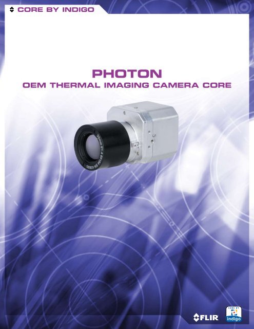
CORE BY INDIGO<strong>Photon</strong>OEM Thermal Imaging Camera Core
PHOTON2.1 inch51.4mmThe Industry Standard Thermal Imaging Camera Core:For Applications Where Reliability and Performance Are PrioritiesThe <strong>Photon</strong> OEM Camera Core is a compact, all-in-one thermal imager with outstandingsensitivity and image quality. The on-focal-plane circuitry, combined with FLIR’s advancedsignal processing electronics, enables the camera to maintain excellent dynamic rangeand image uniformity over a wide temperature range.2.0 inch49.8mmIntegrators have embedded tens of thousands of <strong>Photon</strong> cores in a myriad ofapplications including automotive night vision systems, firefighting equipment, unmannedvehicle payloads, weapon sights, low-power security & surveillance products, and more.1.8 inch45.0mmThe <strong>Photon</strong> OEM Camera Core is designed to be a high-volume thermal imagingcomponent that customers can integrate into products or systems of their owndesign. Most OEM customers connect directly to the <strong>Photon</strong>’s 30-pin connectorfor power (in), video (out), and other functions.The <strong>Photon</strong>’s 30-pin connector also facilitates the interface to camera controldevices, and provides access to the digital data output. OEM customers typicallyorder the <strong>Photon</strong> core in this configuration.<strong>Photon</strong> rear view of 30-pin connector.While FLIR normally sells its factory-calibrated and tested <strong>Photon</strong> cameras with anassociated lens, a lens-less camera core configuration is also available. An optionalsoftware program called Alternate Lens Cal is available to enable customers toperform a supplementary gain calibration.<strong>Photon</strong> Lens-Less Camera Core ConfigurationShown with Optional Aperture Plate InstalledPart Number No Lens 14.25mm 19mm 35mm 50mmNTSC 30Hz 500-0305-01-00 412-0035-14-07 412-0035-09-07 412-0035-17-07 412-0035-18-07NTSC 8Hz 500-0305-01-00S 412-0035-14-07S 412-0035-09-07S 412-0035-17-07S 412-0035-18-07SPAL 25Hz 500-0305-02-00 412-0035-56-07 412-0035-52-07 412-0035-57-07 412-0035-58-07PAL 9Hz 500-0305-02-00S 412-0035-56-07S 412-0035-52-07S 412-0035-57-07S 412-0035-58-07S
<strong>Photon</strong> Benefits• Widest Operating Temperature and Highest Shock Rating of Any Thermal Camera• 2X Digital Zoom Enables Close-Up Imaging and Electronic Pan/Tilt in Zoom Mode• 2-second Turn-On Time for “On-Demand” Applications• Fully Integrated Design Supports OEM and Commercial Customers & Applications• Digital Detail Enhancement (DDE) Sharpening Filter Brings Out Detail in Image DataImages from <strong>Photon</strong>smounted in Ground VehiclesImages from <strong>Photon</strong>s inUnmanned Aerial Vehicles (UAVs)Suspected ImprovisedExplosive Device (IED) islocated under a tankertruck.Vehicles and peopledetected in the vicinity ofwarehouses from 500’altitude.<strong>Photon</strong>’s E-Zoom featuregets a closer look atsuspected IED while stayingat a safe distance.A small vehicle trackedfrom 750’.<strong>Photon</strong>-equipped UGVtracks intruder while onnight perimeter patrol.Surveillance of a tree-linefrom 1,000’.Specifications subject to change without notice.
PHOTON<strong>Photon</strong> OEM ACCESSORY KitFor evaluation purposes, FLIR offers an optional OEMAccessory Kit that enables customers to operate a <strong>Photon</strong>until they develop their own interface. The Kit containsa power supply, breakout box (called an I/O Module),an interface cable, and a small adapter circuit (called aWearsaver) that attaches between the camera connectorand interface cable.The Accessory Kit also includes a rear cover thatencloses the Wearsaver adapter and provides for secureconnection to the interface cable. The end-user only needsto provide a video cable and monitor, and an RS-232 cableif remote control of the <strong>Photon</strong> is desired.<strong>Photon</strong> OEM Accessory KitA camera control software program (GUI) is available fordownload at:www.corebyindigo.com/service/softwareupdates/<strong>Photon</strong> rear view showing15-pin connector<strong>Photon</strong> OEM ACCESSORy Kit ContentsThe <strong>Photon</strong> OEM Accessory Kit part number is 421-0021-00. These items may also be ordered individually.Part accessory Item Functional Description250-0194-00 Wearsaver An adapter that converts the 30-pin SAMTEC connector on the<strong>Photon</strong> power board to a 15-pin D-Sub connector.261-1273-00 Wearsaver Cover Rear cover encloses the wearsaver adapter and provides jack postsfor secure interface cable connection.308-0076-00-02 6’ Interface Cable, Provides electrical interface by means of a 15-pin mating connector<strong>Photon</strong> to I/O Moduleat the camera end, and 18-pin connector at the I/O module end.Optional accessories include 3’ and 10’ interface cable lengths.333-0005-00 I/O Module A molded “break-out-box” providing electrical interface to thecamera, connectors for power-in (Switchcraft), video-out (BNC),com port (RS-232, 9-pin D-Sub), and a 15-pin connector forserial LVDS digital data. The I/O Module is designed to mate with theSIPO for conversion of serial LVDS to a parallel digital data signal.206-0001-20 & AC/DC Power Supply Provides nominal power (9 VDC) to operate the <strong>Photon</strong>.208-0004-02 & Line Cord
OPTIONAL ACCESSORIESPartAccessory ItemFunctional Description110-0102-46SDK for Windows & EmbeddedThe <strong>Photon</strong> SDK enables camera control using one of severalprogramming languages including VB6, VB.net, C#, and C++ (MFC).Code examples are included to help illustrate how some of thecamera control functions can be used.110-0102-63Alternate Lens Cal SoftwareAllows OEM customers that purchase lens-less camera cores toperform a supplementary gain calibration using their own optics,while retaining the original factory calibration data should it beneeded again.261-1357-00Tripod AdapterAdapter furnishes a ¼” x 20 helicoil insert.308-0013-00308-0016-00-03Interface Cable, SIPO to NI PCI-1422Interface Cable, SIPO to Bit FlowRoad RunnerEither of these cables can be used with a SIPO (333-0008-00) totransfer digital data to the selected frame grabber. Contact FLIR’sClient Services for camera files.308-0076-00-01308-0076-00-033’ Interface Cable to I/O Module10’ Interface Cable to I/O ModuleThe standard interface cable provided with the Accessory Kit is 6’.Two other interface cable lengths are available: 3’ and 10’.308-0126-00-01308-0126-00-02308-0126-00-033’ Power/Video Cable6’ Power/Video Cable10’ Power/Video CableInterface cable from <strong>Photon</strong> camera providing connectors forpower in and output video (only) available in 3’, 6’, and 10’ lengths.This cable replaces the standard interface cable and I/O modulewhen serial control and digital video are not required.333-0008-00Serial-In, Parallel-Out Module (SIPO)The SIPO converts serial digital data output into a parallel dataformat for use with a frame grabber. The SIPO mates directlyto the I/O module’s digital data port, and furnishes a 68-pinconnector that can be interfaced to a compatible frame grabbervia a 308-0013 or -0016 digital cable.421-0008-00Rechargeable Battery & CableKit consisting of: - 206-0002-10Battery Pack 7.2V, Li-Ion; Charger- 260-0007-10 Battery CableRechargeable Lithium-Ion battery will power a <strong>Photon</strong> camera for6+ hours on a full charge. The battery is furnished with charger(not shown) and an 8” cable that interfaces to the I/O module. Thenominal voltage output of the battery is 7.2 VDC.421-0025-00Ethernet ModuleThis 100/1000 baseT Ethernet Interface module allows for cameracontrol along with real-time streaming uncompressed video datafrom the <strong>Photon</strong> via standard ethernet hardware. The adapterauto senses network capability and runs at standard 100-megabitor full gigabit ethernet speed. The module includes the ethernetinterface adapter and camera cabling. The module allows captureof both 8-bit data and the full 14-bit bandwidth digital video. Analogvideo is also output via a BNC connector.500-0312-00EMI Rear Enclosure AssemblyWith appropriate grounding, cable shielding, and power, thisenclosure mitigates radiated EMI emissions to near CE class Aperformance levels (~0dB margin).Specifications subject to change without notice.
PHOTONCamera ConfigurationsStand Alone Operation with Accessory KitInterface Cable<strong>Photon</strong> I/O Module Power Supply MonitorAccessory Kit and Customer-Furnished PC: Remote OperationDB-9 SerialCamera Control via RS-232Interface CableI/O Module<strong>Photon</strong> Power Supply MonitorPCAccessory Kit, SIPO and Customer-Furnished Desktop PC: Digital Data CollectionDB-9 SerialI/O ModuleCamera Control via RS-232Interface CableSIPO<strong>Photon</strong> Power Supply MonitorPCCustom Digital Data CableNOTE: An appropriate frame grabber, as well as image acquisition & processing software, must be supplied and supported by the customer.The frame grabber may be either a Bit Flow Road Runner Model 14 or National Instruments PCI-1422 IMAQ, depending on the digital cable and type of software planned for use by the customer.Ethernet Module and Customer-Furnished PC: Digital Data CollectionRJ-45 CAT-5Camera Control & Digital DataInterface Cable<strong>Photon</strong> Ethernet Module MonitorPower SupplyPCThe Ethernet Module enables <strong>Photon</strong> control and video display/capture on a PC. Due to variability in user platforms and networks, FLIR does not guarantee the accuracy of captured video.OVERVIEW OF THE PHOTON ELECTRICAL INTERFACE<strong>Photon</strong> 15-pin D-Sub Connector Pin DefinitionsPin # Signal Name Signal Definition1 VIDEO_HI Analog Video, positive output2 SD_FSYNC+ Digital Port 1 Sync, positive output3 GND Ground4 GND Ground5 GND Ground6 VIDEO_LO Analog Video, negative output7 SD_CLK+ Digital Port 1 Clock, positive output8 SD_DATA+ Digital Port 1 Output Data, positive output9 TX Primary Serial Communication transmit10 PWR_IN Input Voltage11 SD_CLK- Digital Port 1 Clock, negative output12 SD_FSYNC- Digital Port 1 Sync, negative output13 SD_DATA- Digital Port 1 Output Data, negative output14 RX Primary Serial Communication receive15 PWR IN Input Voltage61 511151015-pin HD D-Sub (M)connector on cameraThe 15-pin high density D-Sub connector pin definitions are providedin the case that the wearsaver adapter is used. The signals onthis connector include input power, analog video output, serialcommunication for camera control, and the digital data output.
LENS DATAFocal Length 14.25mm Lens 19mm Lens 35mm Lens 50mm Lensf/ number 1.3 1.4 1.4 1.7Field of View 50° x 38° 36° x 27° 20° x 15° 14° x 11°IFoV (milliradians) 2.667 2.000 1.086 0.760Minimum Focus Distance 0.13 meters 0.3 meters 0.7 meters 1.8 metersHyperfocal Distance 5 meters 7.5 meters 26 meters 35 metersHyperfocal Depth of Field 2.5 meters 3.8 meters 13 meters 18 metersWeight (as pictured) 179 g 155 g 209 g 251 gLength (Lens only) 30.7mm 19.5mm 43.4mm 66.9mmDiameter (maximum) 42.0mm 26.0mm 42.0mm 45.0 mmAthermal DesignYes – All LensesNominal Wavelength8.0 to 14.0 microns* Note: <strong>Photon</strong> lenses are not designed, calibrated, or specified for close focus use. Questions? Email: oem@indigosystems.comDirect Interface to SAMTEC ConnectorPin definitions of the 30-pin board connector forinterface to the SAMTEC TFML-115-02-S-D-Pconnector (J1) are shown below. This is the primaryconnector interface to the <strong>Photon</strong> camera.304 229330-pin SAMTEC (M) connector oncamera1Note that FLIR’spinout differs fromSAMTEC pinoutPower Board to External I/O Connector Pin DefinitionsPin # Signal Name Signal Definition1,2,5,6 GND Ground3 3.15V_OUT 3.15V output4 PWR_IN Input voltage7 1.5V_OUT 1.5V output8 Not connected9 RX2 Spare Serial Communication receive10 RX Primary Serial Communication receive11 TX2 Spare Serial Communication transmit12 TX Primary Serial Communication transmitNote: The mating connector is SAMTEC SFML-115-T1-S-D-KPin # Signal Name Signal Definition13 LVDS_VID2+ Digital Port 2 Output Data, positive output14 SD_DATA- Digital Port 1 Output Data, negative output15 LVDS_VID2- Digital Port 2 Output Data, negative output16 SD_ DATA+ Digital Port 1 Output Data, positive output17 LVDS_VID1+ Digital Port 2 Sync, positive output18 SD_FSYNC- Digital Port 1 Sync, negative output19 LVDS_VID1- Digital Port 2 Sync, negative output20 SD_ FSYNC+ Digital Port 1 Sync, positive output21 LVDS_VID0+ Digital Port 2 Clock, positive outputPin # Signal Name Signal Definition22 SD_CLK- Digital Port 1 Clock, negative output23 LVDS_VID0- Digital Port 2 Clock, negative output24 SD_ CLK+ Digital Port 1 Clock, positive output25 TEMP2 Temp Sensor port 226 DIS0_EXT Frame Sync input27 DIS2_EXT Discrete Input Channel 228 VIDEO_LO Analog Video, negative output29 DIS1_EXT Discrete Input, Channel 130 VIDEO_HI Analog Video, positive outputSpecifications subject to change without notice.
SpecificationsSystem OverviewSystem TypeSensor TypePixel SizeSpectral BandPerformanceUncooled LWIR Thermal Imager324x256 VOx Microbolometer38 μm7.5 – 13.5 μm< 85mK NEdT at f/1.6OutputsAnalog VideoDigital VideoNTSC @ 30 HzPAL @ 25 Hz (optional)9 Hz option for export (factory set)8- or 14-bit serial LVDSOperationImage ControlCamera ControlSignal InterfacePowerInput VoltagePower DissipationTime to ImageInvert, revert, 2x digital zoom, digital detail enhancement (DDE)Autonomous, or manual via GUI or RS-232 serial command30-pin SAMTEC connector for power, video, communication, digitaldata, external sync, direct access to e-zoom & polarityRange 5 – 24 VDC1.6W steady-state~2 secondsSANTA BARBARACVS World HeadquartersFLIR Systems, Inc.70 Castilian Dr.Goleta, CA 93117USAPH: +1 805.964.9797FX: +1 805.685.2711EnvironmentalOperating Temp Range-40 – +80 °C external tempStorage Temp Range-50 – +85 °C external tempScene Temp RangeTo 150 °C standardShock70 g shock pulse, 11ms half-sine profileVibration4.3 g ms random vibration for 8 hours (three axes)Humidity Non-condensing, 5% – 95%Physical AttributesSize51.4 x 49.8 x 34.0 mm (less lens)Weight97g (core only, no lens or cover)Mounting Interface7 heatsink attach points, M3EUROPECVS Eurasian HeadquartersFLIR Systems CVS BVVerlengde Poolseweg 34-464818 CL BredaNetherlandsPH: +31 (0) 76.524.46.86FX: +31 (0) 76.524.46.66PORTLANDCorporate HeadquartersFLIR Systems, Inc.27700A SW Parkway Ave.Wilsonville, OR 97070USAPH: +1 877.773.3547FX: +1 503.498.3904BOSTONFLIR Systems Boston, Inc.25 Esquire RoadNorth Billerica, MA 01862USAPH: +1 877.773.3547PH: +1 800.GO.INFRAFX: +1 978.901.8885www.flir.comwww.corebyindigo.comEquipment described herein may require US Government authorization for export purposes. Diversion contrary to US law is prohibited.Specifications are subject to change without notice. ©2007 FLIR Systems, Inc. All rights reserved. Rev C 3/07