4 CH MPEG-2 Digital Video Recorder
4 CH MPEG-2 Digital Video Recorder
4 CH MPEG-2 Digital Video Recorder
- No tags were found...

Create successful ePaper yourself
Turn your PDF publications into a flip-book with our unique Google optimized e-Paper software.
User’s Manual4 <strong>CH</strong> <strong>MPEG</strong>-2<strong>Digital</strong> <strong>Video</strong> <strong>Recorder</strong>780 V1.1Please read these instructions thoroughly before operation and retain it for future reference.
WARNINGAll the safety and operating instructions should be read before operation.The improper operation may cause permanent damage.• This adaptor is only for this machine.Do not use it for other electronic products or it will damage other products.• Please lift and place this equipment gently.• Do not expose this equipment to direct sunlight.• Do not use this equipment near water or in contact with water.• Do not spill liquid of any kind on the equipment.• Please power down the unit before unplugging.• Do not block the ventilation holes at the top and bottom of theunit.• Do not switch the Power On & Off within short period of time(within 3 seconds).• Installation should be made by qualified service personnel.The lightning flash with arrowhead symbol, within an equilateraltriangle, is intended to alert theuser to the presence of uninsulated"dangerous voltage" within the product's enclosure that may be ofsufficient magnitude to constitute arisk of electric shock to persons.The exclamation point within an equilateral triangle is intended to alert theuser to the presence of important operating and maintenance-(servicing)instructions in the literature accompanying the appliance.
TABLE OF CONTENTS1. What do you get ?FEATURESPACKAGE CONTENT112. Before OperationINSTALLATION GUIDEFRONT PANELREAR PANEL2353. Basic OperationGETTING STARTEDOPERATIONRECORDINGPLAYBACK4. Detailed Menu SetupMAIN MENUMENU OPTIONSRECORDTIMER SETUPCAMERADETECTIONDISPLAYPIP OPTIONDWELL SETUPUSERSYSTEMBUZZER SETUPREMOTE SETUPUPGRADE SETUPEVENT6778101111121314151718192022232425
5. Advanced OperationOPERATION OPTIONS2X ZOOMVIDEO LOSSSEAR<strong>CH</strong>USB BACKUPKEY LOCKRS-232 PROTOCOLTROUBLE SHOOTINGSPECIFICATIONS2626262730313132336. APPENDIXAPPENDIX A – INSTALL THE HDDAPPENDIX B – REPLACE THE HDDAPPENDIX C – PIN CONFIGURATIONSAPPENDIX D – RECORDING SPEEDAPPENDIX E – NETWORK APPLICATION3434353638
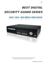
What do you get ?FEATURES• <strong>MPEG</strong>-2 compression format• USB Backup ( backup files by USB Flash Drive and USB HDD devices).• High resolution: 720 X 480 pixels 720 x 576 pixels • Duplex function (record and playback)• Picture-in-Picture (PIP) in live• Motion detection function• Alarm input & output function• <strong>Video</strong> loss detected on each channel• Linear Zoom (2x)• Recording rate:Up to 30 frames/sec (NTSC) ; Up to 25 frames/sec (PAL).• Support 1 HDD, IDE TYPE• Quick multiple search by event / time list• Security password protectionPA PACKAGE CONTENT<strong>Digital</strong> <strong>Video</strong> <strong>Recorder</strong>(with HDD cartridge)User’s ManualPower Adaptor and Cord Accessories pack HDD screwsWarning:1. Please check the package to make sure that you receive the complete accessories shown above.2. The adaptor is DC19V 2A. If it is damaged, users can find replacement adaptor locally with this specification.1
RISK OF ELECTRIC SHOCKDO NOT OPENBefore OperationINSTALLATION GUIDE1. Shown below is an example of connecting the DVR to existing Observation System.2. Install HDD (The compatible HDD models are listed in the following table).Please refer to page.34 Appendix A for installation instructions.Note: 1. The HDD must be installed before turning on the DVR. If HDD is not installed, the DVR wouldfunction as a 4 <strong>CH</strong> multiplexer.2. Users need to set the HDD on the Master mode for system detecting.AlarmSensorPCPTZMain Monitor12MAINUSB USBPORTWARNING : TO REDUCE THE RISK OFDO NOT REMOVE COVER (OR BACK).NO USER-SERVICEABLE PARTS.REFER SERVICING TO QUALIFIEDSERVICE PERSONNEL.34CALLINOUTEXTERNAL I/ODC 19VUSB Flash DriveCamera 1~4Call MonitorPowerCOMPATIBLE HARD DISK MODELSManufacturer Model Capacity RotationHITA<strong>CH</strong>I Deskstar 180 GXP (120 GB) 120GB 7200 rpmHITA<strong>CH</strong>I Deskstar 7K250, HDS722516VLAT20 160GB 7200 rpmHITA<strong>CH</strong>I Deskstar 7K250, HDS722525VLAT80 250GB 7200 rpmIBM Deskstar 120GXP (80GB) 80GB 7200 rpmIBM Deskstar 120GXP (120GB) 120GB 7200 rpmMaxtor DiamondMax 536DX(60GB) 4W060H4 60GB 5400 rpmMaxtor DiamondMax Plus 9 80GB 7200 rpmMaxtor DiamondMax Plus 9, Model#6Y120L 120GB 7200 rpmMaxtor DiamondMax Plus 9, Model#6Y160L0 160GB 7200 rpmMaxtor MaxLine Plus Ⅱ, Model#7Y250P0 250GB 7200 rpmSeagate Barracuda ATA IV, ST380021A 80GB 7200 rpmSeagate Barracuda ATA V, ST3120023A 120GB 7200 rpmSeagate Barracuda 7200.7 Plus, ST3160023A 160GB 7200 rpmWestern <strong>Digital</strong> Caviar WD1200BB-00CAA1 120GB 7200 rpmWestern <strong>Digital</strong> Caviar WD2000BB-00DWA0 200GB 7200 rpmWestern <strong>Digital</strong> CaviarSE WD2500JB 250GB 7200 rpmNOTE: For non-stop long-time recording, we suggest to have two HDDs for recording to ensuregood reliability of HDD.2
FRONT PANEL1. LED LIGHTThe LED Light is ON under following conditions.•HDD : HDD is reading or recording.•HDD Full : HDD is full•ALARM : To turn off the ALARM LED light, please refer to page.15andset the ALARM mode as OFF.•TIMER : When Timer is Enabled•PLAY : Playing mode•REC : Recording mode2. MENUPress MENU to enter main menu.3. ENTERPress ENTER for confirmation4. SEAR<strong>CH</strong>Press SEAR<strong>CH</strong> for searching recorded video.5. ZOOMPress the ZOOM button Enlarge the picture (2X).6. /+ Picture in PicturePIP: Press “PIP” button for Picture in Picture screen.+ : Press “+ ” button can change the setting in the menu.7. /- 4-channel display mode: Press “ ” button for 4 <strong>CH</strong> display modes- : Press “ - ” button can change the setting in the menu.3
8. SLOWTo slow down the speed of playing mode.9. FF / ►•FF:Play video fast forward. (Press FF button again to adjust speedas 3, 45, 600 times)• ► : Under setup mode, it works as Rightbutton.10. REW / ◄•REW:Play video fast backward. (Press REW button again to adjust speed as 15, 90, 600 times)• ◄ : Under setup mode, it works as Leftbutton.11. STOP / ▼•STOP : Under DVR Play mode, it can stop the action.• ▼ : Under setup mode, it works as Down button.12. PAUSE / ▲•Pause : Under DVR play mode, it can pause the action.• ▲ : Under setup mode, it works as Up button.13. PLAYPress PLAY toplayback recorded video.14. RECPress REC to start recording.15. CAMERA SELECT (1-4)Press the Camera Select (1-4) to select the channel.16. ENTER + SEAR<strong>CH</strong>Press both “ENTER” + “SEAR<strong>CH</strong>” buttons to enter the USB Backup menu.17. ENTER + MENUKey Lock (and Key Unlock).18. ENTER + ZOOMPTZ control enable/disable.4
RISK OF ELECTRIC SHOCKDO NOT OPENWARNING: TO REDUCE THE RISK OF ELECTRIC SHOCK,DO NOT REMOVE COVER (OR BACK).NO USER-SERVICEABLE PARTS INSIDE.REFER SERVICING TO QUALIFIEDSERVICE PERSONNEL.REAR PANEL712MAINUSB PORT USB34CALLINOUTEXTERNAL I/ODC 19V1 2 3 4 51. USBConnect to a USB HDD or a USB Flash Drive.2. EXTERNAL I/O•Controlled remotely by an external device or control system such as <strong>Video</strong> Web Server or PC.•Alarm input, external I / O expansion.3. VIDEO INPUT (1-4)Connect to video source, such as camera.4. CALLConnect to CALL monitor. Show the Switch Display.When alarm trigger happens, it will change to dwell modes of alarm(refer to p.18)5. FANFor ventilation, do not block the opening.6. POWERPlease use the provided power cord.7. MAINConnect to the main monitor.Warning:1. The adaptor is only for this machine. Do not use it for other electronic product or it might damage other products.2. The adaptor is DC19V 2A. If it is damaged, users can find replacement adaptor locally with this specification.5
Basic OperationGETTING STARTEDBefore using the DVR, please have a HDD installed ready; otherwise, it will function as a 4 <strong>CH</strong> multiplexer(refer to Appendix A and Appendix B for installation or removal of a HDD).1. Connect the AC power cord and plug into an electrical outlet. The power LED indicator light will be on.2. It takes approximately 5 to 15seconds to boot the system with the message:”Booting”. The Power LED will turn fromorange to green and Alarm LED will be on.3. Before operating the DVR, set the system time first. (refer to page 20).NOTE : 1. If the HDD is not installed correctly or not installed, “NO HDD!”, “HDD KEY UNLOCK!”, “UNKNOWNFILE SYSTEM! PLEASE FORMAT IT!” messages will appear for 3 seconds, and then return to 4 <strong>CH</strong>Multiplexerdisplay mode.*** “UNKNOWN FILE SYSTEM!”: The format of HDD is not accepted by the DVR system. The system onlyaccepts EXT3 format. Users can format HDD by selecting “HDD FORMAT” on SYSTEM menu.2. To switch the system, you need to unplug the ACpower, then press “FF” button or “REW” button and connectthe AC power cord, it will switch to NTSC system or PAL system. And the DVR will be auto-detecting.6
OPERATIONRECORDINGThe DVR offers 2 recording modes(Timer, Manual). Under the recording status, if power is off accidentally, therecorded video will still be stored in the HDD. DVR will return to previous recording setting after power restores.The first character: ( Frame/Sec)A : 30 25 B : 15 12 C : 5 4 The second character: (Record Quality)a : Best b : High c :Normal d : Basic007.2 GB: the available space of HDD isO/W: HDD is overwrittenNOTE : Under O/W Recording mode, previously recorded files will be automatically overwritten.There are two recording modes: Timer and Manual Recording.1. TIMER RECORDINGRecording is scheduled by a Timer. It will be indicated by the symbol .2. MANUAL RECORDINGRecording is initiated manually by pressing the REC button. SymbolIf the system is shut down, the system will resume recording automatically.will be shown.Note: To prolong the life span of HDD, please confirm that the power of the machine is off beforeunplugging the power cord. Moreover, if the power system is unstable, we suggest installingUPS .7
PLAY BACKPress the “PLAY” button to display the last video.The screen will display the last video of a channel which is in display.When all channels are on screen display, and users press the “PLAY” button, the menu (PLAY MODE) willshow up for users to select channels.When changing the channels, users can either press the buttons “1-4”on the front panel or enter the “PLAYMODE”menu for displaying.Press “ENTER” button to enlarge the video to full screen.8
1. FF (FAST FORWARD) & REW (FAST REWIND)Increase the speed of Fast Forward and Rewind on the DVR by pressing the “FF” button.In the Play mode, press “ FF ” once to get 3X speed forward and press twice to get 45X speed, andthe maximum speed can reach 600X.Press “REW ” once to get 15X speed rewind and press twice to get 90X speed, and the maximumspeed can reach 600X.2. SLOW FORWARDSlow down the speed of Forward on the DVR by pressing the “SLOW” button.In the Play mode, press the “SLOW” button to enter the Slow mode.Press ” SLOW ” once to get 1/4X speed forward and press “ SLOW ” to get 1/8 speed,… and theslowest speed can reach 1/16X.3. PAUSEThe still image will be displayed on the screen. (Please refer to page.11 for “STOP RECORD”.)4. STOPPress “STOP” button to stop displaying a video.5. IMAGE JOG DIALIt will allow you to manually view video frame-by-frame, one image at a time.In PLAY mode, press “PAUSE ”, it will let the video pause.Press “ ► ” button advances one image.Press “ ◄ ” button moves back one image.9
▲Detailed Menu SetupMAIN MENUPress “MENU” button to enter the main menu at first time.The default password is 000000.There are 7 options available in the Main Menu.RECORD --------Record SchedulingCAMERA --------Camera SetupDETECTION ----Motion / Alarm SetupDISPLAY -------- Display Mode SetupUSER ------------ User Password SetupSYSTEM -------- System SetupEVENT ---------- Event ListOutlined below are the buttons used for Menu setting :•“▲” “▼”“ ”“ ”: Move the cursor.▲• “ + ” and “ - ” : Select the numbers/ change values.•ENTER : Enter a submenu mode / an option under a submenu for browsing /Confirm the selection.•MENU : Enter the menu mode / Confirm the change/ Exit a menu.10
MAIN OPTIONSRECORDPress the “▲” “▼”“ ”“ ”buttons to move the cursor.▼▼Press the “+”“-”buttons to change the digit.Press the “MENU” button to confirm the changes/ to exit the menu.1. STOP RECORD(MANUAL RECORD)The system will stop manual recording function during the recording period if the setting is “YES”. And then,press the “ENTER” button to save the changed value.Note: 1. The users have to stop recording function on this menu because the users cannot stop it by pressing anyfront-panel buttons during the recording period.2. In the Timer Recording mode, users have to either change the RECORD METHOD setting from TIMER to MANUALor change the timer setting to stop the timer recording function.2. FRAME / SECSelect the recording speed. The options are as following :NTSC-30、15 、 5 PAL-25、12 、43. QUALITYThere are four image qualities : BEST, HIGH, NORMAL, BASIC.4. HDD OVERWRITETo set the HDD OVERWRITE. When the HDD is going to be full underO/W recording mode,previous recorded files will be overwritten without furtherwarning notices if the HDD OVERWRITE is “ON”.5. RECORD METHODThere are two recording methods: MANUAL ( by pressing the “REC” button) and TIMER ( by setting the timerrecording).***On the Timer Recording mode, users have to either change the RECORD METHOD setting from TIMER toMANUAL or change the timer setting to stop the timer recording function.11
TIMER SETUPPress “▲” “▼”“ ”“ ” buttons to move the cursor.▼▼Press “+”“-”buttons to change the digit.Press “MENU” button to confirm the changes/ to exit the menu.1. DAYChoose the day for recording. The options are:MON(Monday) , TUE (Tuesday), WED (Wednesday), THU (Thursday), FRI (Friday), SAT (Saturday),SUN (Sunday), MO-FR (Monday to Friday), SA-SU (Saturday to Sunday), OFF, and DAILY(on each day).* Date could be changed by “+” and “-” buttons.2. STARTThebeginning of recording time.3. ENDThe end of recording time.NOTE: If users want to record a video from 11 p.m. to 2 a.m. , and users need to set two differentperiods for recording. The first period will be 23 to 24, the second period will be 0 to 2.The number of ending time must be greater than the number of beginning time.12
CAMERAPress the “ ”“▼▼”buttons to move the cursor.Press the “+”“-”buttons to change the option/digit.Press the “MENU” button to confirm the changes/ to exit the menu.1. TITLEAssign a title to each channel. The default title is the camera’s number (Up to 8 characters).2. REC (RECORD)Select a channel to record.ON : when the timer input is triggered, DVR will record a video.OFF : DVR will not record.3. BR (BRIGHTNESS)Adjust the brightness of each channel. The level is from 0 to 63.4. CT (CONTRAST)Adjust the contrast of each channel. The level is from 0 to63.5. CL (COLOR)Adjust the color of each channel. The level is from 0 to 63.6. HUE (HUE)Adjust the hue of each channel. The level is from 0 to 63.7. CAMERA DEFAULTThe setting of BR/CT/CL/HUE will go back to the default value, which is 31, when users press”cameradefault”.13
DETECTIONPress the “▲” “▼” buttons to move the cursor.Press the “+”“-”buttons to change the option.Press the “MENU” button to confirm the changes/ toexit the menu.1. DET (DETECTION)The motion detection on each channel can be turnedON or OFF individually.2. AREAPress the “ENTER” button to set target-area.In this function,it is defaulted to detect the whole area.After entering the setting, users will see the pink area, which means the undetected area,and users can set the area to be detected, and which will turn from pink to transparent.The Pink target represents the undetected area.The Transparent target represents the Motion Detection Area.The beginning of Motion Detection Setting-Detect all targetsMotion Detection Setting-One Target undetectedMotion Detection Setting –A row-target detectedMotion Detection Setting –A detected target14
▲▼▼▼: navigates between targets.- :turns all targets on the screen ON/ OFF.+ : press once to set a motion target, press twice to set a row of motion target.3. LS (Level Sensitivity)Comparing the difference between two images to allow the system to start motion detection function.Lower number = higher sensitivity for motion detection. The highest sensitivity setting is 0,the lowest sensitivity setting is 15. The default value is 06.4. SS (Spatial Sensitivity)Set the number of motion detection targets (from 1-99 target areas). The highest sensitivity setting is 0, thelowest sensitivity setting is 15. The default setting is 01.Note:The setting of Spatial Sensitivity cannot be more than the number of targets set in the AREA.5. TS (Temporal Sensitivity)The system will start the motion detection function if the continuous fields are all different.The highest sensitivity setting is 0, the lowest sensitivity setting is 15. The default setting is 01.6. RE (Reference)Set the Reference image to which the current screen is compared (from 0-63).For example, the value 8 would compare the current image tothe 8 th previous image. The highervalue will increase the sensitivity. The default value is 10.7. ALARMSelect LOW / OFF / HIGH for alarm polarity. The default alarm value is OFF.8. EVENT DURATIONSet the event duration time.9.DAY. START. END of DetectionChoose the day for recording, the beginning of recording time and the end of recording time.Note: When the motion detection function is triggered during the recording period. The symbol will be shown .When the alarm function is triggered during the recording period. The symbol will be shown .15
DISPLAYPress the “▲” “▼”“ ”“ ”buttons to move the cursor.▼▼Press the “+”“-”buttons to change the option/digit.Press the “MENU” button to confirm the changes/ to exit the menu.1. TITLE DISPLAYSet the title shown on monitor.12. OSD COLORSelect the OSD (On Screen Display) color. The options are WHITE,RED, YELLOW, CYAN, BLUE,PINK, GRAY, ORANGE.3. CURSOR COLORSelect the cursor color. The options are RED, YELLOW, GREEN, CYAN, BLUE, PINK,GRAY, ORANGE .NOTE: The setting of OSD COLOR and CURSOR COLOR cannot be the same.4. LOSS SCREENSelect a way to display the screen when the video input is out of order. The options are BLACK, BLUEand RETAIN (retain the last picture).5. OSD POSITIONSelect the OSD POSITION. The options are NORMAL (in upper right corner) or CENTER.6.PLAYBACK METHODSelect a video type to playback. The options are frame and field. 1 frame equals two fields.7. PIP OPTION / DWELL OPTION(see p.17,18)To enter the PIP setting menu/DWELL setting menu.16
PIP OPTIONPress the “▲” “▼” buttons to move the cursor.Press the “+”“-”buttons to change the option.Press the “MENU” button to confirm the changes/ to exit the menu.1. FULL SCREENThe full screen background picture display.2. PIP SCREENThe picture with a 1/9 size screen “insert”.3. POSITIONThere are six position settings : D/L (Down/Left), D/M (Down/Middle), D/R (Down/Right),U/L (Up/Left), U/M (Up/Middle), U/R (Up/Right).17
DWELL OPTIONPress the “▲” “▼”“ ”“ ”buttons to move the cursor.▼▼Press the “+”“-”buttons to change the option.Press the “MENU” button to confirm the changes/ to exit the menu.1. NORMTo set up the DWELL time period that each channel auto sequentially shows on callmonitor. The level is from 01 to 24 Sec or OFF.2. ALARMTo set up the DWELL time period when alarm input is triggered.The level is from 01 to 24 Sec or OFF.18
USERPress the “▲” “▼”“ ”“ ”buttons to move the cursor.▼▼Press the “+”“-”buttons to change the option/digit.Press the “MENU” button to confirm the changes/ to exit the menu.1. USERTo set up the user’s account for controlling. It allows 7 users setting.Supervisor – Control all the functions.Other Users – View all functions except themenu setting and event listcleaning.2. PASSWORDTo set the security password for each account.The maximum length of user’s password is 6 digits.19
SYSTEMPress the “▲” “▼”“ ”“ ”buttons to move the cursor.▼▼Press the “+”“-”buttons to change the settingPress the “MENU” button to confirm the changes/ to exit the menu1. KEY MUTETo set the KEY MUTE. When the setting is “ON”, there will be no sound when you press any key.2. BUZZER (see p.22)To enter the buzzer setup menu.3. MESSAGE LAT<strong>CH</strong>The default setting of messages displaying is 10 seconds when the setting is “ON”.4. DATE DISPLAYSet the date display. The options are Y/M/D, D/M/Y, M/D/Y and OFF.5. DATESet the date.6. TIMESet time.7. HDD FORMATFormat HDD by selecting “FORMATE” option. After formatingthe HDD, the system will restart.Note:1.The system will take about 12minutes to format 80GB HDD.If the HDD have been formatted before, it takes about 4 minutes to format it.2.After formatting the HDD, you would find that the space about 12% is occupied.20
8. SYSTEM RESETReset all system settings back to factory default setting.9. LANGUAGESelect one language for menu displaying. The options are ENGLISH and <strong>CH</strong>INESE. The system willautomatically save the setting.10. UPGRADE(see p.24)To enter the upgrade setup menu.11. REMOTE(see p.23)To enter the remote setup menu.21
BUZZER SETUP1. BUZZERSet the BUZZER “ON”, it will buzz when event occurs.2. EXT ALARMTo set the EXT ALARM. It will be trigged by event occurrence when the setting is “ON”.3. VLOSS ALARMTo set the VLOSS ALARM. When the setting is “ON”, the alarm will start after settingBuzzer, EXT Alarm or Alarm Duration.4. MOTION ALARMTo set the MOTION ALARM. When the setting is “ON”, the alarm will start after settingBuzzer and EXT Alarm.22
REMOTE SETUPPress the “▲” “▼” buttons to move the cursor.Press the “+”“-”buttons to change the option.Press the “MENU” button to confirm the changes/ to exit the menu.1. REMOTE MODESet the remote mode for connection with computer via RS-232 or RS-485.(refer to page. 30 for RS-232 & RS-485 Remote Control).2. BAUD RATESet the remote protocol transmitting baud rate. Available options are115200, 57600, 19200, 9600, 4800, 2400, 1200.3. IDTo control different DVR by setting remote protocol. ID number can be set from 000 to 254.23
UPGRADE SETUPUser can upgrade the DVR software by USB storage device.YES: UpgradeNo : CancelIt will take few minutes to upgrade the whole system. Users cannot unplug the power cord, or turn off thepower during the period of upgrading.It will reset the system setting will be disable when the system is upgraded.Therefore, the users have to reset all settings after upgrading.<strong>CH</strong>ECK CRC: The system will check the firmware status to ensure the quality of system.24
EVENTPress the “▲” “▼” buttons to move the cursor.Press the “ENTER” button to get into the submenuThe EVENT shows the recording list of different types.The VLOSS section lists the record of video loss.The ALARM LOG section lists the record of triggering by externalI/O alarm.The MOTION LOG section lists the record of triggering by motion detection.The ALL LOG section lists all types of records.The DELETE ALL option will delete all records.A single page can display 12 recorded events.Press “ ” or “ ” button to change the pages(Up to 256 records).▼▼PWR RESET: The system will automatically record when the system has been reset.25
Advanced OperationOPERATION OPTIONS2X ZOOMPressthe “ZOOM” button, it displays zoomed picture on main picture and a small inserted window.The inserted window contains a movable 1/4 view size of the appointed camera. The range is 2X.2004 MAY-27 [THU] PM 01:45:37CAMERA01• Press the “ZOOM” button again to exit the zoom pointer.• Press Camera 1-4 button to select a channel.• Press ▲▼ buttons to move the zoom position.▼▼VLOSS (VIDEO LOSS)The screen will display “ VLOSS” in the center of display picture, if the video input is not connected properly.26
SEAR<strong>CH</strong>Press “SEAR<strong>CH</strong>” button to play the recording.Select a channel for searching a video record.Press “▲”“▼”buttonsto select camera.Press the “ENTER” button to get into menu/ submenuPress the “MENU” button to confirm the changes/exit the menu[SEAR<strong>CH</strong> MODE]Press the “ENTER” button to get into each submenu.1. EVENT SEAR<strong>CH</strong>Display all the videos, which have been motion triggered on the recording mode.2. TIME SEAR<strong>CH</strong>Enter a time period for searching a video.3. LIST ALLList all video records.27
Press the “▲”“▼”buttonsto select one record.Press the “ENTER” / “PLAY” buttons to display.1. Y/M/DThe Month and the Date display(Year/Month/Date).2. HO:MI:SEThe beginning of recording time(Hour:Minute:Second).3. MI:SEThe duration of playing time(Minute:Second).4. TYPED1: Multiplex mode (input images of a channel at a time).28
USB BACKUPUsers may have to format the USB memory device( USB Sticker and USB HDD devices )by PC before connecting to the DVR.Press both “ENTER”+ “SEAR<strong>CH</strong>” buttons, enter the USB BACKUP mode.Users can save files into the USB storage device, and read filesby personal computer.The system will detect the USB storage device automatically. it will show “DETECTING USB DEVICE”The symbol [ ] shows the available space of the USB storage device.And press “ENTER”, you can see this screen.Press “◄”“►”buttons to select a channel or move to the next digit.Press “+”“-”buttons to change the digit.Step 1: Choose a certain camera by pressing “◄”“►”buttons.Step 2: Enter the beginning and the end of time by pressing “+”“-”buttons.Step 3: Select OK by pressing “ENTER” button (shows the recording space).Step 4: Select OK again to start to backup a file.[ ]/[ ]: [ Recording space ] / [ Total available space of the USB memory device ].NOTE:1. The USB memory device can only be detected by these three file types:FAT32 (WINDOWS), EXT3 (LINUX), EXT2 (LINUX)2. The system will take a few minutes to search if the file is too large.3. The backup files can only be read by WinDVD and PowerDVD software.29
KEY LOCKFor advanced security, users can “Lock” the buttons on your DVR. Key-Lock prevents other people from using the system.Press “ENTER” + “MENU” at the same time to enable Key Lock.Press “ENTER” + “MENU” at the same time and key in password (Default : 000000),and then press “ENTER“ to disable Key Lock.NOTE: To switch to different USER, press “ENTER” + “MENU” buttons to “KEY LOCK” and then enter the different user’spassword to UNLOCK.RS-232 REMOTE PROTOCOLYou can use the PC keyboard to simulate DVR keypad.DATA: REMOTE PROTOCOL using 8 bit data、1 start bit、1stop bitACT CØH ID FUNCTION STOP(FFH)(7FH)FUNCTION CODE ASCII FUNCTION CODE ASCIIKEY_MENU 0x4D M KEY_PLAY 0x50 PKEY_SEAR<strong>CH</strong> 0x73 s KEY_DOWN 0x4E NKEY_ENTER 0x0D ENTER KEY_RIGHT 0x52 RKEY_QUAD 0x51 Q KEY_POWER 0x57 WKEY_ZOOM 0x5A Z KEY_KEY_LOCK 0x4B KKEY_PIP 0x70 p KEY_<strong>CH</strong>1 0x31 1KEY_SLOW 0x53 S KEY_<strong>CH</strong>2 0x32 2KEY_REC 0x72 r KEY_<strong>CH</strong>3 0x33 3KEY_LEFT 0x4C L KEY_<strong>CH</strong>4 0x34 4KEY_UP 0x55 U30
TROUBLE SHOOTINGWhen malfunction occurs, it may not be serious and can be corrected easily. The table below describes some typicalproblems and their solutions. Please check on them before contacting your DVR dealer.PROBLEMNo powerNot working when pressing anybuttonNo recorded videoTimer Record enable does notworkingNo live videoNTSC & PAL System switchUnder overwritting and duplexmodes, the playback motion isinterruptedSOLUTION• Check power cord connections.• Confirm that there is power at the outlet.• Check if it is under Key Lock mode.• Press "MENU" & "ENTER" to exit Key Lock mode.• Check if the HDD is installed properly.• Check if the Record Enable is set to YES• Check camera video cable and connections.• Check monitor video cable and connections.• Confirm that the camera has power.• Check the setting of camera lens.To switch the system, you need to unplug the AC power, thenpress “FF” or “REW”and plug inthe AC power cordagain.(Please refer to page.6)please press “STOP” button and then the “PLAY” button to playagain31
SPECIFICATIONS<strong>Video</strong> FormatHard Disk StorageResolutionRecording ModeCamera Input SignalMain Monitor OutputCall Monitor OutputUSB InterfaceMotion Detection Sensitivity<strong>Video</strong> Loss DetectionRefresh RateRecording RateDwell TimePicture in PictureKey LockPicture ZoomCamera Title<strong>Video</strong> AdjustableAlarm InputNTSC/EIA or PAL/CCIRIDE type, UDMA 66, supported a over 250 GB HDD720 x 480 pixels , 720x576 pixels Manual / TimerComposite video signal 1 Vp-p 75Ω BNC, 4 channelsComposite video signal 1 Vp-p 75Ω BNCComposite video signal 1 Vp-p 75Ω BNC1 port. Support USB 1.1 Device16 LevelsYes120 frames/sec. for NTSC / 100 frames/sec. for PAL*Up to 30 frames/sec. for NTSC / 25 frames/sec. for PALProgrammable (1~24 Sec)Yes (Movable)Yes2X (Movable)8 lettersHue/ Color/ Contrast/ Brightness AdjustableTTL input, High (5V), Low (GND)COM./N.O/N.CRS-232 or RS-485YY/MM/DD, DD/MM/YY, MM/DD/YY, OFFAlarm OutputRemote ControlTime Display FormatPower SourceDC 19VPower Consumption
APPENDIX A– INSTALL THE HDDFollow these steps carefully in order to ensure correct installation.Fig. 1 Fig. 2 Fig. 3 Fig. 4 Fig. 5Step 1 Remove the lid and unscrew the screws from HDD bracket module .Step 2 Insert the HDD into the HDD bracket and screw the four screws. (refer to the Fig. 1, Fig. 2).Step 3 Connect the HDD power cable to the HDD (refer to the Fig. 3).Step 4 Attach the HDD connector to the 40-pin cable, and screw the HDD andthe DVR machine together (refer to the Fig. 3).Step 5 Pull the sides of the lid apart slightly and push the lid down (refer to the Fig. 4).Note: Do not try to retrieve the HDD data by PC. The video file cannot be read by PC,operation on PC would damage the FAT table of the harddisk.APPENDIX B– REPLACE THE HDDFollow these steps carefully in order to ensure correct installation.Fig. 1 Fig. 2 Fig. 3 Fig. 4 Fig. 5Step 1 Remove the lid (refer to the Fig 1).Step 2 Remove the HDD power cable from the HDD (refer to the Fig. 3).Step 3 Take out the HDD from DVR machine carefully.Step 4 Unscrew the four screws connected the hard drive to the bracket and remove theHDD bracket module. Repeat those steps according to the “Install the HDD” section forresetting another HDD (refer to the Fig 4).Step 5 Pull the sides of the lid apart slightly and push the lid down.Note: When HDD works for a period of time, the surface temperature will be high, please notice it.33
APPENDIX C– RECORDING SPEEDThe Recording Time is different based on Recording Speed, Recording Quality and Recording Mode.Please refer to the following table. HDD capability is 250GB.NTSC SYSTEMIPS30155Best106hr212hr636hrMultiplexModeHighNormal132hr213hr264hr426hr792hr1278hrBasic326hr652hr1956hrHDD Type250 GBPAL SYSTEMIPS25124Best106hr212hr636hrMultiplexModeHighNormal132hr213hr264hr426hr792hr1278hrBasic326hr652hr1956hrHDD Type250 GB34
APPENDIX D– PIN CONFIGURATIONS15 pin com port••DVR••9 pin com port••DVRDQR••35
PIN 1. RS232-TX : RS-232DVR can be controlled remotely by an external device or control system, such as a control keyboard, using RS-232 serial communications signals.PIN 2. RS232-RX : RS-232DVR can be controlled remotely by an external device or control system, such as a control keyboard, using RS-232 serial communications signals.PIN 3, 4, 5, 6 ALARM INPUTTo connect wire from ALARM INPUT (PIN 3, 4, 5, 6) to GND ( PIN 9 ) connector.When alarm has been triggered,signal becomes “Low”, and it will stop all alarm activities. Under normal operation, signal remains “High”.PIN 7. EXTERNAL ALARM NCUnder normal operation COM connect with NC and disconnect from NO. But when alarm is triggered, COMdisconnect with NC, and connect with NO.PIN 8. EXTERNAL ALARM NOUnder normal operation, COM will disconnect from NO. But when Alarm is triggered, COM will connect with NO.PIN 9. GNDGROUNDPIN 10. RS485-BDVR can be controlled remotely by an external device or control system, such as a control keyboard, using RS-485 serial communications signals.PIN 11. RS485-ADVR can be controlled remotely by an external device or control system, such as a control keyboard, using RS-485 serial communications signals.PIN 14. ALARM RESET (INPUT)To connect wire from ALARM RESET ( PIN 14 ) to GND ( PIN 9 ) connector, it can disable ALARM. An externalsignal to ALARM RESET ( PIN 14 ) can be used to reset both ALARM OUTPUT signal and DVR’s internal buzzer.When alarm has been triggered, signal becomes “Low”, and it will stop all alarm activities. Under normal operation,signal remains “High”.PIN 15. EXTERNAL ALARM COMUnder normal operation COM connect with NC and disconnect from NO. But when alarm is triggered, COMdisconnect from NC, and connect with NO.36
APPENDIX E– NETWORK APPLICATION<strong>Video</strong> Web Server Features• Compatible with most of CCTV Products; empower any video output device watching andcontrolling on the Internet or LAN• Auto Network Reconnection (ANR)• Upgrade firmware & AP from FTP site via <strong>Video</strong> Web Server• Support Watch dog function• Support Dynamic IP address via a router.• Support 4 alarm inputs• Duplex function, record and playback simultaneously at client site• Auto e-mail warning system which will remind you if external alarmhappens• Intelligent non-stoppable recording function after ANR• Support Multi AP screens Unique video player• Alarm trigger recording function.<strong>Video</strong> Web ServerDVR Control1 ) Connect the Sub-D plug of <strong>Video</strong> WebServer with our own brand DVR products.GNDALARMINPUT2<strong>Video</strong> Web ServerALARMINPUT1NORMALLOWALARMINPUT3NORMALHIGHALARMINPUT4RS485-BRS485-A4<strong>CH</strong> DVRRS232-TXGNDRS232-RXRS485-BALARM INPUT1RS485-AALARM INPUT2DISK FULLALARM INPUT3REC STARTALARM INPUT4ALARM RESETEXTERMAL ALARM NCEXTERNAL ALARM COMEXTERNAL ALARM NO2 ) Set the “Remote” function in the DVRproducts.NOTE : Remote mode : RS-485,Baud rate : 2400, ID : sameas “I/O port setting” in the <strong>Video</strong>Web Server.3 ) Set the “I/O Port Setting” in the systemconfigof <strong>Video</strong> Web Server.Port1 : 4<strong>CH</strong> DVR, Device ID : 001.37