Product catalog in pdf - Pantron Automation, Inc.
Product catalog in pdf - Pantron Automation, Inc.
Product catalog in pdf - Pantron Automation, Inc.
- No tags were found...

Create successful ePaper yourself
Turn your PDF publications into a flip-book with our unique Google optimized e-Paper software.
<strong>Pantron</strong> <strong>Automation</strong>, <strong>Inc</strong>.<br />
109 Hubbard Street<br />
Belmont, NC 28012<br />
1-800-211-9468<br />
www.pantron.com/us<br />
sales@pantron.com<br />
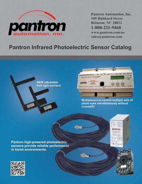
<strong>Pantron</strong> Infrared Photoelectric Sensor Catalog<br />
NEW adjustable<br />
fork light barriers!<br />
Multiplexers to control multiple sets of<br />
photo eyes simultaneously without<br />
crosstalk!<br />
<strong>Pantron</strong> high-powered photoelectric<br />
sensors provide reliable performance<br />
<strong>in</strong> harsh environments.
<strong>Product</strong> Overview<br />
<strong>Pantron</strong> photoelectric systems are designed specifically for harsh environment applications to provide maximum penetration <strong>in</strong><br />
areas where steam, oil, grease, dust, dirt, soap, fog, and other contam<strong>in</strong>ants cause significant problems for ord<strong>in</strong>ary photoelectric<br />
sensors.<br />
A wide variety of amplifiers and multiplexers (multi-channel amplifiers) are available with features <strong>in</strong>clud<strong>in</strong>g manual or automatic<br />
ga<strong>in</strong> adjustment, relay or transistor outputs, time delay, and self-diagnostic features. Multiplexers are designed to control<br />
2, 4, or 8 sets of photo eyes at one time with no cross-talk. The 4 and 8 channel multiplexers offer an <strong>in</strong>terface to connect<br />
additional <strong>Pantron</strong> multiplexers for the synchronization of even more sets of photo eyes.<br />
New adjustable fork light barriers from <strong>Pantron</strong> provide a comb<strong>in</strong>ation of features <strong>in</strong>clud<strong>in</strong>g an adjustable fork width, a programmable<br />
teach mode, and a new PC <strong>in</strong>terface! Setup, monitor, and change the sett<strong>in</strong>gs of the fork light barrier <strong>in</strong> real time from a<br />
computer us<strong>in</strong>g free W<strong>in</strong>Connect software from <strong>Pantron</strong>.<br />
Information About <strong>Pantron</strong> <strong>Automation</strong>, <strong>Inc</strong>.<br />
<strong>Pantron</strong> <strong>Automation</strong>, <strong>Inc</strong>. is the North American distributor for <strong>Pantron</strong> Instruments, GmbH and is located <strong>in</strong> Belmont, NC, just<br />
several miles from the Charlotte Douglas Airport. Office hours are Monday through Friday, 8:00 am until 5:00 PM EST. Call<br />
or visit <strong>Pantron</strong> <strong>Automation</strong>’s website for sales, technical support, and application assistance.<br />
Safety Instructions:<br />
The devices manufactured by <strong>Pantron</strong> Instruments,<br />
GmbH are not to be used for applications where personal<br />
safety is dependent on their function.<br />
Approvals:<br />
All technical specifications <strong>in</strong>cluded here<strong>in</strong> refer to the state<br />
of the art 1/2012. They are subject to modifications.<br />
Applications for <strong>Pantron</strong> Sensors<br />
Two sets of <strong>Pantron</strong> photo eyes configured<br />
<strong>in</strong> through-beam mode and connected to a<br />
2-channel IMX-N24 multiplexer set for<br />
automatic ga<strong>in</strong> control. Used <strong>in</strong> a vehicle<br />
wash to detect cars, trucks, tra<strong>in</strong>s, or buses.<br />
One set of <strong>Pantron</strong> photo eyes configured<br />
<strong>in</strong> through-beam mode and connected to<br />
a s<strong>in</strong>gle-channel manual ISG-N34 amplifier.<br />
Used for operat<strong>in</strong>g automatic overhead<br />
doors for vehicles.<br />
One set of <strong>Pantron</strong> photo eyes configured<br />
<strong>in</strong> diffuse proximity mode and connected<br />
to a s<strong>in</strong>gle-channel automatic ISG-A124<br />
amplifier. Used when wir<strong>in</strong>g to both sides<br />
is not possible.<br />
One set of <strong>Pantron</strong> photo eyes configured<br />
<strong>in</strong> retro-reflective mode us<strong>in</strong>g an external<br />
reflector and connected to a s<strong>in</strong>gle-channel<br />
manual ISM-1000 amplifier. Used for<br />
detect<strong>in</strong>g packages and parts on a conveyor<br />
<strong>in</strong> a clean environment.<br />
Four sets of <strong>Pantron</strong> photo eyes configured<br />
<strong>in</strong> through-beam mode and connected to an<br />
ISM-4000 multiplexer. The ISM-4000<br />
may be programmed to simulate a light<br />
curta<strong>in</strong>. Used to detect logs, no matter the<br />
size <strong>in</strong> a harsh environment.<br />
One set of <strong>Pantron</strong> photo eyes configured<br />
<strong>in</strong> through-beam mode and connected to<br />
a s<strong>in</strong>gle-channel manual ISG-N24 amplifier.<br />
Used for detect<strong>in</strong>g bags of cement<br />
on a conveyor <strong>in</strong> an extremely dusty environment.<br />
One set of <strong>Pantron</strong> photo eyes configured<br />
<strong>in</strong> through-beam mode and connected to<br />
a s<strong>in</strong>gle-channel manual ISG-N34 amplifier.<br />
Used to detect the absolute level of<br />
bulk material <strong>in</strong> a tank.<br />
<strong>Pantron</strong> adjustable fork light barrier used<br />
to detect misaligned caps on bottles.<br />
Fork may be adjusted to various widths<br />
to accommodate different sizes of bottles.<br />
2
Components of a <strong>Pantron</strong> Photoelectric System<br />
S<strong>in</strong>gle set of photo eyes<br />
Example set consists of:<br />
qty 1 - ISG-A124-115VAC Infrared amplifier<br />
qty 1 - IT-M12-15M Infrared transmitter eye<br />
qty 1 - IR-M12-15M Infrared receiver eye<br />
qty 1 - MB11 - 11 p<strong>in</strong> amplifier socket<br />
qty 1 - PanBox 1x1 protective enclosure<br />
Applications:<br />
Detect automobile to engage wash equipment<br />
Level detection of material <strong>in</strong> a b<strong>in</strong><br />
Presence detection on a conveyor<br />
Two sets of photo eyes<br />
Example set consists of:<br />
qty 1 - IMX-N34-24VAC Infrared multiplexer w/ time delay<br />
qty 2 - IT-M12-15M Infrared transmitter eye<br />
qty 2 - IR-M12-15M Infrared receiver eye<br />
qty 1 - MB11 - 11 p<strong>in</strong> amplifier socket<br />
qty 1 - PanBox 1x1 protective enclosure<br />
Applications:<br />
High/low level applications<br />
Open and close automatic rollover doors<br />
<strong>Product</strong> sort<strong>in</strong>g and dry fill<strong>in</strong>g<br />
Four sets of photo eyes<br />
Example set consists of:<br />
qty 1 - ISM-4000-24VDC Infrared multiplexer<br />
qty 4 - IT-M12-15M Infrared transmitter eye<br />
qty 4 - IR-M12-15M Infrared receiver eye<br />
qty 1 - PanBox 1x4 protective enclosure<br />
Applications:<br />
Control car wash equipment<br />
Height detection of objects on a conveyor<br />
Simulated light curta<strong>in</strong><br />
Sort<strong>in</strong>g / stack<strong>in</strong>g / <strong>in</strong>dex<strong>in</strong>g<br />
Eight sets of photo eyes<br />
Example set consists of:<br />
qty 1 - ISM-8000-24VDC Infrared multiplexer<br />
qty 8 - ITA-CLN-15 High-powered <strong>in</strong>frared transmitter eye<br />
qty 8 - IR-M12-15M Infrared receiver eye<br />
qty 1 - PanBox 1x8 protective enclosure<br />
Applications:<br />
Control truck / tra<strong>in</strong> wash equipment<br />
Simulated light curta<strong>in</strong><br />
Level detection<br />
3
Infrared Photo Eyes (compatible with all <strong>Pantron</strong> amplifiers and multiplexers)<br />
Transmitter Transmitter Transmitter<br />
IT-…, ITL-... IT-…HP, ITH-... ITA-...<br />
Receiver Connection Material Picture<br />
IT-P10-5m IT-P10HP-5m ITA-TLP-5 IR-P10-5m cable 5m*<br />
IT-P10-15m IT-P10HP-15m ITA-TLP-15 IR-P10-15m cable 15m*<br />
plastic<br />
IT-P10-3QD IT-P10HP-3QD ITA-TLP-B3 IR-P10-3QD plug M8 plastic<br />
IT-M12-5m IT-M12HP-5m ITA-CLN-5 IR-M12-5m cable 5m*<br />
IT-M12-15m IT-M12HP-15m ITA-CLN-15 IR-M12-15m cable 15m*<br />
nickel-plated brass<br />
IT-M12VA-5m IT-M12VAHP-5m ITA-CLV-5 IR-M12VA-5m cable 5m*<br />
IT-M12VA-15m IT-M12VAHP-15m ITA-CLV-15 IR-M12VA-15m cable 15m*<br />
sta<strong>in</strong>less steel<br />
IT-M12-3QD IT-M12HP-3QD ITA-CLN-B3 IR-M12-3QD plug M8 nickel-plated brass<br />
IT-M12VA-3QD IT-M12VAHP-3QD ITA-CLV-B3 IR-M12VA-3QD plug M8 sta<strong>in</strong>less steel<br />
IT-M12-4QD IT-M12HP-4QD ITA-CLN-C4 IR-M12-4QD plug M12 nickel-plated brass<br />
IT-M12VA-4QD IT-M12VAHP-4QD ITA-CLV-C4 IR-M12VA-4QD plug M12 sta<strong>in</strong>less steel<br />
IT-AS-5m cable 5m*<br />
IT-AS-15m cable 15m*<br />
IR-AS-5m cable 5m*<br />
IR-AS-15m cable 15m*<br />
plastic<br />
plastic<br />
IT-AS-3QD plug M8 plastic<br />
IR-AS-3QD plug M8 plastic<br />
IT-SLA-5m IT-SLAHP-5m ITA-LLA-5 IR-SLA-5m cable 5m*<br />
IT-SLA-15m IT-SLAHP-15m ITA-LLA-15 IR-SLA-15m cable 15m*<br />
alum<strong>in</strong>um<br />
IT-SLA-3QD IT-SLAHP-3QD ITA-LLA-B3 IR-SLA-3QD plug M8 alum<strong>in</strong>um<br />
ITL-TSP-5 ITH-TSP-5 ITA-TSP-5 IRL-TSP-5 cable 5m*<br />
ITL-TSP-15 ITH-TSP-15 ITA-TSP-15 IRL-TSP-15 cable 15m*<br />
plastic<br />
ITL-TSP-B3 ITH-TSP-B3 ITA-TSP-B3 IRL-TSP-B3 plug M8 plastic<br />
ITL-SSP-5 ITH-SSP-5 ITA-SSP-5 IRL-SSP-5 cable 5m*<br />
ITL-SSP-15 ITH-SSP-15 ITA-SSP-15 IRL-SSP-15 cable 15m*<br />
plastic<br />
ITL-SSP-B3 ITH-SSP-B3 ITA-SSP-B3 IRL-SSP-B3 plug M8 plastic<br />
ITL-CSN-5 ITH-CSN-5 ITA-CSN-5 IRL-CSN-5 cable 5m*<br />
ITL-CSN-15 ITH-CSN-15 ITA-CSN-15 IRL-CSN-15 cable 15m*<br />
ITL-CSV-5 ITH-CSV-5 ITA-CSV-5 IRL-CSV-5 cable 5m*<br />
ITL-CSV-15 ITH-CSV-15 ITA-CSV-15 IRL-CSV-15 cable 15m*<br />
nickel-plated brass<br />
sta<strong>in</strong>less steel<br />
ITL-CSN-B3 ITH-CSN-B3 ITA-CSN-B3 IRL-CSN-B3 plug M8 nickel-plated brass<br />
ITL-CSV-B3 ITH-CSV-B3 ITA-CSV-B3 IRL-CSV-B3 plug M8 sta<strong>in</strong>less steel<br />
ITL-CSN-C4 ITH-CSN-C4 ITA-CSN-C4 IRL-CSN-C4 plug M12 nickel-plated brass<br />
ITL-CSV-C4 ITH-CSV-C4 ITA-CSV-C4 IRL-CSV-C4 plug M12 sta<strong>in</strong>less steel<br />
4 * Other cable lengths by request.
Amplifier / multiplexer type<br />
IMX<br />
Series<br />
ISM-Series<br />
ISG-Series<br />
Photo Eye Information<br />
The design of <strong>Pantron</strong> photo eyes is crucial to their performance. The lens that is used to focus the <strong>in</strong>frared beam is conta<strong>in</strong>ed<br />
deep with<strong>in</strong> the protective hous<strong>in</strong>g of the photo eye. This prevents it from becom<strong>in</strong>g scratched or dirty. The piece on the front of<br />
the photo eye that resembles a lens is actually an extremely durable protective shield made of Lexan polycarbonate res<strong>in</strong>*.<br />
When the <strong>in</strong>frared beam is created, it is focused with<strong>in</strong> the photo eye and then passes through the external shield. Us<strong>in</strong>g this<br />
method, the photo eye is capable of produc<strong>in</strong>g a beam that is extremely powerful.<br />
<strong>Pantron</strong> photoelectric systems are perfect for wash-down areas, carwashes, and amusement park water rides because they have a<br />
protection rat<strong>in</strong>g of IP67 and are 100% submersible. <strong>Pantron</strong> photo eyes are available <strong>in</strong> both hard-wired and quick disconnect<br />
versions. The hard-wired photo eyes are fitted with a color-coded stra<strong>in</strong> relief at the po<strong>in</strong>t where the cable connects to the body.<br />
This reduces the stress applied to the connection between the wire and the photo eye and provides a method for easy identification<br />
of the transmitter (red) and the receiver (black.)<br />
Technical Data for <strong>Pantron</strong> Photo Eyes<br />
at +68°F<br />
Ambient temperature<br />
Storage temperature<br />
Vibration<br />
Shock<br />
Protection class<br />
Transmitter<br />
Type IT-… or ITL-… IT-…HP or ITH-…<br />
ITA-…<br />
Transmit light Infrared 880 nm, modulated Infrared 870 nm, modulated Infrared 870 nm, modulated<br />
Transmit pow er 40 mW / sr 70 mW / sr<br />
350 mW / sr<br />
Open<strong>in</strong>g angle 10° 20°<br />
6°<br />
Cable sheath<strong>in</strong>g<br />
Cable core construction<br />
Receiver<br />
PVC, 03.8 mm +/- 0.2 mm, black<br />
2x 0.25 mm 2 , red / black<br />
Type<br />
Open<strong>in</strong>g angle<br />
Ambient light immunity<br />
Cable sheath<strong>in</strong>g<br />
Cable core construction<br />
IRL-…<br />
25°<br />
40000 LUX<br />
- 13° F … +149° F<br />
- 40° F … +176° F<br />
10 … 55 Hz, 1.5 mm<br />
30 g<br />
IP67<br />
PVC, 03.8 mm +/- 0.2 mm, black<br />
1x 0.34 mm2, yellow shielded<br />
IR-…<br />
25°<br />
60000 LUX<br />
Range Overview (comb<strong>in</strong>ation of photo eyes with various amplifiers and multiplexers)<br />
Transmitter<br />
* Lexan is a registered trademark for SABIC Innovative Plastics<br />
Photo eye type<br />
IT-… or ITL-… IT-…HP or ITH-… ITA-…<br />
Receiver IRL-… IR-… IRL-… IR-… IRL-… IR-…<br />
ISM-1200 7m 15m 10m 25m 20m 55m<br />
ISM-2000 8m 20m 10m 30m 20m 55m<br />
ISM-4000 10m 15m 12m 25m 25m 60m<br />
ISM-8000 10m 15m 12m 25m 25m 60m<br />
ISG-N24 20m 25m 30m 35m 50m 70m<br />
ISG-N34 20m 25m 30m 35m 50m 70m<br />
ISG-A124 7m 15m 10m 25m 20m 50m<br />
ISG-A134 7m 15m 10m 25m 20m 50m<br />
IMX-N24 10m 20m 15m 30m 25m 50m<br />
IMX-N34 10m 20m 15m 30m 25m 50m<br />
5
Multiplexers * Amplifiers<br />
Number of channels<br />
Switch<strong>in</strong>g mode light /<br />
dark / both<br />
Number of<br />
frequencies<br />
Built-<strong>in</strong> diagnostics<br />
Switch<strong>in</strong>g delay<br />
Test imput<br />
Transistor output<br />
Relay output<br />
Alarm output<br />
Basic transmit levels<br />
Automatic ga<strong>in</strong><br />
control<br />
Infrared Amplifier and Multiplexer Selection Guide<br />
Number of channels - The number of sets of photo eyes (transmitter and receiver) that may be controlled at once by the device.<br />
Switch<strong>in</strong>g mode - In “dark” mode, output occurs when the beam is <strong>in</strong>terrupted. In “light” mode, output occurs when the beam is not <strong>in</strong>terrupted.<br />
Number of frequencies - The frequency of the <strong>in</strong>frared beam emitted by the transmitter may be changed <strong>in</strong> order to dist<strong>in</strong>guish sets of photo eyes<br />
from one another, which elim<strong>in</strong>ates crosstalk.<br />
Built-<strong>in</strong> diagnostics - A diagnostic mode that may be used to correct problems with the photo eyes.<br />
Transistor or relay outputs - The output from the <strong>Pantron</strong> device that <strong>in</strong>terfaces with external equipment.<br />
Alarm output - This output signal may be used to alert an operator that the <strong>Pantron</strong> device is operat<strong>in</strong>g at maximum capacity.<br />
Basic transmit levels - The available overall system power may be adjusted <strong>in</strong> 25% <strong>in</strong>crements to control the power of the <strong>in</strong>frared beam.<br />
Automatic ga<strong>in</strong> control - These devices will automatically adjust the system ga<strong>in</strong> to compensate for contam<strong>in</strong>ates on the face of the photo eyes.<br />
Part #<br />
ISG-N24 1 B 4 ● ● ● 2<br />
ISG-N34 1 B 4 ● ● ● ● 2<br />
ISG-A102 1 B 2 ● ● ● ● 4 ●<br />
ISG-A124 1 B 2 ● ● ● ● 4 ●<br />
ISG-A133 1 B 2 ● ● ● ● ● 4 ●<br />
ISG-A134 1 B 2 ● ● ● ● ● 4 ●<br />
ISM-1000 1 L 1 ● ● 1<br />
ISM-1100 1 B 4 ● ● ● 2<br />
ISM-1200 1 B 2 ● ● ● ● 2 ●<br />
ISM-1220 1 B 2 ● ● ● ● ● 2 ●<br />
IMX-N23 2 B 1 ● 2<br />
IMX-N24 2 B 1 ● 2<br />
IMX-N33 2 B 1 ● ● 2<br />
IMX-N34 2 B 1 ● ● 2<br />
IMX-N430 4 B 1 ● ● 2<br />
IMX-N440 4 B 1 ● ● 2<br />
IMX-N830 8 B 1 ● ● 2<br />
IMX-N840 8 B 1 ● ● 2<br />
IMX-A830 8 B 1 ● ● ● ● 2 ●<br />
IMX-A831 8 B 1 ● ● ● 2 ●<br />
IMX-A832 8 B 1 ● ● ● 4 ●<br />
IMX-A840 8 B 1 ● ● ● ● 2 ●<br />
IMX-A841 8 B 1 ● ● ● 2 ●<br />
IMX-A842 8 B 1 ● ● ● 4 ●<br />
ISM-2000 2 B 1 ● ● ● 2 ●<br />
ISM-4000 4 B 1 ● ● ● 4 ●<br />
ISM-8000 8 B 1 ● ● ● 4 ●<br />
6 * IMX series multiplexers are not shown <strong>in</strong> this publication. Please visit www.pantron.com/us for more details.
Infrared Amplifier Information<br />
There are two types of <strong>Pantron</strong> amplifiers, manual, (ex. model<br />
ISG-N24), which allows the user to manually adjust the ga<strong>in</strong><br />
sett<strong>in</strong>g, and automatic amplifiers, (ex. model ISG-A124.) The<br />
amplifier is the controller for the <strong>Pantron</strong> photo eyes and<br />
plugs <strong>in</strong>to an 11-p<strong>in</strong> socket. The transmitter and receiver<br />
photo eyes connect to this socket as well as the power supply<br />
for the amplifier and the output connections for the equipment<br />
to be controlled.<br />
The amplifier sends a modulated signal to the transmitter<br />
photo eye. The transmitter converts this signal <strong>in</strong>to an <strong>in</strong>frared<br />
beam of light, which is projected up to 100 feet. The <strong>in</strong>tensity<br />
of the <strong>in</strong>frared beam may be controlled to compensate for the<br />
environmental conditions of different applications. In a car<br />
wash, for example, the <strong>in</strong>tensity of the beam should be strong<br />
to penetrate the spray, soap, dirt, and fog. In an application<br />
where smaller objects are be<strong>in</strong>g detected, for <strong>in</strong>stance, on a<br />
conveyor, the <strong>in</strong>tensity of the beam should be lower so that the beam does not illum<strong>in</strong>ate the object and pass around the sides. The<br />
receiver photo eye detects this <strong>in</strong>frared beam of light and returns a signal to the amplifier. If the signal returned to the amplifier<br />
matches the correct frequency, then the amplifier reports that the photo eyes have visual contact. <strong>Inc</strong>orrect frequencies are ignored,<br />
which is helpful <strong>in</strong> reduc<strong>in</strong>g false signals due to extraneous light sources.<br />
On the back of the amplifiers, <strong>in</strong> addition to the quick disconnect p<strong>in</strong>s, there is a bank of four Dipswitches.<br />
These switches are used to set the features previously described. These sett<strong>in</strong>gs vary based<br />
upon the model of amplifier be<strong>in</strong>g used. When sett<strong>in</strong>g a <strong>Pantron</strong> automatic amplifier, the first two<br />
Dipswitches are used together to control the level of <strong>in</strong>tensity of the <strong>in</strong>frared beam. The third Dipswitch<br />
controls a feature known as light and dark mode. If dark mode is selected, the amplifier will<br />
register an output when the <strong>in</strong>frared beam is <strong>in</strong>terrupted. If light mode is selected, the output will rema<strong>in</strong><br />
ON until the beam is <strong>in</strong>terrupted. The fourth Dipswitch selects the frequency that the transmitter<br />
will use to transmit its beam.<br />
<strong>Pantron</strong> automatic amplifiers (ISG-Axx) have a special diagnostic function that enables a user to troubleshoot the photo eyes without<br />
technical assistance. The button on the face of the amplifier, when held for two seconds causes the amplifier to reset, but when<br />
it is only pushed briefly, it causes the amplifier to enter diagnostic mode. In diagnostic mode, the text on the right-hand side of the<br />
face of the amplifier is used as a reference to <strong>in</strong>terpret the amplifier’s report, which is delivered through a series of flash<strong>in</strong>g LED’s.<br />
Most <strong>Pantron</strong> manual amplifiers (ISG-Nxx) do not <strong>in</strong>clude a diagnostic mode.<br />
How to Use Diagnostic / Test Mode<br />
To put amplifier <strong>in</strong>to test mode, briefly press the Reset / Test Mode button and let it go. Hold<strong>in</strong>g this button will result <strong>in</strong> a full<br />
reset. If the follow<strong>in</strong>g LED’s flash, please note the <strong>in</strong>structions <strong>in</strong>cluded:<br />
No Signal Error: If the yellow OUTPUT STATUS LED flashes with the Alarm LED, the transmitter or receiver is either<br />
out of alignment or there is an obstruction prevent<strong>in</strong>g the two eyes from see<strong>in</strong>g each other. A clear signal should be possible<br />
if the photo eyes and their cables are not damaged.<br />
Signal Strength: If the green AUTOMATIC FUNCTION LED bl<strong>in</strong>ks by itself, the eyes can see each other and the number<br />
of bl<strong>in</strong>ks shows the strength of the <strong>in</strong>frared beam. (1 bl<strong>in</strong>k signifies the weakest beam and 10 is the strongest). If the<br />
signal strength is low, try clean<strong>in</strong>g the face of the photo eye and realign them.<br />
Transmitter Fail Error: If the upper yellow TRANSMIT CHANNEL LED bl<strong>in</strong>ks with the red Alarm LED, watch how<br />
fast it bl<strong>in</strong>ks. If it bl<strong>in</strong>ks faster than the Alarm LED, there is a short on the transmitter side. Check your cable connections to<br />
make sure they are correct. If it bl<strong>in</strong>ks the same slow speed as the Alarm LED, there is an open on the transmitter side.<br />
Check the cable, first where it connects to the amplifier, and second <strong>in</strong> any areas where the cable is exposed or where there<br />
are splices.<br />
ISG-A124 series automatic amplifier<br />
Receiver Fail Error: If the lower yellow TRANSMIT CHANNEL LED bl<strong>in</strong>ks with the red Alarm LED, watch how fast it<br />
bl<strong>in</strong>ks. If it bl<strong>in</strong>ks faster than the Alarm LED, there is a short on the receiver side. Check your cable connections to make sure<br />
they are correct. If it bl<strong>in</strong>ks the same slow speed as the Alarm LED, there is an open on the receiver side. Check the cable,<br />
first where it connects to the amplifier, and second <strong>in</strong> any areas where the cable is exposed or where there are splices.<br />
7
Infrared Amplifier Specifications (ISG Series)<br />
ISG-N24-* (s<strong>in</strong>gle channel, manual ga<strong>in</strong>)<br />
Technical Data for ISG-N24<br />
at +68°F<br />
Max. range (through beam)<br />
Sensors IT-P10, IR-P10<br />
25 m (82ft)<br />
Sensors IT-P10HP, IR-P10 35 m (115ft)<br />
Supply voltage<br />
Operat<strong>in</strong>g basis<br />
purchase order table below<br />
modulated IR light<br />
Transmit frequency 3.5 / 3.8 / 4.0 / 4.5<br />
Sw itch<strong>in</strong>g mode<br />
System pow er<br />
Sw itch<strong>in</strong>g delay -<br />
Relay output<br />
Sw itch<strong>in</strong>g frequency<br />
light / dark sw itchable<br />
20% / 100%, sw itchable<br />
changeover, 5 A / 230 VAC<br />
18 Hz<br />
Transistor output DC: npn / pnp, 100 mA (30 VDC)<br />
AC: npn, 30 mA / pnp, 5 mA (12<br />
Sw itch<strong>in</strong>g frequency VDC) 30 Hz<br />
Hous<strong>in</strong>g material<br />
plastic<br />
Protection class IP 40<br />
Operat<strong>in</strong>g temperature -13°F ... +140°F<br />
Purchase order table<br />
Supply voltage<br />
Model<br />
230 VAC / +/- 10% / 2.4 VA ISG-N24/230 VAC<br />
115 VAC / +/- 10% / 2.4 VA ISG-N24/115 VAC<br />
24 VAC / +/- 10% / 2.4 VA ISG-N24/24 VAC<br />
24 VDC / +/- 20% / 2.0 W ISG-N24/24 VDC<br />
ISG-N34-* (s<strong>in</strong>gle channel, manual ga<strong>in</strong>, time delay)<br />
Technical Data for ISG-N34<br />
at +68°F<br />
Max. range (through beam)<br />
Sensors IT-P10, IR-P10<br />
Sensors IT-P10HP, IR-P10<br />
25 m (82ft)<br />
35 m (115ft)<br />
Supply voltage purchase order table below<br />
Operat<strong>in</strong>g basis<br />
modulated IR light<br />
Transmit frequency 3.5 / 3.8 / 4.0 / 4.5<br />
Sw itch<strong>in</strong>g mode<br />
System pow er<br />
Sw itch<strong>in</strong>g delay<br />
Relay output<br />
Sw itch<strong>in</strong>g frequency<br />
Transistor output<br />
Sw itch<strong>in</strong>g frequency<br />
Hous<strong>in</strong>g material<br />
light / dark sw itchable<br />
20% / 100% sw itchable<br />
0 ... 10 s<br />
changeover, 5 A / 230 VAC<br />
12 Hz<br />
DC: npn / pnp, 100 mA (30 VDC)<br />
AC: npn, 30 mA /pnp, 5 mA (12 VDC)<br />
20 Hz<br />
plastic<br />
Protection class IP 40<br />
Operat<strong>in</strong>g temperature -13°F ... +140°C<br />
Purchase order table<br />
Supply voltage<br />
Model<br />
230 VAC / +/- 10% / 2.4 VA ISG-N34/230 VAC<br />
115 VAC / +/- 10% / 2.4 VA ISG-N34/115 VAC<br />
24 VAC / +/- 10% / 2.4 VA ISG-N34/24 VAC<br />
24 VDC / +/- 20% / 2.0 W ISG-N34/24 VDC<br />
ISG-A124-* (s<strong>in</strong>gle channel, automatic ga<strong>in</strong>)<br />
Technical Data for ISG-A124<br />
at +68°F<br />
Max. range (through beam)<br />
Sensors IT-P10, IR-P10 15 m (49ft)<br />
Sensors IT-P10HP, IR-P10 25 m (82ft)<br />
Supply voltage<br />
purchase order table below<br />
Operat<strong>in</strong>g basis<br />
modulated IR light<br />
Transmit pow er<br />
automatic adjustment<br />
Transmit frequency 3.7 kHz / 4.1 kHz, sw itchable<br />
Sw itch<strong>in</strong>g mode<br />
light / dark sw itchable<br />
Basic transmit level low 1 / low 2 / high 1 / high 2<br />
Sw itch<strong>in</strong>g delay -<br />
Relay output<br />
1 changeover<br />
Maximum load<br />
5 A / 230 VAC (24 VDC)<br />
Sw itch<strong>in</strong>g frequency 20 Hz (low ) / 11 Hz (high)<br />
Alarm output<br />
pnp, 24 VDC<br />
Maximum load<br />
AC: 5 mA, DC: 100 mA<br />
Test <strong>in</strong>put<br />
0 ... 30 VDC<br />
Hous<strong>in</strong>g material<br />
plastic<br />
Protection class IP 40<br />
Operat<strong>in</strong>g temperature -13°C ... +140°C<br />
Purchase order table<br />
Supply voltage<br />
230 VAC / +/- 10% / 2.4 VA<br />
Model<br />
ISG-A124/230 VAC<br />
115 VAC / +/- 10% / 2.4 VA ISG-A124/115 VAC<br />
24 VAC / +/- 10% / 2.4 VA ISG-A124/24 VAC<br />
24 VDC / +/- 20% / 2.0 W ISG-A124/24 VDC<br />
ISG-A134-* (s<strong>in</strong>gle channel, automatic ga<strong>in</strong>, time delay)<br />
Technical Data for ISG-A134<br />
at +68°F<br />
Max. Range (through beam)<br />
Sensors IT-P10, IR-P10<br />
Sensors IT-P10HP, IR-P10<br />
Supply voltage<br />
Operat<strong>in</strong>g basis<br />
Transmit pow er<br />
Transmit frequency<br />
Sw itch<strong>in</strong>g mode<br />
15 m (49ft)<br />
25 m (82ft)<br />
purchase order table below<br />
modulated IR light<br />
automatic adjustment<br />
3.7 kHz / 4.1 kHz, sw itchable<br />
light / dark sw itchable<br />
Basic transmit level low 1 / low 2 / high 1 / high 2<br />
Sw itch<strong>in</strong>g delay<br />
Relay output<br />
Maximum load<br />
Sw itch<strong>in</strong>g frequency<br />
Alarm output<br />
Maximum load<br />
Test <strong>in</strong>put<br />
Hous<strong>in</strong>g material<br />
0 ... 10 s<br />
1 changeover<br />
5 A / 230 VAC (24 VDC)<br />
20 Hz (low ) / 11 Hz (high)<br />
pnp, 24 VDC<br />
AC: 5 mA, DC: 100 mA<br />
0 ... 30 VDC<br />
plastic<br />
Protection class IP 40<br />
Operat<strong>in</strong>g temperature -13°F ... +140°F<br />
Purchase order table<br />
Supply voltage<br />
Model<br />
230 VAC / +/- 10% / 2.4 VA ISG-A134/230 VAC<br />
115 VAC / +/- 10% / 2.4 VA ISG-A134/115 VAC<br />
24 VAC / +/- 10% / 2.4 VA ISG-A134/24 VAC<br />
24 VDC / +/- 20% / 2.0 W ISG-A134/24 VDC<br />
Connection Diagram (Wired Photo Eyes)<br />
Connection Diagram (Quick-connect Photo Eyes)<br />
8 * Available <strong>in</strong> 24VAC, 24VDC, 115VAC, and 230VAC
Infrared Multiplexer Specifications (IMX Series)<br />
IMX-N24-* (two-channel, manual ga<strong>in</strong>)<br />
Technical Data for IMX-N24<br />
at +68°F<br />
Max. range (through beam)<br />
Sensors IT-P10, IR-P10<br />
25 m (82ft)<br />
Sensors IT-P10HP, IR-P10 35 m (115ft)<br />
Supply voltage<br />
Operat<strong>in</strong>g basis<br />
Transmit frequency<br />
Sw itch<strong>in</strong>g mode<br />
System pow er<br />
Sw itch<strong>in</strong>g delay -<br />
Relay output<br />
max. operation value<br />
reaction time<br />
Alarm output -<br />
Hous<strong>in</strong>g material<br />
purchase order table below<br />
modulated IR light<br />
4.0 kHz<br />
light / dark sw itchable<br />
low / high, sw itchable<br />
2x normally open<br />
5 A / 230 V AC (24 VDC)<br />
plastic<br />
Protection class IP 40<br />
Multiplex speed 8 ms (16 ms):<br />
16 ms (32 ms)<br />
Operat<strong>in</strong>g temperature -13°F ... +140°F<br />
Purchase order table<br />
Supply voltage<br />
Model<br />
230 VAC / +/- 10% / 2.4 VA IMX-N24/230 VAC<br />
115 VAC / +/- 10% / 2.4 VA IMX-N24/115 VAC<br />
24 VAC / +/- 10% / 2.4 VA IMX-N24/24 VAC<br />
24 VDC / +/- 20% / 2.0 W IMX-N24/24 VDC<br />
IMX-N34-* (two-channel, manual ga<strong>in</strong>, time delay)<br />
Technical Data for ISG-N34<br />
at +68°F<br />
Max. range (through beam)<br />
Sensors IT-P10, IR-P10<br />
Sensors IT-P10HP, IR-P10<br />
25 m (82ft)<br />
35 m (115ft)<br />
Supply voltage purchase order table below<br />
Operat<strong>in</strong>g basis<br />
modulated IR light<br />
Transmit frequency 3.5 / 3.8 / 4.0 / 4.5<br />
Sw itch<strong>in</strong>g mode<br />
System pow er<br />
Sw itch<strong>in</strong>g delay<br />
Relay output<br />
Sw itch<strong>in</strong>g frequency<br />
Transistor output<br />
Sw itch<strong>in</strong>g frequency<br />
Hous<strong>in</strong>g material<br />
light / dark sw itchable<br />
20% / 100% sw itchable<br />
0 ... 10 s<br />
changeover, 5 A / 230 VAC<br />
12 Hz<br />
DC: npn / pnp, 100 mA (30 VDC)<br />
AC: npn, 30 mA /pnp, 5 mA (12 VDC)<br />
20 Hz<br />
plastic<br />
Protection class IP 40<br />
Operat<strong>in</strong>g temperature -13°F ... +140°C<br />
Purchase order table<br />
Supply voltage<br />
Model<br />
230 VAC / +/- 10% / 2.4 VA ISG-N34/230 VAC<br />
115 VAC / +/- 10% / 2.4 VA ISG-N34/115 VAC<br />
24 VAC / +/- 10% / 2.4 VA ISG-N34/24 VAC<br />
24 VDC / +/- 20% / 2.0 W ISG-N34/24 VDC<br />
Connection Diagram (Wired Photo Eyes)<br />
Connection Diagram (Quick-connect Photo Eyes)<br />
(brown wire not used)<br />
(black wire not used)<br />
Dimensions (ISG Amplifiers and IMX Multiplexers)<br />
(ISG-Axx and IMX-Nxx series) (ISG-Nxx series) (Both series)<br />
mm<br />
* Available <strong>in</strong> 24VAC, 24VDC, 115VAC, and 230VAC<br />
mm<br />
mm<br />
9
Infrared Amplifier Specifications (ISM series)<br />
ISM-1200-* (s<strong>in</strong>gle channel, manual / automatic ga<strong>in</strong>)<br />
The ISM-1200(S) is a 1-channel amplifier with<br />
change-over ga<strong>in</strong> sett<strong>in</strong>g mode between manual and<br />
automatic (Potentiometer / automatic-control) by DIP<br />
switch. The amplifier works with modulated <strong>in</strong>frared<br />
light which provides high immunity to ambient light.<br />
The electronic circuit is designed to detect only those<br />
signals with the correct frequency and phase relation.<br />
This almost completely excludes <strong>in</strong>terference from<br />
other light sources.<br />
The analog output, which supplies a voltage between<br />
0...30 V DC <strong>in</strong>dependent of the received power, is<br />
used to adjust the photo eyes or measure the density<br />
of the environment.<br />
Technical Data for ISM-1200<br />
at +68 °F<br />
Max. range (through beam)<br />
ITL / ITH transmitter and IRL receiver 7 m / 10 m<br />
ITL / ITH transmitter and IRH receiver<br />
15 m / 25 m<br />
Supply voltage 24 VDC<br />
Operat<strong>in</strong>g basis modulated IR light<br />
Operat<strong>in</strong>g mode 2 manual / 2 automatic<br />
Transmit pow er High / low manual adjustment<br />
Transmit frequency 3.7 / 4.3 kHz<br />
Sw itch<strong>in</strong>g function light / dark<br />
Sw itch<strong>in</strong>g delay -<br />
Sw itch<strong>in</strong>g output 60V AC/DC short circuit proof<br />
Analog output 0 ... 10 V<br />
Alarm output PNP 24V, 100 mA<br />
Response time 24 ms<br />
Test <strong>in</strong>put 24 VDC<br />
Hous<strong>in</strong>g material plastic<br />
Protection class IP 20<br />
Operation temperature -13 °F ... +140 °F<br />
Purchase order table<br />
Model<br />
Screw term<strong>in</strong>al ISM-1200S/24VDC<br />
Plug term<strong>in</strong>al ISM-1200/24VDC<br />
ISM-2000- *(two-channel, manual / automatic ga<strong>in</strong>)<br />
The ISM-2000 is a 2-channel amplifier with<br />
change-over ga<strong>in</strong> sett<strong>in</strong>g mode between manual<br />
and automatic (Potentiometer / automatic-control)<br />
by DIP switch. The amplifier works with modulated<br />
<strong>in</strong>frared light which provides high immunity<br />
to ambient light. The electronic circuit is designed<br />
to detect only those signals with the correct frequency<br />
and phase relation. This almost completely<br />
excludes <strong>in</strong>terference from other light sources.<br />
A permanent sensor control and the alarm function,<br />
which is used to signal the power limit, provide<br />
signal outputs (alarm and error) to ensure<br />
safe operation.<br />
Technical Data for ISM-2000<br />
at +68 °F<br />
Max. range (through beam)<br />
ITL / ITH transmitter and IRL receiver 7m / 10 m<br />
ITL / ITH transmitter and IRH receiver<br />
15m / 25 m<br />
Supply voltage 24 VDC<br />
Pow er consumption 3.6 W<br />
Operat<strong>in</strong>g basis modulated IR light<br />
Transmit frequency 4.0 kHz<br />
Sw itch<strong>in</strong>g mode light / dark sw itchable<br />
Operat<strong>in</strong>g mode 2 manual / 2 automatic<br />
Multiplex speed 8 ms<br />
Sw itch<strong>in</strong>g output 2 x 60V AC/DC short circuit proof<br />
Alarm output PNP 24V, 100 mA<br />
Error output PNP 24V, 100 mA<br />
Hous<strong>in</strong>g material plastic<br />
Protection class IP 20<br />
Operation temperature -13 °F ... +140 °F<br />
Purchase order table<br />
Model<br />
Screw term<strong>in</strong>al ISM-2000S/24VDC<br />
Plug term<strong>in</strong>al ISM-2000/24VDC<br />
Dimensions (ISM S<strong>in</strong>gle-channel Amplifiers and Two-channel Multiplexers)<br />
(ISM-1200) (ISM-2000) (ISM-1200<br />
&<br />
ISM-2000)<br />
10<br />
mm<br />
* Available with Screw or Plug Term<strong>in</strong>als<br />
mm<br />
mm
Infrared Multiplexer Specifications (ISM Series)<br />
ISM-4000/24VDC (four-channel, programmable)<br />
The ISM-4000 is a 4-channel amplifier with manual and automatic<br />
change-over ga<strong>in</strong> sett<strong>in</strong>g modes that may be used to control 4 sets of<br />
<strong>Pantron</strong> transmitter and receiver photo eyes. The ISM-4000 is compatible<br />
with all <strong>Pantron</strong> photo eyes except the SlimL<strong>in</strong>e series.<br />
The amplifier works with modulated <strong>in</strong>frared light which provides high<br />
immunity to ambient light. The electronic circuit is designed to detect<br />
only those signals with the correct frequency and phase relation. This<br />
almost completely excludes <strong>in</strong>terference from other light sources.<br />
Technical Data for ISM-4000<br />
at +68 °F<br />
Max. range (through beam)<br />
ITL / ITH transmitter and IRL receiver 8 m / 10 m<br />
ITL / ITH transmitter and IRH receiver<br />
15 m / 25 m<br />
Supply voltage 24 VDC<br />
Pow er consumption 6.5 W<br />
Operat<strong>in</strong>g basis modulated IR light<br />
Transmit frequency 4.0 kHz<br />
Sw itch<strong>in</strong>g mode light / dark sw itchable<br />
Operat<strong>in</strong>g mode 2 manual / 2 automatic<br />
Multiplex speed 18 ms<br />
Master-Slave mode yes<br />
Light curta<strong>in</strong> mode yes<br />
Time delay ON/OFF<br />
0 … 60 seconds per channel<br />
Sw itch<strong>in</strong>g output 4 x 60V AC/DC short circuit proof<br />
Alarm output PNP 24V, 100 mA<br />
Error output PNP 24V, 100 mA<br />
Hous<strong>in</strong>g material plastic<br />
Protection class IP 20<br />
Operation temperature -13 °F ... +140 °F<br />
Purchase order table<br />
Model<br />
Programm<strong>in</strong>g changes to the ISM-4000 may be performed us<strong>in</strong>g the three<br />
pushbuttons located on the face of the device. The LCD screen provides<br />
a user <strong>in</strong>terface to make navigation of the system menus easy. All programm<strong>in</strong>g<br />
changes may also be done remotely us<strong>in</strong>g free W<strong>in</strong>ISM software,<br />
which is available for download, and a communications cable<br />
(COM-CABLE), sold separately. Once changes have been made, a profile<br />
may be created us<strong>in</strong>g the W<strong>in</strong>ISM software <strong>in</strong> the form of a file that<br />
may be saved to and loaded from a PC.<br />
Features of the ISM-4000 <strong>in</strong>clude, photo eye alignment and diagnostic<br />
tools as well as sensitivity control, light curta<strong>in</strong> mode, and On/Off time<br />
delay (up to 60 seconds per channel.)<br />
The ISM-4000 may be synchronized with other ISM-4000 and ISM-8000<br />
devices through a Master-Slave connection, which allows additional sets<br />
of photo eyes to be used <strong>in</strong> close proximity to one another without<br />
crosstalk between them.<br />
The analog output, which supplies a voltage between 0...30 V DC <strong>in</strong>dependent<br />
of the supply voltage, is used to adjust the photo eyes or measure<br />
the density of the environment.<br />
Plug term<strong>in</strong>al ISM-4000/24VDC<br />
Dimensions (ISM-4000 Series Multiplexer)<br />
(ISM-4000)<br />
(ISM-4000)<br />
mm<br />
mm<br />
11
Infrared Multiplexer Specifications (ISM Series)<br />
ISM-8000/24VDC (eight-channel, programmable)<br />
The ISM-8000 is an 8-channel amplifier with manual<br />
and automatic change-over ga<strong>in</strong> sett<strong>in</strong>g modes that may<br />
be used to control 8 sets of <strong>Pantron</strong> transmitter and receiver<br />
photo eyes. The ISM-8000 is compatible with all<br />
<strong>Pantron</strong> photo eyes except the SlimL<strong>in</strong>e series.<br />
The amplifier works with modulated <strong>in</strong>frared light which<br />
provides high immunity to ambient light. The electronic<br />
circuit is designed to detect only those signals with the<br />
correct frequency and phase relation. This almost completely<br />
excludes <strong>in</strong>terference from other light sources.<br />
Technical Data for ISM-8000<br />
at +68 °F<br />
Max. range (through beam)<br />
ITL / ITH transmitter and IRL receiver 10 m / 12 m<br />
ITL / ITH transmitter and IRH receiver<br />
15 m / 25 m<br />
Supply voltage 24 VDC<br />
Pow er consumption 6.5 W<br />
Operat<strong>in</strong>g basis modulated IR light<br />
Transmit frequency 4.0 kHz<br />
Sw itch<strong>in</strong>g mode light / dark sw itchable<br />
Operat<strong>in</strong>g mode 2 manual / 2 automatic<br />
Multiplex speed 18 ms<br />
Master-Slave mode yes<br />
Light curta<strong>in</strong> mode yes<br />
Time delay ON/OFF<br />
0 … 60 seconds per channel<br />
Sw itch<strong>in</strong>g output 8 x 60V AC/DC short circuit proof<br />
Alarm output PNP 24V, 100 mA<br />
Error output PNP 24V, 100 mA<br />
Hous<strong>in</strong>g material plastic<br />
Protection class IP 20<br />
Operation temperature -13 °F ... +140 °F<br />
Purchase order table<br />
Model<br />
Plug term<strong>in</strong>al ISM-8000/24VDC<br />
Dimensions (ISM-8000 Series Multiplexer)<br />
Programm<strong>in</strong>g changes to the ISM-8000 may be performed<br />
us<strong>in</strong>g the three pushbuttons located on the face of<br />
the device. The LCD screen provides a user <strong>in</strong>terface to<br />
make navigation of the system menus easy. All programm<strong>in</strong>g<br />
changes may also be done remotely us<strong>in</strong>g free<br />
W<strong>in</strong>ISM software, which is available for download, and<br />
a communications cable (COM-CABLE), sold separately.<br />
Once changes have been made, a profile may be<br />
created us<strong>in</strong>g the W<strong>in</strong>ISM software <strong>in</strong> the form of a file<br />
that may be saved to and loaded from a PC.<br />
Features of the ISM-8000 <strong>in</strong>clude, photo eye alignment<br />
and diagnostic tools as well as sensitivity control, light<br />
curta<strong>in</strong> mode, and On/Off time delay (up to 60 seconds<br />
per channel.)<br />
The ISM-8000 may be synchronized with other ISM-<br />
8000 and ISM-4000 devices through a Master-Slave<br />
connection, which allows additional sets of photo eyes to<br />
be used <strong>in</strong> close proximity to one another without<br />
crosstalk between them.<br />
The analog output, which supplies a voltage between<br />
0...30 V DC <strong>in</strong>dependent of the supply voltage, is used to<br />
adjust the photo eyes or measure the density of the environment.<br />
(ISM-8000)<br />
(ISM-8000)<br />
12<br />
mm<br />
mm
Photo Eye Accessories<br />
C able co nnecto rs fo r quick-co nnect pho to eyes Order<strong>in</strong>g co de P icture<br />
Cable connector M12, straight, 3-pole, length 5m<br />
(for use w ith photo eyes type 4QD and C4)<br />
Cable connector M12, right-angled, 3-pole, length 5m<br />
(for use w ith photo eyes type 4QD and C4)<br />
Cable connector M8, straight, 3-pole, length 5m<br />
(for use w ith photo eyes type 3QD and B3)<br />
Cable connector M8, right-angled, 3-pole, length 5m<br />
(for use w ith photo eyes type 3QD and B3)<br />
CAB-M12-S3-5m<br />
CAB-M12-R3-5m<br />
CAB-M8-S3-5m<br />
CAB-M8-R3-5m<br />
Senso r mo unt<strong>in</strong>g device Order<strong>in</strong>g co de P icture<br />
12mm "L" shaped bracket for mount<strong>in</strong>g threaded<br />
photo eyes.<br />
Screw clamp for 10mm transmitter / receiver.<br />
M6 threaded bush<strong>in</strong>g for mount<strong>in</strong>g.<br />
Mount<strong>in</strong>g clip for 10mm transmitter / receiver ISH 2<br />
BKT-12mm<br />
ISH 1<br />
FREQUENTLY<br />
ASKED QUESTIONS<br />
• Can the transmitter and<br />
receiver cables be spliced?<br />
Yes. <strong>Pantron</strong> photo eye<br />
cables may be extended. A<br />
good rule of thumb is to<br />
limit the extension to 35<br />
meters or approx. 150 feet<br />
but do not exceed 10<br />
OHMS. Make a good<br />
electrical splice and solder<br />
the wires. Apply heat<br />
shr<strong>in</strong>k tub<strong>in</strong>g to the spliced<br />
cable area. Do not use wire<br />
nut connectors.<br />
• Will bright sunlight cause<br />
problems for the photo<br />
eyes? <strong>Pantron</strong> eyes are<br />
rated to 60,000 LUX. This<br />
provides the system a high<br />
immunity to sunlight. If<br />
possible mount the receiver<br />
photo eye so that it does<br />
not receive direct sunlight<br />
to further reduce the effects.<br />
• How do <strong>Pantron</strong> photo<br />
eyes see through heavy fog,<br />
spray, dirt, and grease?<br />
<strong>Pantron</strong> photo eyes are<br />
manufactured with a Lexan<br />
filter on the front of each<br />
photo eye. The lens is<br />
located beh<strong>in</strong>d the filter to<br />
protect it from contam<strong>in</strong>ation.<br />
This allows the<br />
<strong>in</strong>frared beam to be focused<br />
by the time it<br />
reached the outer filter.<br />
• Is it necessary to use the<br />
<strong>in</strong>frared photoelectric<br />
amplifier or multiplexer<br />
with the photo eyes? Yes.<br />
This is a closed loop system.<br />
The <strong>Pantron</strong> SlimL<strong>in</strong>e<br />
self conta<strong>in</strong>ed series is<br />
available for applications<br />
where us<strong>in</strong>g a closed-loop<br />
system is not possible.<br />
Stra<strong>in</strong> relief w ith 1/2" thread for mount<strong>in</strong>g 10mm<br />
transmitter / receiver<br />
ISH 10<br />
• What is the maximum<br />
temperature the photo eyes<br />
can withstand? 150° F<br />
dur<strong>in</strong>g operation. For<br />
applications up to 700° F,<br />
choose the M12 style photo<br />
eyes and use a fiber optic<br />
cable extension.<br />
P ro tective light shields (sta<strong>in</strong>less steel) Order<strong>in</strong>g co de P icture<br />
Light shutter, 1mm diameter open<strong>in</strong>g<br />
for use w ith M12, threaded photo eyes<br />
Protective glass shield<br />
for use w ith M12, threaded photo eyes<br />
Polarized protective glass shield<br />
for use w ith M12, threaded photo eyes<br />
IR 1<br />
IR 2<br />
IR 3<br />
• Will vibration on a mach<strong>in</strong>e<br />
cause a problem if it<br />
moves the photo eyes out<br />
of alignment? <strong>Pantron</strong><br />
photo eyes have a wide<br />
open<strong>in</strong>g angle that allows<br />
the sensors to withstand<br />
vibration.<br />
• Can the photo eyes be<br />
mounted <strong>in</strong> wet areas <strong>in</strong> a<br />
location where mach<strong>in</strong>ery<br />
is be<strong>in</strong>g washed down?<br />
<strong>Pantron</strong> photo eyes are<br />
rated IP67 and can be<br />
submersed under water.<br />
13
Photo Eye Accessories<br />
Glass fiber o ptic cables Order<strong>in</strong>g co de P icture<br />
1m cable w ith M12 threaded end<br />
(for use w ith photo eyes type M12, CLN, CLV, CSN, CSV)<br />
3m cable w ith M12 threaded end<br />
(for use w ith photo eyes type M12, CLN, CLV, CSN, CSV)<br />
5m cable w ith M12 threaded end<br />
(for use w ith photo eyes type M12, CLN, CLV, CSN, CSV)<br />
1m cable w ith M12 threaded 90° end<br />
(for use w ith photo eyes type M12, CLN, CLV, CSN, CSV)<br />
3m cable w ith M12 threaded 90° end<br />
(for use w ith photo eyes type M12, CLN, CLV, CSN, CSV)<br />
5m cable w ith M12 threaded 90° end<br />
(for use w ith photo eyes type M12, CLN, CLV, CSN, CSV)<br />
PIT.156-1m<br />
PIT.156-3m<br />
PIT.156-5m<br />
PIAT.156-1m<br />
PIAT.156-3m<br />
PIAT.156-5m<br />
Additional styles, <strong>in</strong>clud<strong>in</strong>g cables<br />
with bifurcated ends are available<br />
A mplifier / multiplexer mo unt<strong>in</strong>g Order<strong>in</strong>g co de P icture<br />
11-pole socket for DIN rail mount<strong>in</strong>g<br />
(required for all ISG and 2-channel IMX series)<br />
MB11<br />
Reta<strong>in</strong><strong>in</strong>g clip for DIN socket MB11<br />
(recommended for applications w ith heavy vibration)<br />
RTC 11<br />
Enclosures for Protect<strong>in</strong>g Amplifiers and Multiplexers<br />
P anbo x 1x1 enclo sure fo r pro tect<strong>in</strong>g o ne ISG series, o ne 2-channel IM X series, o r o ne 1 o r 2 channel ISM series<br />
Dimensions <strong>in</strong> mm<br />
P anbo x 1x8 enclo sure fo r pro tect<strong>in</strong>g multiple ISG and IM X series, two 4 channel ISM series o r o ne 8 channel ISM series<br />
Dimensions <strong>in</strong> mm<br />
14
Adjustable Fork Light Barriers<br />
Fork light barriers with adjustable fork width…<br />
… are established sensors with a new concept. Until now, different<br />
applications required fixed fork light barriers – high storage and procurement<br />
costs were the result. In the future, the complete fork width<br />
range from 5 to 85mm and 5 to 145mm can be covered with a s<strong>in</strong>gle<br />
variable type. The application possibilities are unlimited; the optimal<br />
adjustment of the fork width makes it possible to detect, for example, a<br />
small slot <strong>in</strong> a th<strong>in</strong> plate as well as an object on a conveyor belt. The<br />
modification of the fork depth and the maximum fork width is possible<br />
after the <strong>in</strong>itial <strong>in</strong>stallation due to the modular design.<br />
The automatic power adjustment with dirt compensation enables a fast<br />
and easy startup without further adjustments. The light barrier will<br />
adjust automatically to the selected fork width after switch<strong>in</strong>g on the<br />
power. Furthermore, the sensitivity automatically adjusts to overcome<br />
contam<strong>in</strong>ation of the optics.<br />
For special applications, there are manual sett<strong>in</strong>gs and a teach function.<br />
An extra outstand<strong>in</strong>g feature of this product series is the software<br />
sett<strong>in</strong>g with <strong>Pantron</strong>’s W<strong>in</strong>-Connect. This <strong>in</strong>cludes:<br />
• Extended programm<strong>in</strong>g<br />
• Diagnostic<br />
• Software adaptation and update<br />
Technical Data (at 70 °F, 24 VDC)<br />
Operat<strong>in</strong>g voltage<br />
+ 12 VDC … + 30 VDC<br />
Current consumption<br />
20 mA<br />
Output<br />
PNP / NPN / Push-Pull<br />
Load<br />
200 mA<br />
Voltage drop<br />
1.3 V<br />
Resolution / Reproducibility<br />
1.0 mm / 0.1 mm<br />
Sw itch<strong>in</strong>g frequency<br />
4 kHz / 10 kHz<br />
Pulse stretch<strong>in</strong>g<br />
0 / 1 / 10 / 100 ms<br />
Ambient light immunity<br />
60,000 Lux<br />
Ambient temperature<br />
14 °F … 140 °F<br />
Insulation voltage endurance<br />
500 V<br />
Protection class<br />
IP 67<br />
Hous<strong>in</strong>g material<br />
alum<strong>in</strong>um black anodized<br />
Order<strong>in</strong>g table<br />
Fork w idth<br />
5 … 85 mm<br />
5 … 145 mm<br />
Fork depth 60 mm 90 mm 60 mm 90 mm<br />
Sw itch<strong>in</strong>g frequency 4 kHz<br />
Transmit light red (650 nm) FSR-085V060-B3 FSR-085V090-B3 FSR-145V060-B3 FSR-145V090-B3<br />
Transmit light <strong>in</strong>frared (890 nm) FSI-085V060-B3 FSI-085V090-B3 FSI-145V060-B3 FSI-145V090-B3<br />
Sw itch<strong>in</strong>g frequency 10 kHz<br />
Transmit light red (650 nm) FSR-085V060-S-B3 FSR-085V090-S-B3 FSR-145V060-S-B3 FSR-145V090-S-B3<br />
Transmit light <strong>in</strong>frared (890 nm) FSI-085V060-S-B3 FSI-085V090-S-B3 FSI-145V060-S-B3 FSI-145V090-S-B3<br />
15
<strong>Pantron</strong> <strong>Automation</strong>, <strong>Inc</strong>.<br />
109 Hubbard Street<br />
Belmont, NC 28012<br />
1-800-211-9468<br />
www.pantron.com/us<br />
sales@pantron.com<br />
For more <strong>in</strong>formation about<br />
<strong>Pantron</strong> products, use a QR<br />
scanner application on a<br />
smart phone to scan this code<br />
and be <strong>in</strong>stantly connected to<br />
<strong>Pantron</strong>’s mobile website.