Projects
download report
download report
- No tags were found...

Create successful ePaper yourself
Turn your PDF publications into a flip-book with our unique Google optimized e-Paper software.
Antenna Optimization in<br />
Handheld MTE<br />
Funds<br />
Motorola Inc.<br />
ETH<br />
Partners<br />
Motorola's Corporate Electromagnetics<br />
Research Laboratory, Ft. Lauderdale<br />
Background<br />
Ever since cellular phone services were introduced, the <br />
industry has made significant progress in greatly <br />
reducing the size and weight of hand-held mobile tele<br />
communications equipment (MTE). Performance and <br />
functionality have been vastly improved. However, with a <br />
couple of exceptions, the antenna configurations have <br />
remained basically the same. In some cases helical <br />
antennas and monopole antennas of reduced length have <br />
beeh employed. Shorter antennas and reduced separa<br />
tion between the antenna and the head can result in <br />
much higher levels of energy loss, due to absorption in <br />
the head of the user. Up to 70% of the power available at <br />
the feed point of the antenna can be absorbed by the <br />
user's head. <br />
Improving radiation efficiency can provide advantages <br />
such as longer talk time or smaller and lighter batteries. <br />
A comparison of current commercial devices shows that <br />
a significant reduction in absorption results in increased <br />
efficiency even with conventional designs. <br />
An obvious design approach that ensures compactness <br />
and reduced exposure is through use of planar directional <br />
antennas built into the side of the MTE furthest from the <br />
head. Although studies have shown that such antennas <br />
significantly reduce the absorption in the user's head, <br />
there are difficulties with regard to their design. For <br />
example, effective design measures must be implemented<br />
to prevent the users from covering the antenna when<br />
holding or shouldering the phone. A further difficulty is in<br />
aJ<br />
'0<br />
.'= 0<br />
c<br />
co<br />
C)<br />
5.----.---,---.---.---.---.--<br />
Reflectively<br />
Directively \<br />
Coupled Dipole<br />
I:.""<br />
' :'<br />
1 :<br />
N2 Dipole<br />
/.:..<br />
::: .<br />
: .. ,<br />
achieving the required bandwidth and efficiency for such<br />
a small device. Nevertheless, the first devices equipped<br />
with such antennas were successfully introduced to the<br />
market in 1996.<br />
Objectives<br />
The objective is a series of studies to develop antennas<br />
for handheld devices with improved overall performance.<br />
These studies will be performed utilizing the near-field<br />
scanners DASY2&3 and the antenna CAD tool currently<br />
being developed in the EMSIM project.<br />
The objective of the study completed in 1996 was to<br />
investigate the most important citeria for designing<br />
antennas with improved efficiency<br />
Methods<br />
The study was performed using a A/2 dipole antenna<br />
combined with a director or a reflector for operation in<br />
close vicinity to a very lossy scatterer. The main investigations<br />
were performed with the simulation tool<br />
3DMMp, the results of which were verified by FDTD<br />
stimulations as well as by near-field measurements with<br />
DASY2 and far field measurements in an anechoic<br />
chamber.<br />
Results and Discussion<br />
This study showed that the most important factor in<br />
improving antenna efficiency is not primarily enhanced<br />
directivity but a minimized H-field at the user's face. This<br />
is explained by the inductive, as opposed to radiative,<br />
nature of the absorption mechanism in biological bodies<br />
in the near field of antennas. For example, for a reflectively<br />
coupled dipole at a distance of 2 cm from the head,<br />
the spatial peak SAR in the head is reduced by 4.7 dB<br />
and the effective radiation efficiency is improved from<br />
34% to 71 %. In addition, the driving point impedance is<br />
less dependent on the position of the antenna with<br />
respect to the scatterer. These results are much better<br />
than could be expected considering the directivity of<br />
this structure. The suitability of this structure and other<br />
approaches will be studied in future projects.<br />
-5<br />
Coupled Dipole .<br />
o 90<br />
180<br />
270 360<br />
Azimuth Angle in Degrees<br />
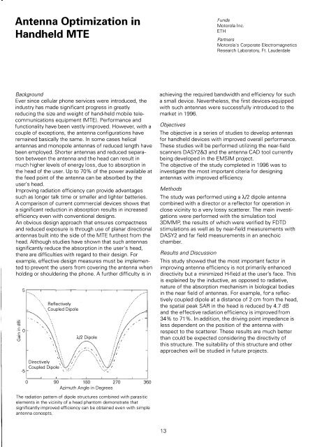
The radiation pattern of dipole structures combined with parasitic<br />
elements in the vicinity of a head phantom demonstrate that<br />
significantly improved efficiency can be obtained even with simple<br />
antenna concepts.<br />
13