

Optimizing PV Systems July 2014.pdf

Create successful ePaper yourself
Turn your PDF publications into a flip-book with our unique Google optimized e-Paper software.
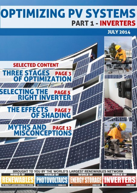
OPTIMIZING <strong>PV</strong> SYSTEMS<br />
PART 1 - INVERTERS<br />
JULY 2014<br />
SELECTED CONTENT<br />
THREE STAGES PAGE 3<br />
OF OPTIMIZATION<br />
ELECTING THE PAGE 5<br />
RIGHT INVERTER<br />
THE EFFECTS PAGE 7<br />
OF SHADING<br />
MYTHS AND PAGE 12<br />
MISCONCEPTIONS
OPTIMIZING <strong>PV</strong> SYSTEMS<br />
BY GREG SMITH, SENIOR TECHNICAL TRAINER, SMA AMERICA<br />
As a solar professional, it’s<br />
important to carefully<br />
consider the photovoltaic (<strong>PV</strong>)<br />
design that will generate the<br />
highest return on investment<br />
(ROI). While the specifics may<br />
differ between residential<br />
and commercial systems, the<br />
themes are almost always the<br />
same: fast install and fast<br />
payback. However, the really<br />
savvy <strong>PV</strong> companies are<br />
starting to consider more<br />
factors, such as <strong>PV</strong> system<br />
optimization, which will help<br />
keep them profitable for a<br />
long time.<br />
Optimized and properly<br />
maintained <strong>PV</strong> systems have a<br />
much higher rate of return and<br />
produce more energy over the<br />
lifetime of the plant. However,<br />
there is much more to<br />
optimizing a <strong>PV</strong> system than<br />
just simple string sizing. The<br />
1 Optimzing <strong>PV</strong> <strong>Systems</strong> eFeature | <strong>July</strong> 2014<br />
right inverter choice can make<br />
the difference between a<br />
worry-free install and an<br />
operations and maintenance<br />
(O&M) nightmare. The largest<br />
integrators in North America<br />
are realizing that there is no<br />
one-size-fits-all inverter<br />
solution and that they must<br />
expand their product<br />
portfolios if they are going to<br />
extract every last watt-perhour<br />
from their systems to<br />
gain better ROI.<br />
WHAT DOES <strong>PV</strong><br />
OPTIMIZATION MEAN?<br />
<strong>PV</strong> plant optimization means<br />
different things to different<br />
people. To some, it is the<br />
number of modules they can<br />
fit on a string, or AC combiner<br />
bus bar calculations for large<br />
commercial rooftop projects.<br />
Others focus on the inverter<br />
choice: central or string<br />
inverter, string or micro<br />
inverter. Or, perhaps they are<br />
considering using DC<br />
optimizers. For many, “<strong>PV</strong><br />
plant optimization” refers to<br />
the ROI of the installed<br />
system.<br />
According to Andy Black, solar<br />
financial analyst and CEO of<br />
California-based OnGrid<br />
Solar, <strong>PV</strong> system owners can<br />
now get a very close estimate<br />
when they want to know how<br />
long it will take to recoup their<br />
investment. Black said, “…the<br />
payback question can now be<br />
givenaseriousanswer,backed<br />
by solid math and<br />
accounting.”1 Basically, the<br />
math involves comparing the<br />
savings on an electric bill yearby-year<br />
to the amount of the<br />
loan taken out for the <strong>PV</strong> plant.<br />
Although it sounds easy<br />
enough, the system payback<br />
www.worldofphotovoltaics.com
OPTIMIZING <strong>PV</strong> SYSTEMS - PART 1: INVERTERS<br />
speed depends heavily on a few moving<br />
targets: local weather conditions, utility rates<br />
and solar rebates and incentives, just to name a<br />
few.<br />
THREE STAGES OF OPTIMIZATION<br />
There are basically three different stages of <strong>PV</strong><br />
system optimization, beginning at system<br />
design, continuing through installation and<br />
ending with scheduled operation and<br />
maintenance for the life of the plant.<br />
1. DESIGN<br />
The design stage includes selecting the right<br />
inverter, designing the array, performing a site<br />
survey and talking to the customer. It is very<br />
important to understand the customer’s needs<br />
and consider what is optimal for them. Do they<br />
value the public image benefit of offsetting all<br />
of their power use? Or, perhaps your customer<br />
would like a high ROI, which may mean a<br />
smaller "peak $/kWh" shaving system. By<br />
identifying their key drivers and then<br />
considering site-specific limitations, an<br />
integrator can make an informed decision<br />
about technology choice.<br />
Careful consideration must also be given to<br />
array and inverter access for future servicing.<br />
Array layout is influenced by local jurisdiction<br />
requirements, building and electrical code<br />
standards and often old-fashioned tribal<br />
knowledge. Residential and commercial<br />
installations require preventative<br />
maintenance for worry-free operation, with<br />
vegetation management, rodent control and<br />
visual inspections just a few things to take into<br />
account. Inverter installation manuals usually<br />
include a preventative maintenance section<br />
that includes periodicity.<br />
String sizing is a necessary practice when<br />
designing arrays for string and central<br />
inverters. Properly designed systems will<br />
ensure the following thresholds are achieved:<br />
adequate <strong>PV</strong> start voltages, inverter operation<br />
within the maximum power point window and<br />
maximum system voltage below either 600 V<br />
3 Optimzing <strong>PV</strong> <strong>Systems</strong> eFeature | <strong>July</strong> 2014 www.worldofphotovoltaics.com
www.worldofphotovoltaics.com<br />
or 1,000 V DC. Designers use their string sizing<br />
tools to keep these voltage milestones in<br />
check; however, recent studies have shown<br />
that operating the inverter close to the<br />
maximum power point (MPP) voltage could<br />
actually be more efficient than operating at<br />
MPP voltage.<br />
2. INSTALLATION<br />
The installation phase, which often has a<br />
checks and balances effect on the previous<br />
stage, includes wiring methods, installation<br />
best practices (proper torque, wiring<br />
selection, etc.), code adherence and baseline I-<br />
V traces (mostly for commercial applications).<br />
While these are all important facets of the<br />
process, proper system commissioning is<br />
critical. Commissioning a small residential<br />
system usually is no problem, even for the<br />
novice installer, but the thought of<br />
commissioning a 100 kW or multi-megawatt<br />
installation using hundreds of string inverters<br />
could intimidate even a seasoned installer.<br />
While there are a few inverter manufacturers<br />
who offer commissioning services for these<br />
larger systems, the underlying message is<br />
clear: slower is faster. Every inverter<br />
installation manual has a section on<br />
commissioning the unit. Also available is the<br />
North American Board of Certified Energy<br />
Practitioners (NABCEP) Photovoltaic Installer<br />
Resource Guide2, which helps <strong>PV</strong> industry<br />
professionalsthroughtheprocessof<strong>PV</strong>system<br />
design, installation and commissioning, for<br />
free download on the NABCEP website.<br />
Following a clear, repeatable, step-by-step<br />
process ensures a safe environment when the<br />
inverters are brought online.<br />
3. OPERATION AND MAINTAINANCE<br />
This final stage consists of a well thought-out<br />
and properly executed O&M plan that will<br />
ensure a worry-free and profitable <strong>PV</strong> system<br />
for decades to come. Larger arrays may require<br />
routine inspections using I-V curve and<br />
Optimzing <strong>PV</strong> <strong>Systems</strong> eFeature | <strong>July</strong> 2014<br />
4
OPTIMIZING <strong>PV</strong> SYSTEMS - PART 1: INVERTERS<br />
thermal temperature tools. These periodic<br />
audits can provide useful trend analysis<br />
reports to identify and prevent future<br />
problems. Equipment servicing per<br />
manufacturer’s recommendations is a must<br />
and vegetation management for larger<br />
arrays could become part of a scheduled<br />
maintenance routine.<br />
NABCEP Certified <strong>PV</strong> Installer Brian Mehalic,<br />
project engineer for O2 Energies in North<br />
Carolina, has over a decade of <strong>PV</strong> experience<br />
and has commissioned hundreds of<br />
residential and large commercial plants.<br />
With more than 23 MW of <strong>PV</strong> qualityassurance<br />
inspections, Mehalic highly<br />
recommends a sensible O&M strategy for<br />
larger <strong>PV</strong> systems. When teaching the Solar<br />
Energy International (SEI) operations and<br />
maintenance course3, he emphasized the<br />
need to, “Schedule early follow up...one<br />
month, 90 days, whatever is necessary, and<br />
keep an eye on the production early on.<br />
Failures/issues tend to follow a bathtub<br />
curve.”<br />
All three stages are important for the longterm<br />
health of the <strong>PV</strong> system, but most<br />
questions arise during the design stage - and<br />
it is easy to understand why. It is the stage<br />
most rooted in tradition, tribal knowledge or<br />
perhaps even ignorance of alternatives. Most<br />
solar industry professionals do not want to<br />
debate the best inverter topology, but it is<br />
definitely worth spending some time<br />
discussing.<br />
INVERTER SELECTION<br />
When considering inverter selection, one<br />
must ask, “What problem am I trying to<br />
solve?” Generally speaking, for residential<br />
applications there are two main categories of<br />
inverters: string inverters and module-level<br />
power electronics (MLPE). Commercial<br />
applications favor string inverters and/or<br />
central inverters, with the latter typically<br />
chosen for large utility-scale applications.<br />
Each has its strengths and weaknesses and<br />
there is no one-size-fits-all approach if you<br />
value a positive ROI and consider the O&M<br />
involved with the system.<br />
While there are commercial installations<br />
using MLPE, typically they do not yield a<br />
reasonable ROI since the higher capital<br />
expenses are often not offset by the O&M<br />
system costs. In the end, more profit can be<br />
madeoverthelifetimeofthe<strong>PV</strong>systemusing<br />
a string inverter for large commercial<br />
applications rather than an MLPE.<br />
STRING INVERTERS<br />
String inverters are well known in the<br />
industry and have been the de facto standard<br />
for <strong>PV</strong> installations for decades. There are<br />
three topologies associated with string<br />
inverters: low frequency transformer, high<br />
frequency transformer and transformerless,<br />
with the latter being the lightest and most<br />
efficient of the three. Leading string<br />
inverters are easy to maintain, require little<br />
O&M and have become lighter, more reliable<br />
and more efficient as the years have passed.<br />
String inverters are named for the process of<br />
connecting a string of modules in a series to<br />
increase the system voltage. Depending on<br />
the size of the inverter, multiple strings are<br />
connected in parallel to increase the total<br />
currentofthe<strong>PV</strong>array,thusincreasingtheDC<br />
power of the array.<br />
MODULE-LEVEL-POWER ELECTRONICS<br />
This broad category includes devices that are<br />
mounted onto or behind the solar modules<br />
and consist of two different types of<br />
converters: micro inverters and DC<br />
optimizers. Both types of devices are<br />
connected to an individual module, but they<br />
differ in their conversion process.<br />
Micro inverters convert the DC directly into<br />
ACatthemodulelevel,usuallyeither240Vor<br />
208 VAC. This power is then sent to the main<br />
breaker in the installation via each<br />
5 Optimzing <strong>PV</strong> <strong>Systems</strong> eFeature | <strong>July</strong> 2014 www.worldofphotovoltaics.com
neighboring micro inverter. The inverters are connected together either by using a<br />
trunkcabling system or by daisy chain.<br />
Optimizers do not convert the <strong>PV</strong> energy directly into AC, but rather perform a DC-to-DC<br />
optimization so that the attached string inverter has a constant voltage to work with for the<br />
DC-to-AC conversion.<br />
AC modules are a type of micro inverter that is directly connected to the module junction box<br />
and eliminates exposed DC conductors, but theydo not have the market penetration of the<br />
micro inverters or optimizers.<br />
Each type of MLPE provides a more granular level of <strong>PV</strong> system output than a string inverter<br />
since it is able to capture module-level data and present it to the end user. Some<br />
manufacturers offer this module-level monitoring for a nominal charge while others offer it<br />
for free.<br />
With so many inverter options available, it can be daunting to sift through the<br />
technicalspecifications of each topology to determine which one is best for a particular<br />
application. There are only a handful of inverter manufacturers that sell string, central and<br />
microinvertersandthereforeareintheuniquepositiontoactasasolarconsultantbyguiding<br />
the discussion to which inverter is best for the given application.<br />
Generallyspeaking,thethreetypesofinverterseachhavetheirownbenefitsandfitverywell<br />
into their respective applications when considering the following factors:<br />
As the table indicates, there are a few string inverters on the market that can actually handle<br />
these complex installation factors. Let’s take a look at some advances in string inverter<br />
technology that mitigate some of the concerns installers have about using them in<br />
www.worldofphotovoltaics.com Optimzing <strong>PV</strong> <strong>Systems</strong> eFeature | <strong>July</strong> 2014 6
OPTIMIZING <strong>PV</strong> SYSTEMS - PART 1: INVERTERS<br />
challenging <strong>PV</strong> installations.<br />
THE EFFECTS OF SHADE<br />
Historically, there were a few challenges with<br />
string inverters, most notably the issue of<br />
shade. Partial shade affects <strong>PV</strong> array output<br />
and can be caused by an existing dormer,<br />
chimney or other roof protrusion. It also can go<br />
unnoticed on commissioning day and show up<br />
years later as a nearby sapling matures into a<br />
mighty oak.<br />
The market has demanded tools to help deal<br />
with the issue of shade and several<br />
manufacturers—such as Solmetric, Suneye<br />
and Solar Pathfinder, just to name a few - have<br />
responded. These companies make analysis<br />
tools called I-V curve tracers that are quickly<br />
becoming a valuable tool for installers.<br />
I-V curve tracers are able to graphically show<br />
the effects of shade on a <strong>PV</strong> array by plotting<br />
the corresponding current versus voltage (I-V)<br />
values onto a chart, or curve. These useful<br />
devices are more affordable than they once<br />
were and are in the toolbox of every serious <strong>PV</strong><br />
installer. The curves can be saved<br />
electronically or even printed out. Regardless<br />
ofwheretheshadeisonanarray,theeffectsare<br />
always seen on the upper end of the I-V curve,<br />
as seen in this diagram from a Solmetric<br />
IV-600A:<br />
produced.<br />
MPP TRACKERS FOR<br />
ISSU<br />
The issue of static partial shading can be inescapable<br />
without restricting the size of the array. The challenge of<br />
shading presents itself particularly on commercial<br />
buildings with obstructions such as air conditioning units<br />
and irregularly shaped roofs, causing output losses of<br />
up to as much as 25%. Output is reduced if shading<br />
occurs on any part of an array, even if all other modules<br />
remain in direct sunlight. How much the output is<br />
reduced depends on how the array is configured. This<br />
is because modules are connected in series and<br />
shading on one or more of them will cause variances in<br />
the MPP voltage from the modules. Normally the<br />
inverter cannot find the optimal MPP point as it is stuck<br />
on the global MPP, but instead the new local MPP<br />
would generate more power.<br />
When one of Germany’s leading manufacturers of<br />
natural medicines, SALUS GmbH, took the decision in<br />
May to add a further 300kW to their existing system,<br />
installers at Elektrotechnik Pichler were presented with<br />
the challenge of shading. The 96m 2 east/west roofmounted<br />
system, which is located on the hydroelectric<br />
plant, has a large number of chimneys on the roof, so<br />
multistring inverters were required.<br />
The installations use in total 24 string inverters including<br />
22 Fronius IG Plus inverters plus 2 new Fronius Symos<br />
to tackle the shading issues. The Fronius Symo<br />
inverters total 14.8 kW of the installation and were<br />
selected for their flexibility due to the high system<br />
voltage (1,000 V), wide input voltage range (150 V to<br />
800 V) and twin MPP trackers.<br />
Shading causes peaks on the I-V curve (shown<br />
in the diagram below) and each one is a<br />
potential maximum power point that the<br />
string inverter could track off on. The local<br />
peaks represent lower power output while the<br />
global peak represents the point on the I-V<br />
curve where maximum available power is<br />
Separating an array into two segments, each on their<br />
own MPPT, as has been done at SALUS GmbH,<br />
increases system harvesting. This is because shaded<br />
modules no longer have to be connected in the same<br />
string as those that are fully exposed - which keeps<br />
MPP performance in the non-shaded array high -<br />
Fronius UK Ltd | Maidstone Road | Kingston,<br />
Tel: +44 (0) 1908 512 300 | Fax: +44 (0) 1<br />
7 Optimzing <strong>PV</strong> <strong>Systems</strong> eFeature | <strong>July</strong> 2014 www.worldofphotovoltaics.com
PARTIAL SHADING<br />
ES<br />
therefore maximising output. This eliminates the need<br />
for an additional inverter (with associated labour time<br />
and costs) to do effectively the same job. What further<br />
enhances the benefits of the two MPP trackers in the<br />
Fronius Symo is the very broad voltage range of their<br />
input, allowing connection of highly asymmetric<br />
configurations. This enables the system designer to<br />
solve most shading issues. In some cases even a 1:9<br />
ratio between MPPT1 and MPPT2 is possible.<br />
To generate maximum yield, MPPT performance is of<br />
critical importance. The Fronius Symo offers a new<br />
MPP tracking algorithm which dynamically adapts its<br />
behaviour when searching for the optimal operating<br />
point. This Dynamic Peak Manager allows the inverter<br />
to deliver the maximum output in all circumstances.<br />
What’s particularly impressive about this is that it<br />
automatically checks the entire characteristic at regular<br />
intervals to ensure it can always find the maximum<br />
operating point, even when partially shaded therefore<br />
no longer are there hidden Local MPP points. The two<br />
MPP trackers in the Fronius Symo work completely<br />
independently of each other, which guarantees<br />
maximum power and yields, even under difficult<br />
conditions such as (partial) shade, foggy weather,<br />
module failure and so on.<br />
The east/west system at SALUS that took just 2 days to<br />
install is set to produce 12,070kWh per year, of which<br />
800 – 900kW will be used for manufacturing natural<br />
medicines. Bernard Pichler, installer of the 100% selfconsumption<br />
system, found a solution for the shaded<br />
areas of the roof that would not only maximize yield, but<br />
save time and money and therefore increase<br />
profitability of the installation.<br />
Milton Keynes | MK10 0BD, United Kingdom<br />
908 512 329 | http://www.fronius.co.uk<br />
www.worldofphotovoltaics.com<br />
Shading analysis performed during the initial<br />
site survey can help predict the impact of<br />
shade on annual inverter yield and help<br />
identify any future surprises that could affect<br />
<strong>PV</strong> plant production. Partial shading has a<br />
direct impact on plant optimization, and, in the<br />
end, it costs the homeowner some ROI, but not<br />
as much as was once believed.<br />
While the best way to deal with partial shade is<br />
to avoid it altogether, partial shading can now<br />
be a non-issue for the industry, thanks to<br />
advancements in inverter technology.<br />
Multiple maximum power point trackers<br />
(MPPT) and shade-accommodating MPPT<br />
algorithms all but eliminate the effects of<br />
partial shade and multiple roof orientation<br />
concerns.<br />
MAXIMUM POWER POINT TRACKING<br />
CHANNELS<br />
Traditionally, string inverters had a single<br />
MPPT input, or channel, with which the<br />
inverter microprocessor would vary the<br />
inverter’s internal resistance to act as a load on<br />
the array. As the voltage went down, the<br />
current went up, and vice versa, all while the<br />
inverter was ensuring it was tracking the<br />
maximum voltageversa, all while the inverter<br />
was ensuring it was tracking the maximum<br />
voltage and maximum current on the I-V curve,<br />
which would produce the maximum available<br />
power from the <strong>PV</strong> array.<br />
Several sting inverter manufacturers have now<br />
designed products that have dual MPPT<br />
channels for residential and some commercial<br />
applications. The big advantage of this feature<br />
is that individual strings at different<br />
orientations can now be connected to its own<br />
Optimzing <strong>PV</strong> <strong>Systems</strong> eFeature | <strong>July</strong> 2014<br />
8
OPTIMIZING <strong>PV</strong> SYSTEMS - PART 1: INVERTERS<br />
varying voltages and currents. Additionally, a partially shaded string will have no effect on<br />
the unshaded string since they are electrically isolated and tracked by their own MPPT.<br />
SHADE-ACCOMMODATING MPPT<br />
One of the biggest leaps in inverter technology is shade-accommodating MPPT algorithms.<br />
These algorithms perform an I-V sweep of the <strong>PV</strong> array, much like an I-V curve tracer, and then<br />
shift the MPP from a lower array power local peak up to the maximum power global peak.<br />
For those who prefer MLPE, module-level strategies can also be deployed to address partial<br />
shading, but they come at a higher cost.<br />
MODULE-LEVEL POWER ELECTRONICS IN RESIDENTIAL AND COMMERCIAL APPLICATIONS<br />
There are compelling reasons to use MLPE, even in applications where other topologies<br />
would make better sense with respect to ROI. Micro inverters and optimizers share these<br />
favorable attributes for some business models:<br />
For installers in states that do not offer attractive rebate structures, micro inverters allow<br />
them to add on to a residential <strong>PV</strong> system every year or so, as the homeowner is able to afford<br />
the expansion.<br />
Other installers, such as Nathan Charles of Pennsylvania-based Paradise Energy Solutions,<br />
cite high employee turnover rates and costly labor training for string inverters as reasons<br />
why they choose micro inverters. According to Charles, he can have a fully trained crew ready<br />
to deploy and install micro inverter systems within a matter of weeks. “As a whole, micro<br />
inverters require less training and personal protection equipment,” he said.<br />
For Charles, “The failure rate of micro inverters is an acceptable risk.” He informs his<br />
customers, who might be monitoring their module-level data on a daily basis, that failed<br />
units will be replaced annually and not when each one fails. “A failed inverter costs the<br />
homeowner about $30 per year,” he added, “which isn’t enough to justify rolling a truck.”<br />
Module-level monitoring does come in handy for quickly finding defective inverters and for<br />
locating ground faults caused by rodents. Ground fault localization is a time-consuming<br />
practice that is virtually eliminated when using MLPE. Knowing how many inverters will be<br />
replaced and which tools will be required for servicing are advantages of using MLPE.<br />
11 Optimzing <strong>PV</strong> <strong>Systems</strong> eFeature | <strong>July</strong> 2014 www.worldofphotovoltaics.com
This strategy mitigates the installer’s O&M<br />
costs but it might not be the best solution for<br />
the customer, who paid for the modules and<br />
inverters to work consistently. Those failures<br />
could elevate their monthly utility bills into a<br />
higher tier.<br />
While the argument for MLPE sounds<br />
reasonable on the surface, with benefits<br />
ranging from reducing the effects of partial<br />
shading and soiling to the cost-cutting, preemptive<br />
strikes achieved by using modulelevel<br />
monitoring for O&M and servicing,<br />
MLPE are not the best choice for all systems<br />
and applications and should be applied when<br />
conditions favor their usage.<br />
MYTHS AND MISCONCEPTIONS<br />
There are scientific, peer-reviewed<br />
resources that partly support the claims of<br />
MLPE companies, but when those claims are<br />
given proper scrutiny, many questions and<br />
concerns arise. Here are the top three myths<br />
concerning MLPE:<br />
1. String inverters operate at the lowest<br />
performing module.<br />
A common driver of this myth is the notion<br />
that if a module is shaded by 50 percent, then<br />
the rest of the string output power is reduced<br />
by 50 percent. Here is a common image used<br />
to illustrate this “Christmas tree effect”:<br />
www.worldofphotovoltaics.com Optimzing <strong>PV</strong> <strong>Systems</strong> eFeature | <strong>July</strong> 2014 12
OPTIMIZING <strong>PV</strong> SYSTEMS - PART 1: INVERTERS<br />
In reality, shading 50 percent of one module will<br />
reduce the output of that string by about 13<br />
percent. This loss will usually occur early in the<br />
morning or late in the afternoon when partial<br />
shade is most prevalent. Shading at solar noon<br />
will result in a negative ROI even when MLPE are<br />
used.<br />
Many whitepapers regarding this topic in the<br />
European Photovoltaic Solar Energy Conference<br />
(EU <strong>PV</strong>SEC) library have been reviewed by<br />
industry experts and none support the<br />
Christmastreeeffectwhenmoduleswithbypass<br />
diodes are tested. In fact, shading studies fall<br />
short of discussing and testing different shading<br />
effects on different module technologies. A<br />
particular paper in this library entitled<br />
“Performance Measurement and Monitoring of<br />
Shadow Effects on <strong>PV</strong> <strong>Systems</strong>4” concluded that<br />
shading had less of an effect on thin film than<br />
crystalline solar modules.<br />
2. MLPE have lower O&M and installation costs<br />
than string inverters.<br />
Since every installation is different, this is a<br />
highly subjective claim and one that requires the<br />
installer to perform a cost comparison. Some<br />
manufacturers suggest that the estimated<br />
20-year maintenance and replacement cost for a<br />
7 kW string inverter system is $5,1925 while the<br />
same size micro inverter system, using 30<br />
inverters, only costs $739. However, this<br />
informationdoesnotindicateifthe$739wasfor<br />
oneinverterreplacementorforall30,orhowthe<br />
$5,192 string inverter replacement cost was<br />
derived (that figure is highly dependent upon<br />
inverter manufacturer).<br />
13 Optimzing <strong>PV</strong> <strong>Systems</strong> eFeature | <strong>July</strong> 2014 www.worldofphotovoltaics.com
Whileitmayonlycost$739toreplaceonemicro<br />
inverter, there are still 29 more that will<br />
eventually fail. This inevitability brings the<br />
replacement costs to a much more realistic<br />
number of 30 x $739 = $22,170, assuming the<br />
installerperformedaservicecalltoreplaceeach<br />
failed inverter.<br />
Lower installation costs are another dubious<br />
claim that requires examination for each<br />
installation. Balance-of-system (BOS) costs and<br />
installation times might favor either topology<br />
since there are AC conductors that must be run<br />
down off the roof, there must still be an AC<br />
service disconnect (AHJ dependent) and<br />
optimizer DC home runs must be connected to<br />
an inverter, therefore doubling the amount of<br />
work required for the same size install as a string<br />
inverter.<br />
3. Micro inverters and optimizers generate<br />
significantly more power in shaded areas than a<br />
string inverter.<br />
This claim requires no further research than a <strong>PV</strong><br />
Evolution Labs (<strong>PV</strong>EL) study published in 2012.<br />
Using the NREL test protocol for conducting<br />
experiments on shaded arrays6, the <strong>PV</strong>EL<br />
concludedthatmicroinvertersdoproducemore<br />
energy than string inverters in light, moderate<br />
and heavy shaded conditions by 3.7 percent, 7.8<br />
percent and 12.3 percent, respectively. Since<br />
the overwhelming majority of partially shaded<br />
arrays in residential installations fall into the<br />
light and moderate categories, the heavy<br />
shaded array value can be discarded. Most<br />
respectable designers would not consider<br />
installing a heavy shaded array anyway and it<br />
would be very difficult to secure financing for<br />
this type of system.<br />
Optimizers make the same kind of claim but use<br />
a different number before getting to the core of<br />
their extra yield. For example, a leading<br />
optimizer company, citing a similar NREL<br />
study7, claims “up to 25 percent more energy<br />
and 99.5 percent (max) efficiency” for their DC<br />
optimizer system. The 25 percent figure is, of<br />
course, the heavy shaded result, but they do<br />
www.worldofphotovoltaics.com Optimzing <strong>PV</strong> <strong>Systems</strong> eFeature | <strong>July</strong> 2014<br />
14
Now THIS is a G<br />
Introducing the 3 Phase String<br />
EFFICIE<br />
Now there’s<br />
projects. We<br />
with many ap<br />
efficiency an<br />
Backed by th<br />
trust, the AE<br />
distributed i<br />
AE 3TL<br />
• Over 3 GW<br />
• Industry-le<br />
• UL 1741 Ce<br />
• kW Rating<br />
• Basic and<br />
www.advan
ame Changer<br />
Inverter from Advanced Energy<br />
90º<br />
NT & FLEXIBLE <strong>PV</strong> SYSTEM APPLICATIONS<br />
CAR PORTS<br />
ROOFTOPS<br />
a plug and play solution for a wide range of commercial-scale solar <strong>PV</strong><br />
ighing in at only 108 pounds, the AE 3TL is easy to install and compatible<br />
plications and the most challenging system designs. With industry leading<br />
d reliablity, it maximizes energy yield and minimizes maintenance.<br />
e exceptional service, support, and industry leadership you’ve come to<br />
3TL is innovation you can bank on. Invest in the game changing power of<br />
nverters from Advanced Energy.<br />
AT A GLANCE<br />
installed<br />
ading CEC efficiency rating of 98%<br />
rtified<br />
s from 12-23, solutions for 600 V and 1000 V applications<br />
premium monitoring options<br />
GROUND MOUNTS<br />
SHIFT YOUR PERSPECTIVE. WE’LL CHANGE HOW YOU LOOK AT SOLAR.<br />
ced-energy.com/ae3tl I sales.support@aei.com I 877.312.3832
OPTIMIZING <strong>PV</strong> SYSTEMS - PART 1: INVERTERS<br />
claim “1.9 percent more energy than the<br />
string inverter” in the more likely scenario<br />
of light partial shade.<br />
Let’s put this 1.9 percent recovery value into<br />
perspective, starting with this <strong>PV</strong> industry<br />
universal truth: All inverters fail - eventually.<br />
Installers have to weigh whether the<br />
benefits of MLPE make up for the fact that<br />
they will have to go up on the roof at some<br />
point to replace all those devices. Optimizer<br />
systems are more involved because the<br />
installer will also have to replace the<br />
inverter.<br />
Taking the optimizer study at face value and<br />
assuming the average utility cost of $.12 per<br />
kWh, these variables can be used to estimate<br />
howmuchmoneytheoptimizersystemsaves<br />
on an annual basis for a 6,000 W system. The<br />
sobering conclusion illustrated below was<br />
derived from just a quick look at the<br />
production claims.<br />
In 2010, the Fraunhofer-Institute for Solar<br />
Energy <strong>Systems</strong> ISE submitted a whitepaper<br />
to the 25th annual EU <strong>PV</strong>SEC entitled, “Light<br />
and Shadow – When is Tracking MPP at the<br />
Module Level Worthwhile?”8 Gains in<br />
energy production due to soiling, shading,<br />
module mismatch and other factors were<br />
tested and the results are summed up in the<br />
following graph. The influencing factors are<br />
labeled on the outside of the wheel. The red<br />
hashed area represents the return for string<br />
MPPT, while the blue hashed areas are for<br />
module-level MPPT.<br />
15 Optimzing <strong>PV</strong> <strong>Systems</strong> eFeature | <strong>July</strong> 2014 www.worldofphotovoltaics.com
The conclusion had this to say:<br />
“Generally, the use of MPP tracking at the<br />
modulelevel,inordertorecoverlossesdueto<br />
partial shading, is only profitable in very few<br />
cases for a medium level of partial shading.”<br />
The values for yield recovery in partially<br />
shaded conditions were almost identical to<br />
the NREL study. There are sections on the<br />
wheel where the blue shaded areas are<br />
outside the red areas and these influencing<br />
factorsareinfavorofMLPE,astheyshouldbe.<br />
The authors are revealing this truth but are<br />
also pointing out that those factors may not<br />
be worth while for MLPE with respect to the<br />
modest gains. This is not to say MLPE do not<br />
have their place since the authors (indirectly)<br />
validated my initial premise: there is no onesize-fits-all<br />
in this industry; every situation<br />
is different.<br />
www.worldofphotovoltaics.com<br />
FINAL THOUGHTS<br />
<strong>Optimizing</strong> <strong>PV</strong> systems has changed over the<br />
years and, as the technology evolves, perhaps<br />
the industry will adopt other ways of enhancing<br />
these systems. Whether it is string, micro,<br />
optimizer or central inverter, people will use<br />
what makes sense to their business models<br />
and/or what they feel comfortable with.<br />
Technology has changed this industry<br />
tremendously in the last 10 years and the good<br />
news is that the best has yet to come. The better<br />
news is that there is plenty of room in this<br />
industry for everyone.<br />
Optimzing <strong>PV</strong> <strong>Systems</strong> eFeature | <strong>July</strong> 2014 16
www.worldofphotovoltaics.com Optimzing <strong>PV</strong> <strong>Systems</strong> eFeature | <strong>July</strong> 2014 20
REFERENCE LIST<br />
1. Black, Andy, “What’s the Payback? How to calculate the<br />
return on your solar electric system investment before you<br />
buy,” OnGrid Solar.net, 2006.<br />
2. Brooks, Bill, and Dunlop, James, “NABCEP Photovoltaic<br />
Resource Guide,” August 2012.<br />
3. Tools and Techniques for Operations and Maintenance,<br />
Solar Energy International.<br />
4. Del Buono, Armani, Potz, Cattani, and Sparber, “Perfor<br />
mance Measurements and Monitoring of Shadow Effects<br />
on <strong>PV</strong> <strong>Systems</strong>,” EU <strong>PV</strong>SEC Proceedings, September 2008.<br />
5. Mohd, A, “The Evolution of <strong>PV</strong> Solar Power<br />
Architectures: A Quantitative Analysis of Micro Inverters’<br />
Performance vs. Conventional Inverters,” EU <strong>PV</strong>SEC<br />
Proceedings, September 2011.<br />
6. National Renewable Energy Laboratory, “Photovoltaic<br />
Shading Testbed for Module-Level Power Electronics.”<br />
7. SolarEdge, “Performance of <strong>PV</strong> Topologies under<br />
Shaded Conditions.”<br />
8. Rogalla, Burger, Goeldi, and Schmidt, “Light and<br />
Shadow – When is MPP-Tracking at the Module Level<br />
Worthwhile?” EU <strong>PV</strong>SEC Proceedings, September 2010.
19 Optimzing <strong>PV</strong> <strong>Systems</strong> eFeature | <strong>July</strong> 2014 www.worldofphotovoltaics.com
Powered by TCPDF (www.tcpdf.org)