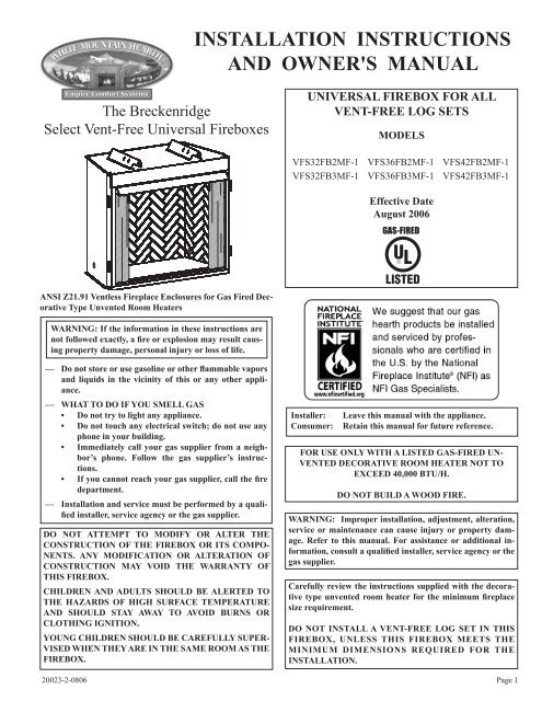
INSTALLATION INSTRUCTIONS AND OWNER'S MANUAL
20023-2-0806 VFS(32,36,42)FB(O,2) - White Mountain Hearth
20023-2-0806 VFS(32,36,42)FB(O,2) - White Mountain Hearth

You also want an ePaper? Increase the reach of your titles
YUMPU automatically turns print PDFs into web optimized ePapers that Google loves.
TABLE OF CONTENTS<br />
SECTION<br />
PAGE<br />
Important Safety Information .................................................................................................3<br />
Introduction ............................................................................................................................3<br />
Clearances ..............................................................................................................................4<br />
Firebox Installation Instructions ......................................................................................... 4-7<br />
Installing Hood ................................................................................................................... 7-8<br />
Gas Line Connection .............................................................................................................8<br />
Optional Single Speed Blower Installation Instructions .................................................. 9-11<br />
Junction Box Wiring Installation Instructions ......................................................................12<br />
Maintenance .........................................................................................................................12<br />
Parts List .............................................................................................................................13<br />
Parts View .............................................................................................................................14<br />
How to Order Repair Parts ...................................................................................................14<br />
Accessories ..................................................................................................................... 15-16<br />
Page 2<br />
20023-2-0806
IMPORTANT SAFETY INFORMATION<br />
The installation must conform with local codes or, in<br />
the absence of local codes, with the National Fuel Gas<br />
Code, ANSI Z223.1 (latest edition) and to the National<br />
electrical Code, ANSI/NFPA70 (latest edition).<br />
NOTE: Installation and repair should be done by a qualified<br />
service person. The appliance should be inspected<br />
before use and at least annually by a qualified service<br />
person. More frequent cleaning may be required due to<br />
excessive lint from carpeting, bedding material, etc. It<br />
is imperative that control compartment, burners and<br />
circulating air passageways of the appliance be kept<br />
clean.<br />
This Empire Comfort Systems, Inc. firebox and its<br />
components have been tested and will operate safely when<br />
installed in accordance with this installation manual.<br />
Read all instructions before starting installation, then<br />
follow these instructions carefully during installation<br />
to maximize firebox benefit and safety. Report to your<br />
dealer any parts damaged in shipment.<br />
The Empire Comfort Systems, Inc. warranty will be<br />
voided by, and Empire Comfort Systems, Inc. disclaims<br />
any responsibility for the following actions:<br />
- Installation of any damaged firebox.<br />
- Modification of the firebox or any of the components<br />
parts thereof.<br />
Any safety screen or guard removed for servicing an<br />
appliance must be replaced prior to operating the appliance.<br />
Provide adequate combustion and ventilation<br />
air.<br />
The flow of combustion and ventilation air MUST NOT<br />
be obstructed.<br />
Provide adequate clearance around air openings into<br />
the combustion chamber and adequate accessibility<br />
clearance for servicing and proper operation. NEVER<br />
obstruct the front opening of the appliance.<br />
- Installation other than as instructed by Empire<br />
Comfort Systems, Inc.<br />
- Installation and/or use of any component part or<br />
accessory not approved by Empire Comfort Systems,<br />
Inc. in combination or assembly with a Empire<br />
Comfort Systems, Inc. firebox, not withstanding any<br />
independent testing laboratory or other third party<br />
approval of such component part or accessory.<br />
Any such action may create a possible fire hazard.<br />
Consult your local building codes.<br />
Firebox Screen.<br />
The firebox screen must be in place when the firebox is<br />
operating.<br />
INTRODUCTION<br />
Instructions to Installer<br />
1. Installer must leave instruction manual with owner after<br />
installation.<br />
2. Installer must have owner fill out and mail warranty card<br />
supplied with firebox.<br />
3. Installer should show owner how to start and operate log set<br />
that is installed into firebox.<br />
Important<br />
All correspondence should refer to complete Model Number,<br />
Serial Number.<br />
Notice: During initial firing of this firebox with a log set installed, its<br />
paint will bake out, and smoke will occur. To prevent triggering of<br />
smoke alarms, ventilate the room in which the unit is installed.<br />
Qualified Installing Agency<br />
Installation and replacement of gas piping, gas utilization<br />
equipment or accessories and repair and servicing of equipment<br />
shall be performed only by a qualified agency. The term "qualified<br />
agency" means any individual, firm, corporation or company<br />
which either in person or through a representative is engaged in<br />
and is responsible for (a) the installation or replacement of gas<br />
20023-2-0806<br />
piping or (b) the connection, installation, repair or servicing of<br />
equipment, who is experienced in such work, familiar with all<br />
precautions required and has complied with all the requirements<br />
of the authority having jurisdiction.<br />
State of Massachusetts: The installation must be made by<br />
a licensed plumber or gas fitter in the Commonwealth of<br />
Massachusetts. The state of Massachusetts requires that a<br />
flexible appliance connector cannot exceed three feet in<br />
length.<br />
Sellers of unvented propane or natural gas-fired supplemental<br />
room heaters shall provide to each purchaser a copy of 527<br />
CMR 30 upon sale of the unit.<br />
In the State of Massachusetts, unvented propane and natural<br />
gas-fired space heaters shall be prohibited in bedrooms and<br />
bathrooms.<br />
The installation must conform with local codes or, in the absence<br />
of local codes, with the National Fuel Gas Code, ANSI Z223.1/<br />
NFPA 54.*<br />
*Available from the American National Standards Institute, Inc., 11 West<br />
42nd St., New York, N.Y. 10036.<br />
Page 3
CLEARANCES<br />
Sidewall Clearances: The clearance from the inside of the firebox<br />
to perpendicular combustible side wall should not be less than<br />
6". See Figure 1.<br />
Firebox Side and Back Clearances: The firebox outer casing side<br />
and back flanges are zero clearance to combustibles.<br />
Top Framing and Finishing: Combustible framing may rest on<br />
top of standoffs. Combustible finishing materials may extend<br />
to the top standoff screws on the front edge of the outer wrap.<br />
See Figure 2.<br />
Ceiling Clearances: The ceiling height should not be less than 42"<br />
from the top of the hood. See Figure 3.<br />
Mantel Clearances: Vent free firebox models must use the hood<br />
supplied with the firebox, or one of the optional hood kits<br />
available for each model. If a combustible mantel is installed,<br />
it must meet the clearance requirements detailed below.<br />
Grate Clearance: The minimum clearance between the front legs<br />
of the grate and front edge of the firebox is 2".<br />
Leave at least 36" clearance from the front of the firebox.<br />
2 X 4<br />
HEADER<br />
FRONT FACE (SIDE)<br />
ST<strong>AND</strong> OFF<br />
FIREBOX<br />
(TOP VIEW)<br />
Figure 1<br />
3”<br />
MAX.<br />
45°<br />
6”<br />
PERPENDICULAR<br />
SIDE WALL<br />
COMBUSTIBLE<br />
MATERIALS ALLOWED<br />
IN SHADED AREAS<br />
COMBUSTIBLE<br />
FINISHED WALL<br />
OR MANTEL<br />
FINISH WITH TRIM KIT OR<br />
NON-COMBUSTIBLE MATERIAL<br />
AS DESIRED.<br />
CEILING<br />
84”<br />
MIN.<br />
(CEILING TO FLOOR)<br />
24 ½”<br />
42”<br />
MIN.<br />
(CEILING TO<br />
TOP OF HOOD)<br />
13”<br />
0”<br />
3/8” COMBUSTIBLE<br />
CLEARANCE REQUIRED<br />
FROM TOP EDGE<br />
OF FIREBOX<br />
12”<br />
MAX<br />
10”<br />
MANTEL<br />
10” 8”<br />
COMBUSTIBLES<br />
ALLOWED<br />
22”<br />
6 ½”<br />
20”<br />
5”<br />
18”<br />
3 ½”<br />
16”<br />
2”<br />
14”<br />
3/4”<br />
12 ½”<br />
11 1/2”<br />
MIN.<br />
HOOD<br />
FIREBOX<br />
FIREBOX<br />
FACE<br />
Figure 3<br />
Figure 2<br />
Any vent-free Gas Log Heater must be “For use with approved<br />
ANSI Z21.11.2 unvented room heater.”<br />
Follow and complete the installation instructions of the gas log set<br />
and the requirements of this firebox.<br />
Clearances to combustibles<br />
FIREBOX <strong>INSTALLATION</strong> <strong>INSTRUCTIONS</strong><br />
Check all fittings for leaks before lighting the gas log set.<br />
In planning the installation for the firebox, it is necessary to<br />
determine where the unit is to be installed and whether optional<br />
accessories are desired. Gas supply piping should also be planned<br />
at this time.<br />
A gas shut off must be in this line.<br />
Page 4<br />
20023-2-0806
The firebox can be mounted on any of these surfaces:<br />
1. A flat hard combustible or non-combustible surface.<br />
2. A raised platform of combustible or non-combustible<br />
material.<br />
3. Recessed into the floor as illustrated by Figure 4.<br />
4. Supported under all (4) corners of the firebox so that contact<br />
is made on all four perimeter edges on the bottom of the unit<br />
(Example: Four (4) concrete masonry blocks).<br />
If the firebox is installed directly on carpeting, tile or other<br />
combustible material other than wood flooring, it should be installed<br />
on a metal or wood panel extending the full width and depth of<br />
the unit.<br />
At this point, you should have decided what components to include<br />
in your installation, and where the firebox is to be located. If this<br />
has not been done, stop and consult your dealer for assistance with<br />
this planning.<br />
Planning Your Installation<br />
Accessory kits such as the FBB5 Blower kit, Trim kits, Mantles,<br />
Full Cabinet Mantels, plus other Decorative Frame, Hood, and<br />
Door accessory kits may be installed after the firebox is secured<br />
to the framed opening.<br />
Refer to the instructions provided with each of the optional<br />
accessory kits for proper installation and operation.<br />
Firebox Framing<br />
Firebox framing can be built before or after the firebox is set<br />
in place. Framing should be positioned to accommodate wall<br />
covering and firebox facing material. The firebox framing should<br />
be constructed of 2 x 4 lumber or heavier. The framing headers<br />
may rest on the top of the firebox standoffs. Refer to Figures 5<br />
and 6 for firebox framing dimensions.<br />
SELECT<br />
MODELS<br />
NON-COMBUSTIBLE<br />
FINISHING MATERIAL<br />
TO FIREBOX OPENING<br />
COMBUSTIBLE MATERIALS ALLOWED<br />
Figure 4<br />
Select Vent-Free Firebox Framing Dimensions (in inches)<br />
"A" "B" "C"<br />
Model Framing Height Framing Width Framing Depth<br />
VFS32FB 41 1/2" 35" 23"<br />
VFS36FB 41 1/2" 40" 23"<br />
VFS42FB 41 1/2" 44" 23"<br />
Attention: Add 3-3/4" to "A" Dimension when using flush mantel base.<br />
Framing dimension A includes a three inch clearance for standoffs on firebox.<br />
Figure 5<br />
20023-2-0806<br />
Page 5
FIREBOX <strong>INSTALLATION</strong> <strong>INSTRUCTIONS</strong> (continued)<br />
C<br />
E<br />
SELECT<br />
G<br />
I<br />
A<br />
H<br />
J<br />
F<br />
B<br />
K<br />
D<br />
L<br />
M<br />
REFERENCE<br />
LETTER<br />
SELECT<br />
FLUSH<br />
VFS32 VFS36 VFS42<br />
A 41 1/8" 41 1/8" 41 1/8"<br />
B 34 1/2" 39 1/2" 43 1/2"<br />
C 23 7/16" 23 7/16" 23 7/16"<br />
D 26 3/8" 31 3/8" 35 3/8"<br />
E 38 1/2" 38 1/2" 38 1/2"<br />
F 31" 36" 40"<br />
G 31 3/4" 31 3/4" 31 3/4"<br />
H 2 1/8" 2 1/8" 2 1/8"<br />
I 34" 34" 34"<br />
J 4 1/4" 4 1/4" 4 1/4"<br />
K 7 5/8" 7 5/8" 7 5/8"<br />
L 36 1/2" 39 1/16" 41 1/16"<br />
M 73 1/16" 78 1/16" 82 1/16"<br />
Figure 6<br />
Firebox Dimensions<br />
Page 6<br />
20023-2-0806
FIREBOX <strong>INSTALLATION</strong> <strong>INSTRUCTIONS</strong> (continued)<br />
Locating Firebox<br />
Place firebox in framing opening. Use the four (4) framing brackets<br />
provided on the firebox to attach firebox to framing. Different hole<br />
locations can be used for finishing materials with thicknesses of<br />
3/8", 1/2" and 3/4". Attach these materials with screws provided,<br />
two (2) per framing bracket. See Figure 7.<br />
Framing brackets should fit directly against framing material. Use<br />
at least one (1) nail per bracket to secure in place.<br />
Check squareness of the firebox prior to securing to framed opening.<br />
See Figure 8.<br />
FIREBOX OPENING<br />
CHECK TO SEE<br />
THAT BOX IS SQUARE<br />
PRIOR TO ATTACHING TO<br />
FRAMING<br />
Figure 8<br />
Figure 7<br />
INSTALLING HOOD<br />
A black hood that is furnished with each firebox (or optional hood)<br />
MUST be installed before the firebox is used. Failure to do so may<br />
create a possible fire hazard. The hood is located inside the firebox<br />
on flush face units. If brass, stainless steel, or hammered pewter<br />
hoods are desired, they can be purchased as an option. Attachment<br />
is the same as the standard black hood.<br />
Flush Face Models<br />
1. On flush face models, loosen the two screws (A) holding firebox<br />
top to face panel, then slide the hood flange between the firebox<br />
top and face panel and re-tighten the screws.<br />
2. Install one (1) screw at each end of the hood as shown (C).<br />
Flush Face Models<br />
A<br />
C<br />
A<br />
Louvered Models<br />
Figure 9<br />
C<br />
20023-2-0806<br />
Page 7
The firebox is designed to accept a 3/8-inch gas line for an approved<br />
vent-free gas logset. Have the line installed by a qualified service<br />
person in accordance with all building codes. Consult local building<br />
codes to properly size the gas supply line leading to the 3/8-inch<br />
hook-up at the unit. The state of Massachusetts requires that a<br />
flexible appliance connector cannot exceed three feet in length.<br />
Gas access holes are provided on both sides of the firebox. See<br />
Figure 10. Carefully remove the knockout in the refractory brick<br />
panel using a large standard screwdriver and hammer. First, place<br />
screwdriver in groove next to plug and pry sideways to pop out<br />
main plug. Then remove the remaining concrete in hole with gentle<br />
tapping with ball peen hammer and/or screwdriver. A masonry drill<br />
and bit may also be used to create a clean hole for the gas line to<br />
pass through. See Figure 11.<br />
INSTALLING HOOD (continued)<br />
Extended Hoods<br />
If your non-combustible facing material is over 1" in thickness that will be used to finish this firebox, an extended hood is available that<br />
will extend out 2" farther out into the room. Contact your local dealer for details.<br />
VB4H32BL Standard Black VB4H36BL Standard Black VB4H42BL Standard Black<br />
VB4H32BR Polished Brass VB4H36BR Polished Brass VB4H42BR Polished Brass<br />
VB4H32SS Stainless Steel VB4H36SS Stainless Steel VB4H42SS Stainless Steel<br />
VB4H32HP Hammered Pewter VB4H36HP Hammered Pewter VB4H42HP Hammered Pewter<br />
Finishing<br />
All joints (top, bottom and sides), where the wall or decorative facing material meets the firebox surround should be sealed with a noncombustible<br />
material.<br />
Hearth extensions are recommended, but not required for these fireboxes.<br />
GAS LINE CONNECTION<br />
Check gas type. Use only the gas type indicated on the gas log<br />
set rating plate. If the gas listed on the plate is not your type of<br />
gas supply, DO NOT INSTALL. Contact your dealer for proper<br />
model.<br />
Always use an external regulator for all LP fireboxes to reduce the<br />
supply tank pressure to a maximum of 14" w.c. This is in addition<br />
to the regulator fitted to the log set.<br />
GAS ACCESS HOLES<br />
Figure 10<br />
WARNING: CONNECTION DIRECTLY TO AN<br />
UNREGULATED L.P. TANK CAN CAUSE EXPLOSION.<br />
Install only a ANSI Z21.11.2 vent-free log set into this firebox.<br />
Figure 11<br />
Page 8<br />
20023-2-0806
OPTIONAL SINGLE SPEED BLOWER <strong>INSTALLATION</strong> <strong>INSTRUCTIONS</strong><br />
Attention: Install blower assembly before connecting gas inlet<br />
supply line.<br />
Wiring<br />
The appliance, when installed, must be electrically grounded in<br />
accordance with local codes or, in the absence of local codes,<br />
with the National Electrical Code, ANSI/NFPA 70, if an external<br />
electrical source is utilized. This appliance is equipped with<br />
a three-prong [grounding] plug for your protection against<br />
shock hazard and should be plugged directly into a properly<br />
grounded three-prong receptacle. Do not cut or remove the<br />
grounding prong from this plug. For an ungrounded receptacle,<br />
an adapter, which has two prongs and a wire for grounding, can<br />
be purchased, plugged into the ungrounded receptacle and its wire<br />
connected to the receptacle mounting screw. With this wire completing<br />
the ground, the appliance cord plug can be plugged into<br />
the adapter and be electrically grounded.<br />
A factory installed junction box is located on the lower right<br />
side of the firebox. Wiring must be fed to the junction box<br />
and attached to the receptacle that is provided. From right<br />
side of the firebox, remove the screw securing the junction<br />
box assembly. Leave approximately 6” of wire in the junction<br />
box for connection.<br />
Attach black wire to one side of the receptacle and white wire<br />
to opposite side of receptacle. The ground wire should be attached<br />
to the green (ground) screw.<br />
Install the recepticle into the junction box. Attach cover<br />
plate.<br />
Attention: If installed, do not damage gas inlet supply line<br />
when blower assembly is inserted into firebox. In some cases,<br />
removal the gas inlet supply line may be necessary.<br />
Caution: Label all wires prior to disconnection when servicing<br />
controls. Wiring errors can cause improper and dangerous<br />
operation. Verify proper operation after servicing.<br />
Note: Junction box on right side of firebox must be pre-wired at<br />
time of firebox installation for use with blower assembly. A<br />
standard wall ON/OFF wall switch or optional SCV1 Variable<br />
Speed Control Kit should be installed to activate power<br />
to the Firebox, and control the operation of the FBB5<br />
Blower assembly. It is recommended that installation of the<br />
wiring be performed by a qualified electrician. See Figure<br />
12.<br />
1. If installed, turn OFF gas supply to firebox/gas log.<br />
2. If applicable, turn OFF electric supply to firebox.<br />
CAUTION: ALL WIRING SHOULD BE DONE BY<br />
A QUALIFIED ELECTRICIAN <strong>AND</strong> SHALL BE IN<br />
COMPLIANCE WITH ALL LOCAL, CITY <strong>AND</strong> STATE<br />
BUILDING CODES. BEFORE MAKING THE ELECTRI-<br />
CAL CONNECTION, MAKE SURE THAT MAIN POWER<br />
SUPPLY IS DISCONNECTED. THE APPLIANCE, WHEN<br />
INSTALLED, MUST BE ELECTRICALLY GROUNDED<br />
IN ACCORDANCE WITH LOCAL CODES, WITH THE<br />
NATIONAL ELECTRICAL CODE ANSI/NFPA 70 (LAT-<br />
EST EDITION).<br />
REMOVE HEARTH BRICK, SIDE BRICK,<br />
<strong>AND</strong> BACK BRICK PANEL TO GAIN ACCESS<br />
FOR BLOWER <strong>INSTALLATION</strong>.<br />
CAUTION: MASONRY BRICK PANELS ARE<br />
VERY HEAVY. USE GLOVES <strong>AND</strong> EXTRA<br />
CARE WHEN REMOVING.<br />
NOTE: IF THE BLOWER CAN BE INSTALLED<br />
PRIOR TO FIREBOX <strong>INSTALLATION</strong>, IT MAY<br />
BE EASIER TO REMOVE THE REAR COVER<br />
PLATE PANEL ON THE BACK OF THE FIREBOX<br />
RATHER THAN REMOVING BRICK PANELS.<br />
Figure 13<br />
Select Firebox Models<br />
Figure 14<br />
NOTE: BRICK LINERS REMOVED<br />
TO SHOW <strong>INSTALLATION</strong><br />
OF BLOWER ACCESSORY.<br />
Figure 12<br />
20023-2-0806<br />
Page 9
4. Insert blower assembly into interior, bottom of firebox. Position<br />
blower assembly so that you align the notch on back of<br />
blower assembly with the center screw on firebox back, then<br />
push the blower assembly against firebox back. The blower<br />
wheel must be centered with the back wall of the firebox. The<br />
magnets on the back and bottom of blower assembly will sufficiently<br />
hold blower assembly in place.<br />
Note: For field installation of blower assembly, it may be easier to<br />
remove rear cover panel to install blower. This eliminates<br />
the need to remove brick liner panels, but the blower would<br />
have to be installed prior to installing the firebox into a<br />
wall or chase. See Figure 15.<br />
Figure 15<br />
REAR COVER PANEL MAY BE<br />
REMOVED TO INSTALL BLOWER<br />
REINSTALL COVER AFTER<br />
BLOWER IS INSTALLED<br />
5. Once the blower assembly is in position, locate the plug button<br />
in the top right rear corner of the firebox. Remove the<br />
plug with a standard screwdriver and discard plug.<br />
6. Next, find the fan control switch and wire assembly. Feed the<br />
wires through the hole at the top of the firebox, and secure the<br />
fan control switch with (2) #6 screws provided. See Figure<br />
16.<br />
NOTE: HOOD <strong>AND</strong> BRICK PANELS REMOVED FOR CLARITY<br />
8. One fan control wire will have a 1/4” female terminal that<br />
must be attached to the open terminal on the blower motor.<br />
See Figure 19, Connection A.<br />
9. The other fan control wire has a 1/4” male terminal. Attach<br />
this terminal to the open terminal on the blower power cord.<br />
See Figure 19, Connection B<br />
10. Route the wires away from moving parts of the blower assembly<br />
and retain wires together near the blower motor using<br />
the plastic purse clip provided.<br />
11. To complete the installation, plug the power cord into the<br />
junction box receptacle at the right rear corner of the firebox<br />
outer wrap. See Figure 17.<br />
12. If room permits, the power cord can be located from the outside<br />
of the unit looking through the junction box access hole<br />
(with the junction box removed), then plug up the power cord<br />
before reinstalling the pre-wired junction box.<br />
13. Once all connections are made electrically, it is recommended<br />
that you test the blower fan control operation by turning<br />
on power to the blower (Caution: 110 Volt). Then apply heat<br />
to the fan control switch inside the firebox with a lighter or<br />
match until blower is activated. Once blower is activated,<br />
check for proper operation. Do not place hands near blower<br />
assembly or other wiring while power is on.<br />
14. Replace blower access plate and/or reinstall the brick liner<br />
panels if provided.<br />
15. This completes the installation of the optional FBB5 Blower<br />
kit accessory.<br />
Note: This blower is equipped with a heat activated fan control<br />
switch. Blower will operate when the firebox warms up,<br />
and will turn off automatically when the firebox cools<br />
down.<br />
BLOWER POWER CORD<br />
Figure 17<br />
Figure 16<br />
7. The fan control wires will slide down between the firebox<br />
and outer wrap near the blower assembly. See Figure 16.<br />
Page 10<br />
20023-2-0806
Blower Motor<br />
The blower motor does not have oiling holes. Do not attempt to<br />
oil the blower motor.<br />
Blower Wheels<br />
The blower wheels will collect lint and could require periodic<br />
cleaning. If the air output decreases or the noise level increases,<br />
it indicates a dirty blower wheel. Remove fan and clean blower<br />
wheels.<br />
FAN/MOTOR<br />
ASSEMBLY<br />
JUNCTION BOX<br />
110 VOLT AC<br />
Warning: Unplugging of blower accessory will not stop the<br />
heater from cycling. To turn off gas to the heater (millivolt<br />
model): push in gas control knob slightly and turn clockwise<br />
to “OFF.” Do not force. To turn off gas on direct ignition<br />
model, turn gas line valve to “OFF.”<br />
BLACK<br />
FAN<br />
SWITCH<br />
WHITE<br />
Figure 18<br />
2<br />
1<br />
A<br />
B<br />
1 FBB5 BLOWER ASSEMBLY COMPLETE<br />
2 R8199 FAN CONTROL SWITCH<br />
Figure 19<br />
20023-2-0806<br />
Page 11
JUNCTION BOX WIRING <strong>INSTALLATION</strong> <strong>INSTRUCTIONS</strong><br />
CAUTION: ALL WIRING SHOULD BE DONE BY A QUALIFIED ELECTRICIAN <strong>AND</strong> SHALL BE IN COMPLIANCE<br />
WITH ALL LOCAL, CITY <strong>AND</strong> STATE BUILDING CODES. BEFORE MAKING THE ELECTRICAL CONNECTION,<br />
MAKE SURE THAT MAIN POWER SUPPLY IS DISCONNECTED. THE APPLIANCE, WHEN INSTALLED, MUST BE<br />
ELECTRICALLY GROUNDED IN ACCORDANCE WITH LOCAL CODES OR, IN THE ABSENCE OF LOCAL CODES,<br />
WITH THE NATIONAL ELECTRICAL CODE ANSI/NFPA 70 (LATEST EDITION)<br />
A factory installed junction box is located on the lower right<br />
hand side of the firebox. Wiring must be fed to the junction<br />
box and attached to the receptacle that is provided. Remove the<br />
knockout in the installed junction box to accept wiring into the<br />
junction box. Install a UL listed cable clamp (not supplied) in the<br />
knockout hole. Leave approximately 6" of wire in the junction<br />
box for connection.<br />
Attach black wire to one side of the receptacle and white wire to<br />
opposite side of receptacle. The ground wire should be attached<br />
to the green (neutral) screw.<br />
Install the receptacle into the junction box. Attach cover plate.<br />
Figure 20<br />
MAINTENANCE<br />
Keep the control compartment, logs and burner area surrounding the<br />
logs clean by vacuuming or brushing area at least twice a year.<br />
THE LOGS CAN GET VERY HOT – H<strong>AND</strong>LE ONLY WHEN<br />
COOL.<br />
Always turn off gas to the pilot before cleaning. For relighting,<br />
refer to lighting instructions located on the log set.<br />
Never obstruct the flow of the combustion and ventilation air. Keep<br />
the front of the firebox clear of all obstacles and materials.<br />
Screens must be closed during operation.<br />
Page 12<br />
20023-2-0806
PARTS LIST<br />
Part No.<br />
ITEM VFS32FB2MF VFS32FB3MF<br />
DESCRIPTION<br />
1 17247 17247 TOP ST<strong>AND</strong>OFF<br />
2 10554 10554 FRAMING BRACKET<br />
3 17162 17162 JUNCTION BOX ASSEMBLY<br />
4 R3492 R3492 RECEPTICLE<br />
5 R3491 R3491 COVER, JUNCTION BOX<br />
6 20447 20447 BRACKET, TOP BRICK RETAINER<br />
7 R8242 R8242 BRICK PANEL BOTTOM<br />
8 R8230 R8230 BRICK PANEL RIGHT<br />
9 R8378 R8378 BRICK PANEL BACK<br />
10 R8240 R8240 BRICK PANEL LEFT<br />
11 20020 20020 HOOD<br />
12 R7051 R7051 ROD, SCREEN<br />
13 R8213 R8213 SCREEN CURTAIN<br />
ITEM VFS36FB2ML VFS36FB3MF DESCRIPTION<br />
1 17247 17247 TOP ST<strong>AND</strong>OFF<br />
2 10554 10554 FRAMING BRACKET<br />
3 17162 17162 JUNCTION BOX ASSEMBLY<br />
4 R3492 R3492 RECEPTICLE<br />
5 R3491 R3491 COVER, JUNCTION BOX<br />
6 20447 20447 BRACKET, TOP BRICK RETAINER<br />
7 R8236 R8236 BRICK PANEL BOTTOM<br />
8 R8230 R8230 BRICK PANEL RIGHT<br />
9 R8376 R8376 BRICK PANEL BACK<br />
10 R8240 R8240 BRICK PANEL LEFT<br />
11 20145 20145 HOOD<br />
12 R7052 R7052 ROD, SCREEN<br />
13 R8202 R8202 SCREEN CURTAIN<br />
ITEM VFS42FB2ML VFS42FB3MF DESCRIPTION<br />
1 17247 17247 TOP ST<strong>AND</strong>OFF<br />
2 10554 10554 FRAMING BRACKET<br />
3 17162 17162 JUNCTION BOX ASSEMBLY<br />
4 R3492 R3492 RECEPTICLE<br />
5 R3491 R3491 COVER, JUNCTION BOX<br />
6 20447 20447 BRACKET, TOP BRICK RETAINER<br />
7 R8273 R8273 BRICK PANEL BOTTOM<br />
8 R8230 R8230 BRICK PANEL RIGHT<br />
9 R8231 R8231 BRICK PANEL BACK<br />
10 R8240 R8240 BRICK PANEL LEFT<br />
11 19984 19984 HOOD<br />
12 R7053 R7053 ROD, SCREEN<br />
13 R8202 R8202 SCREEN CURTAIN<br />
20023-2-0806<br />
Page 13
PARTS VIEW<br />
1<br />
2<br />
4<br />
3<br />
11<br />
5<br />
10<br />
6<br />
9<br />
13<br />
12<br />
8<br />
7<br />
Parts can be ordered through your service person or dealer. For best results, the service person or dealer should order parts through the distributor.<br />
Parts can be shipped directly to the service person/dealer.<br />
All parts listed in the Parts List have a Part Number. When ordering parts, first obtain the Model Number from the name plate on your equipment.<br />
Then determine the Part Number (not the Index Number) and the Description of each part from the following appropriate illustration and list. Be sure<br />
to give all this information.<br />
Firebox Model Number<br />
Firebox Serial Number<br />
HOW TO ORDER REPAIR PARTS<br />
Part Description<br />
Part Number<br />
Do not order bolts, screws, washers or nuts. They are standard hardware items and can be purchased at any local hardware store.<br />
Shipments contingent upon strikes, fires and all causes beyond our control.<br />
Page 14<br />
20023-2-0806
Accessory Description Model Numbers<br />
Fan Kit<br />
2<br />
1<br />
ACCESSORIES<br />
Designed to provide forced air flow.<br />
FBB5<br />
Variable Speed Control Kit<br />
Wall mounted variable speed control for use with<br />
FBB5 blower<br />
SCV-1<br />
Frame Kits<br />
Standard 3-Piece Frame Kits<br />
Black, Brass, Stainless Steel, or Hammered Pewter<br />
Contact dealer for all available<br />
optional frame kits<br />
Extruded Aluminum Frame Kits<br />
Black, Brass, Stainless Steel, or Hammered Pewter<br />
Standard Hood<br />
Brass hood = BR<br />
Stainless Steel = SS<br />
Contact dealer for all available<br />
optional hood accessories<br />
Hammered Pewter = HP<br />
20023-2-0806<br />
Page 15
Extended 4" Hoods<br />
ACCESSORIES (continued)<br />
Extended hoods that extend out 2" farther than the standard<br />
hoods, to accommodate thicker surround materials.<br />
Available as optional kits in Black, Brass, Hammered Pewter,<br />
and Stainless Steel finishes.<br />
Contact dealer for all available<br />
optional hood accessories<br />
Bottom Trim Strip<br />
Available as optional kits in Brass, Hammered Pewter, and<br />
Stainless Steel finishes.<br />
Contact dealer for all available<br />
optional trim accessories<br />
Decorative Door Kits<br />
Decorative Frame Kits<br />
Available as optional kits in Black, Brass, Hammered Pewter,<br />
and Stainless Steel finishes.<br />
Available as optional kits in Black, Brass, Hammered Pewter,<br />
and Stainless Steel finishes.<br />
Contact dealer for all available<br />
optional frame kit accessories<br />
Contact dealer for all available<br />
optional decorative door kit<br />
accessories<br />
Empire Comfort Systems, Inc.<br />
918 Freeburg Ave. Belleville, IL 62220<br />
PH: 618-233-7420 or 800-851-3153<br />
FAX: 618-233-7097 or 800-443-8648<br />
info@empirecomfort.com<br />
www.empirecomfort.com<br />
Page 16<br />
20023-2-0806