A Zone-Switching Application for the SEL-487B Relay threephase
A Zone-Switching Application for the SEL-487B Relay - CacheFly
A Zone-Switching Application for the SEL-487B Relay - CacheFly
- No tags were found...

Create successful ePaper yourself
Turn your PDF publications into a flip-book with our unique Google optimized e-Paper software.
<strong>Application</strong> Guide Volume IV AG2010-02<br />
A <strong>Zone</strong>-<strong>Switching</strong> <strong>Application</strong> <strong>for</strong> <strong>the</strong><br />
<strong>SEL</strong>-<strong>487B</strong> <strong>Relay</strong><br />
David Costello, Derrick Haas, and Ariana Amberg<br />
INTRODUCTION<br />
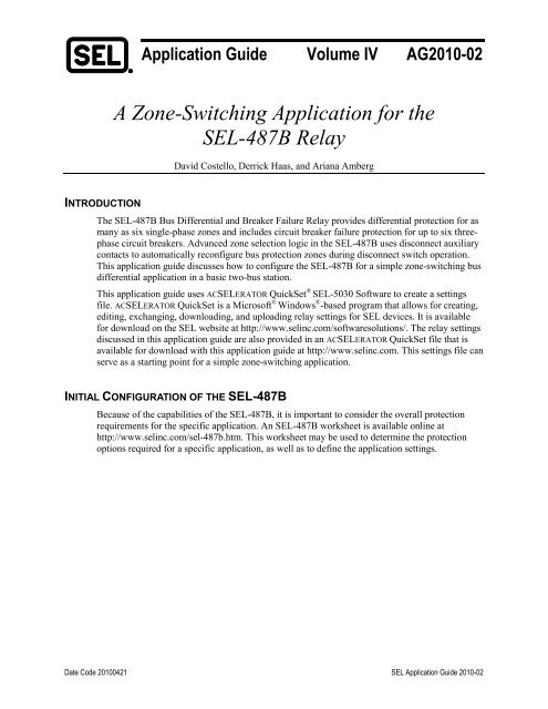
The <strong>SEL</strong>-<strong>487B</strong> Bus Differential and Breaker Failure <strong>Relay</strong> provides differential protection <strong>for</strong> as<br />
many as six single-phase zones and includes circuit breaker failure protection <strong>for</strong> up to six <strong>threephase</strong><br />
circuit breakers. Advanced zone selection logic in <strong>the</strong> <strong>SEL</strong>-<strong>487B</strong> uses disconnect auxiliary<br />
contacts to automatically reconfigure bus protection zones during disconnect switch operation.<br />
This application guide discusses how to configure <strong>the</strong> <strong>SEL</strong>-<strong>487B</strong> <strong>for</strong> a simple zone-switching bus<br />
differential application in a basic two-bus station.<br />
This application guide uses AC<strong>SEL</strong>ERATOR QuickSet ® <strong>SEL</strong>-5030 Software to create a settings<br />
file. AC<strong>SEL</strong>ERATOR QuickSet is a Microsoft ® Windows ® -based program that allows <strong>for</strong> creating,<br />
editing, exchanging, downloading, and uploading relay settings <strong>for</strong> <strong>SEL</strong> devices. It is available<br />
<strong>for</strong> download on <strong>the</strong> <strong>SEL</strong> website at http://www.selinc.com/softwaresolutions/. The relay settings<br />
discussed in this application guide are also provided in an AC<strong>SEL</strong>ERATOR QuickSet file that is<br />
available <strong>for</strong> download with this application guide at http://www.selinc.com. This settings file can<br />
serve as a starting point <strong>for</strong> a simple zone-switching application.<br />
INITIAL CONFIGURATION OF THE <strong>SEL</strong>-<strong>487B</strong><br />
Because of <strong>the</strong> capabilities of <strong>the</strong> <strong>SEL</strong>-<strong>487B</strong>, it is important to consider <strong>the</strong> overall protection<br />
requirements <strong>for</strong> <strong>the</strong> specific application. An <strong>SEL</strong>-<strong>487B</strong> worksheet is available online at<br />
http://www.selinc.com/sel-487b.htm. This worksheet may be used to determine <strong>the</strong> protection<br />
options required <strong>for</strong> a specific application, as well as to define <strong>the</strong> application settings.<br />
Date Code 20100421 <strong>SEL</strong> <strong>Application</strong> Guide 2010-02
2<br />
Table 1 is from <strong>the</strong> <strong>SEL</strong>-<strong>487B</strong> worksheet and lists <strong>the</strong> protection functions that are used in this<br />
application. This example only uses basic bus differential protection.<br />
Table 1 Standard Protection Functions<br />
Protection Function<br />
CT (current trans<strong>for</strong>mer) ratio mismatch smaller than 10:1<br />
Circuit breaker status logic<br />
Disconnect monitor logic<br />
Differential protection<br />
Dynamic zone selection logic<br />
Sensitive differential protection<br />
<strong>Zone</strong> supervision logic<br />
<strong>Zone</strong>-switching supervision logic<br />
Coupler security logic<br />
Circuit breaker failure protection<br />
Instantaneous overcurrent protection<br />
Time-overcurrent protection<br />
Phase voltage elements<br />
Zero- or negative-sequence voltage elements<br />
Selection<br />
Yes<br />
Yes<br />
Yes<br />
Yes<br />
Yes<br />
Yes<br />
No<br />
No<br />
No<br />
No<br />
No<br />
No<br />
No<br />
No<br />
CONFIGURATION OF CURRENT INPUTS<br />
Because busbar protection applications differ substantially from station to station, we show a<br />
basic station application that excludes all protection functions except busbar protection. Figure 1<br />
is a one-line diagram of <strong>the</strong> application. The bus zone includes seven three-phase circuit breakers.<br />
Note that <strong>the</strong> ratios of <strong>the</strong> CTs are not all <strong>the</strong> same.<br />
Figure 1<br />
<strong>Application</strong> One-Line Diagram<br />
<strong>SEL</strong> <strong>Application</strong> Guide 2010-02 Date Code 20100421
3<br />
None of <strong>the</strong> current inputs to <strong>the</strong> <strong>SEL</strong>-<strong>487B</strong> are preassigned, which provides maximum flexibility<br />
in applying <strong>the</strong> relay. The <strong>SEL</strong>-<strong>487B</strong> can accommodate 18 individual current inputs. For this<br />
application, <strong>the</strong> bus differential protection requires all 18 inputs: Phase A, B, and C currents from<br />
each of <strong>the</strong> breakers (<strong>the</strong> phase currents from Breakers 1 and 2 are paralleled and share relay<br />
inputs).<br />
Because of <strong>the</strong> number of current inputs on <strong>the</strong> <strong>SEL</strong>-<strong>487B</strong> and <strong>the</strong> fact that this application has<br />
more than six breakers, CTs from Breakers 1 and 2 are paralleled to one input on <strong>the</strong> <strong>SEL</strong>-<strong>487B</strong>.<br />
Each of <strong>the</strong>se breakers serves a radial load only. Do not parallel source and load CTs to <strong>the</strong> same<br />
inputs of <strong>the</strong> relay, and do not parallel two sources to <strong>the</strong> same input of <strong>the</strong> relay. For external<br />
faults, <strong>the</strong> paralleled connection of a source and load, or two sources, would reduce restraint<br />
current and make <strong>the</strong> relay less secure.<br />
There are three three-phase 161 kV breakers on Bus A: Breakers 1, 2, and 3. There are four<br />
three-phase 161 kV breakers on Bus B: Breakers 5, 6, 7, and 8. A motor-operated switch<br />
(MOS 4) connects Bus A to Bus B.<br />
Faults on Bus A trip Breakers 1, 2, and 3 when MOS 4 is open and Breakers 1, 2, 3, 5, 6, 7, and 8<br />
when MOS 4 is closed. Faults on Bus B trip Breakers 5, 6, 7, and 8 when MOS 4 is open and<br />
Breakers 1, 2, 3, 5, 6, 7, and 8 when MOS 4 is closed.<br />
Table 2 shows <strong>the</strong> external CT connections corresponding to <strong>the</strong> current input assignments in <strong>the</strong><br />
<strong>SEL</strong>-<strong>487B</strong>. The order and grouping of <strong>the</strong> current inputs are flexible. In this example, <strong>the</strong> <strong>threephase</strong><br />
currents from each breaker are grouped on each row. The inputs are also grouped by phase<br />
in each column.<br />
Table 2<br />
<strong>SEL</strong>-<strong>487B</strong> Current Input Assignments<br />
Terminal Phase A Phase B Phase C CT Ratio<br />
1 I01 I02 I03 2000/5Y<br />
2 I01 I02 I03 2000/5Y<br />
3 I04 I05 I06 2000/5Y<br />
5 I07 I08 I09 2000/5Y<br />
6 I10 I11 I12 600/5Y<br />
7 I13 I14 I15 2000/5Y<br />
8 I16 I17 I18 2000/5Y<br />
This application requires six separate bus zones—one per phase on each bus. Table 3 shows <strong>the</strong><br />
bus zone assigned to each current input.<br />
Table 3<br />
<strong>SEL</strong>-<strong>487B</strong> Bus <strong>Zone</strong> Assignments<br />
Bus <strong>Zone</strong> Description Terminals<br />
1 Bus A, Phase A differential I01, I04<br />
2 Bus A, Phase B differential I02, I05<br />
3 Bus A, Phase C differential I03, I06<br />
4 Bus B, Phase A differential I07, I10, I13, I16<br />
5 Bus B, Phase B differential I08, I11, I14, I17<br />
6 Bus B, Phase C differential I09, I12, I15, I18<br />
Date Code 20100421 <strong>SEL</strong> <strong>Application</strong> Guide 2010-02
4<br />
Figure 2 shows how to program <strong>the</strong> terminal-to-bus-zone connections using AC<strong>SEL</strong>ERATOR<br />
QuickSet.<br />
Figure 2 AC<strong>SEL</strong>ERATOR QuickSet Settings to Connect <strong>Relay</strong> Terminal I01 to Bus <strong>Zone</strong> 1<br />
ALIASES<br />
Alias settings can be used in <strong>the</strong> <strong>SEL</strong>-<strong>487B</strong> to rename current and digital inputs to something<br />
significant to <strong>the</strong> user. The alias used is arbitrary and intended to provide easy identification <strong>for</strong><br />
metering, logic, and event reports. In this application guide, aliases are not used in order to allow<br />
<strong>the</strong> user to cross-reference standard <strong>Relay</strong> Word bit names in logic.<br />
ZONE SWITCHING<br />
A disconnect auxiliary contact provides <strong>the</strong> zone selection logic with <strong>the</strong> in<strong>for</strong>mation required to<br />
dynamically assign current inputs to <strong>the</strong> appropriate differential elements. In this example, <strong>the</strong><br />
<strong>SEL</strong>-<strong>487B</strong> is set such that Bus <strong>Zone</strong>s 1 and 4 merge when MOS 4 closes. Bus <strong>Zone</strong>s 2 and 5<br />
merge when MOS 4 closes. Bus <strong>Zone</strong>s 3 and 6 merge when MOS 4 closes. Figure 3 shows <strong>the</strong><br />
settings to connect Bus <strong>Zone</strong> 1 to Bus <strong>Zone</strong> 4.<br />
Figure 3 AC<strong>SEL</strong>ERATOR QuickSet Settings to Connect Bus <strong>Zone</strong> 1 to Bus <strong>Zone</strong> 4<br />
The <strong>SEL</strong>-<strong>487B</strong> includes disconnect switch monitor logic. This logic requires both normally open<br />
(89A) and normally closed (89B) disconnect auxiliary contacts. In this application example, <strong>the</strong><br />
disconnect monitor logic is not used. An 89A contact is not wired to <strong>the</strong> relay; only an 89B<br />
contact is used.<br />
<strong>SEL</strong> <strong>Application</strong> Guide 2010-02 Date Code 20100421
5<br />
The 89B contact is used to initiate <strong>the</strong> merging of bus zones by way of <strong>the</strong> zone selection logic. It<br />
is critical to <strong>the</strong> security of <strong>the</strong> relay that <strong>the</strong> bus zones be merged be<strong>for</strong>e arcing begins as MOS 4<br />
closes and that <strong>the</strong> zones be unmerged after arcing ends as MOS 4 opens. As Figure 4 shows, an<br />
89B contact provides this functionality. Do not attempt to use an 89A contact alone <strong>for</strong> initiating<br />
zone selection logic, as relay security will be compromised during MOS arcing.<br />
Figure 4<br />
Motor-Operated Disconnect Switch Operation<br />
DIFFERENTIAL PROTECTION<br />
Because <strong>the</strong> relay accepts current inputs from CTs with a 10:1 ratio mismatch, <strong>the</strong> calculations <strong>for</strong><br />
<strong>the</strong> differential elements are per<strong>for</strong>med on per-unit values. The relay uses <strong>the</strong> highest CT ratio<br />
(CTR MAX ) of <strong>the</strong> installed CT ratios as a reference value in converting <strong>the</strong> input currents from<br />
amperes to per-unit values.<br />
CTR<br />
MAX<br />
• INOM<br />
TAPnn = (1)<br />
CTRnn<br />
where:<br />
TAPnn = TAP value <strong>for</strong> each terminal to convert current from amperes to per unit<br />
(nn = 01 through 18).<br />
CTR MAX = highest CT ratio of <strong>the</strong> terminals used in <strong>the</strong> terminal-to-bus-zone settings.<br />
I NOM = nominal CT secondary current (1 or 5 amperes).<br />
CTRnn = CT ratio of <strong>the</strong> specific terminal.<br />
Using <strong>the</strong> TAPnn values, <strong>the</strong> relay calculates <strong>the</strong> current in per-unit values <strong>for</strong> each terminal as<br />
follows:<br />
Inn<br />
InnCR = pu<br />
(2)<br />
TAPnn<br />
where:<br />
InnCR = per-unit current <strong>for</strong> Terminals I01 through I18.<br />
Inn = current in amperes <strong>for</strong> Terminals I01 through I18.<br />
pu = per unit.<br />
The minimum sensitivity of <strong>the</strong> differential element is defined by <strong>the</strong> setting O87P and <strong>the</strong> CT<br />
ratios. For this application, assume <strong>the</strong> O87P setting is 0.82 per unit.<br />
Date Code 20100421 <strong>SEL</strong> <strong>Application</strong> Guide 2010-02
6<br />
Using (1) and (2), we can derive a simple expression <strong>for</strong> <strong>the</strong> minimum sensitivity in primary<br />
amperes. See (3). For this application, an O87P setting of 0.82 per unit translates to a minimum<br />
sensitivity of 1640 primary amperes, based on TAP and CT ratio.<br />
Minimum sensitivity (in primary amperes) = O87P • TAPnn • CTRnn (3)<br />
Set O87P low enough to ensure operation of <strong>the</strong> differential element <strong>for</strong> an internal bus fault<br />
when fed from <strong>the</strong> weakest source. Simulate a bus fault under minimum source conditions, and<br />
ensure that <strong>the</strong> minimum sensitivity is below <strong>the</strong> minimum fault current, including margin.<br />
Based on <strong>the</strong> <strong>SEL</strong>OGIC ® control equations IqqBZpV (Terminal-qq-to-Bus-<strong>Zone</strong>-p connections)<br />
and BZpBZrV (Bus-<strong>Zone</strong>-p-to-Bus-<strong>Zone</strong>-r connections), <strong>the</strong> <strong>SEL</strong>-<strong>487B</strong> determines <strong>the</strong><br />
following:<br />
• Bus zone(s) to be included in each protection zone.<br />
• Active terminals to be included in <strong>the</strong> associated protection zone.<br />
• Terminals to trip <strong>for</strong> differential and breaker failure protection operations.<br />
• Differential elements to run.<br />
After <strong>the</strong> relay detects a switching operation (e.g., status change in ZNpIqq), it asserts <strong>the</strong><br />
corresponding zone-switching operation bit, ZSWOPp. Figure 5 shows <strong>the</strong> processing sequence<br />
that <strong>the</strong> relay follows to determine whe<strong>the</strong>r to run <strong>the</strong> differential element. Placeholders p and r<br />
refer to Bus <strong>Zone</strong>s 1 through 6, and qq refers to Terminals 01 through 18. See Figure 5 and<br />
Figure 6.<br />
Figure 5<br />
Flow Logic Diagram <strong>for</strong> Determining Terminals <strong>for</strong> Each <strong>Zone</strong><br />
<strong>SEL</strong> <strong>Application</strong> Guide 2010-02 Date Code 20100421
7<br />
Start<br />
No<br />
87Zn<br />
asserted?<br />
Yes<br />
Read terminals to trip within<br />
<strong>Zone</strong> n from ZNpIqqT<br />
Generate trip <strong>for</strong> <strong>the</strong><br />
selected terminals 87BTRkk<br />
kk = 01...18<br />
End<br />
Figure 6 Flow Logic Diagram <strong>for</strong> Generating Trip Outputs 87BTRkk (kk = Terminals 01 Through 18)<br />
The sensitive differential element 87STn (n = 1 through 6) detects CT open- or short-circuit<br />
conditions. The factory default setting <strong>for</strong> sensitive differential elements is 10 percent of zone<br />
differential element pickup values. This setting of 10 percent allows sensitive differential<br />
elements to respond to CT problems, even under low-load conditions. With sensitive differential<br />
element supervision enabled (E87SSUP = Y), <strong>the</strong> time-delayed outputs of <strong>the</strong> sensitive<br />
differential elements (87STn) block <strong>the</strong> zone differential elements (87Rn) from operating.<br />
For this application, we route <strong>the</strong> time-delayed output of <strong>the</strong> sensitive differential element to<br />
output OUT201. Connect OUT201 to SCADA (supervisory control and data acquisition) <strong>for</strong><br />
remote indication. If blocking <strong>the</strong> zone differential elements is not desired, set E87SSUP = N.<br />
Note that <strong>the</strong> operation of <strong>the</strong> sensitive differential element (87STn) is independent of <strong>the</strong><br />
E87SSUP setting. Thus, OUT201 still asserts <strong>for</strong> CT problems when E87SSUP = N.<br />
Date Code 20100421 <strong>SEL</strong> <strong>Application</strong> Guide 2010-02
8<br />
TRIP OUTPUT LOGIC<br />
Figure 7 identifies trip logic needed <strong>for</strong> this application. Each <strong>SEL</strong>-<strong>487B</strong> terminal has a trip <strong>Relay</strong><br />
Word bit, 87BTRkk. Because this is a three-pole trip application, we can combine <strong>the</strong> Phase A, B,<br />
and C trips into one output <strong>for</strong> each breaker. In this example, TR01 represents <strong>the</strong> trip logic <strong>for</strong><br />
Breaker 1.<br />
Figure 7<br />
<strong>SEL</strong>-<strong>487B</strong> Trip Logic<br />
<strong>SEL</strong> <strong>Application</strong> Guide 2010-02 Date Code 20100421
9<br />
Figure 8 shows <strong>the</strong> output contact programming <strong>for</strong> this application. OUT101, <strong>for</strong> example, is <strong>the</strong><br />
trip output contact <strong>for</strong> Breaker 1 and is set equal to TRIP01. TRIP01 asserts when TR01 is a<br />
logical 1, which occurs <strong>for</strong> Phase A, B, or C trips to Breaker 1. These trips are <strong>the</strong> result of <strong>the</strong><br />
87BTRkk <strong>Relay</strong> Word bits, which in turn are <strong>the</strong> result of <strong>the</strong> terminal and bus zone logic and<br />
differential elements.<br />
Figure 8<br />
<strong>SEL</strong>-<strong>487B</strong> Output Logic<br />
REPORT SETTINGS<br />
The report settings do not affect <strong>the</strong> differential protection, but <strong>the</strong>y do provide valuable<br />
in<strong>for</strong>mation <strong>for</strong> evaluating relay operations. The <strong>SEL</strong>-<strong>487B</strong> includes both SER (Sequential Events<br />
Recorder) and event report (oscillography) files. Note that <strong>the</strong> default SER settings do not include<br />
any points. For this example, only relevant <strong>Relay</strong> Word bits <strong>for</strong> this application were included in<br />
<strong>the</strong> SER settings and <strong>the</strong> list of digital elements <strong>for</strong> event reports.<br />
CONCLUSION<br />
This application guide provides an introduction to setting <strong>the</strong> <strong>SEL</strong>-<strong>487B</strong> <strong>for</strong> a simple bus zoneswitching<br />
differential application. The settings developed in this guide may be used as a starting<br />
point to create settings <strong>for</strong> a specific bus differential application.<br />
Date Code 20100421 <strong>SEL</strong> <strong>Application</strong> Guide 2010-02
10<br />
FACTORY ASSISTANCE<br />
We appreciate your interest in <strong>SEL</strong> products and services. If you have questions or comments,<br />
please contact us at:<br />
Schweitzer Engineering Laboratories, Inc.<br />
2350 NE Hopkins Court<br />
Pullman, WA 99163-5603 USA<br />
Telephone: +1.509.332.1890<br />
Fax: +1.509.332.7990<br />
www.selinc.com • info@selinc.com<br />
© 2010 by Schweitzer Engineering Laboratories, Inc.<br />
All rights reserved.<br />
All brand or product names appearing in this document are<br />
<strong>the</strong> trademark or registered trademark of <strong>the</strong>ir respective<br />
holders. No <strong>SEL</strong> trademarks may be used without written<br />
permission.<br />
<strong>SEL</strong> products appearing in this document may be covered by<br />
U.S. and Foreign patents.<br />
*AG2010-02*<br />
<strong>SEL</strong> <strong>Application</strong> Guide 2010-02 Date Code 20100421