PDS-ABS/OV
PDS-ABS/OV - CP Electronics
PDS-ABS/OV - CP Electronics

You also want an ePaper? Increase the reach of your titles
YUMPU automatically turns print PDFs into web optimized ePapers that Google loves.
<strong>PDS</strong>-<strong>ABS</strong>/<strong>OV</strong><br />
No Neutral Absence Detector<br />
Product Guide<br />
Overview<br />
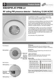
The <strong>PDS</strong>-<strong>ABS</strong>/<strong>OV</strong> absence detector switch replaces a standard single gang light<br />
switch. A press switch on the front of the unit allows the lights (either incandescent<br />
or fluorescent) to be turned on and off like a normal light switch.<br />
An integral occupancy detector ensures that if the area is vacated, then the lights<br />
are automatically turned off at the end of the adjustable time out period.<br />
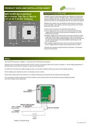
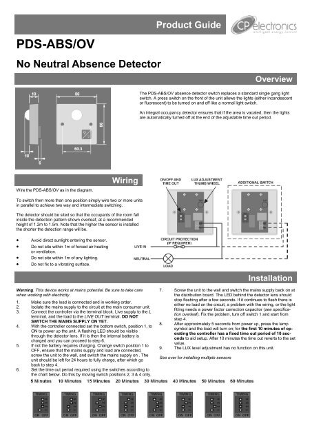
Wire the <strong>PDS</strong>-<strong>ABS</strong>/<strong>OV</strong> as in the diagram.<br />
Wiring<br />
To switch from more than one position simply wire two or more units<br />
in parallel to achieve two way and intermediate switching.<br />
The detector should be sited so that the occupants of the room fall<br />
inside the detection pattern shown overleaf, at a recommended<br />
height of 1.2m to 1.5m. Note that the higher the sensor is installed<br />
the shorter the detection range will be.<br />
<br />
<br />
<br />
<br />
Avoid direct sunlight entering the sensor.<br />
Do not site within 1m of forced air heating<br />
or ventilation.<br />
Do not site within 1m of any lighting.<br />
Do not fix to a vibrating surface.<br />
Installation<br />
Warning. This device works at mains potential. Be sure to take care<br />
when working with electricity.<br />
1. Make sure the load is connected and in working order.<br />
2. Isolate the mains supply to the circuit at the main consumer unit.<br />
3. Connect the controller via the terminal block. Live supply to the L<br />
terminal, and the load to the LIVE OUT terminal. DO NOT<br />
SWITCH THE MAINS SUPPLY ON YET.<br />
4. With the controller connected set the bottom switch, position 1, to<br />
ON to power up the unit. A flashing LED should be visible<br />
through the detector lens. If it is then the internal battery is<br />
charged and you can proceed to step 6.<br />
5. If not the battery requires charging. Change switch position 1 to<br />
OFF, ensure that the mains supply and load are connected,<br />
screw the unit to the wall, and switch the mains supply on . The<br />
unit should be left for 24 hours to fully charge, after which go<br />
back to step 4.<br />
6. Set the time out period required using the switches according to<br />
the chart below. Do this by moving switch positions 2, 3 & 4 only.<br />
7. Screw the unit to the wall and switch the mains supply back on at<br />
the distribution board. The LED behind the detector lens should<br />
stop flashing after a few seconds. If it continues to flash there is<br />
either no load on the circuit, a problem with the wiring, or the light<br />
fitting needs a power factor correction capacitor (see specification<br />
overleaf). Fix the problem, turn off switch 1 and start from<br />
step 4.<br />
8. After approximately 5 seconds from power up, press the lamp<br />
symbol and the load will turn on; for the first 10 minutes of operating<br />
the controller has a fixed time out period of 10 seconds<br />
to aid setup. After 10 minutes the time out reverts to the set<br />
value.<br />
9. The LUX level adjustment has no function on this unit.<br />
See over for installing multiple sensors
Installation cont.<br />
Installing multiple sensors<br />
1. When using multiple <strong>PDS</strong>-<strong>ABS</strong>/<strong>OV</strong> sensors to control the same load it is important that each sensor is turned off before the next sensor is<br />
installed.<br />
2. When the each sensor has been installed and is working, simply press the lamp symbol to turn the lights off.<br />
3. After installation has finished, press the lamp symbol on each sensor again to turn the lights back on.<br />
Detection Pattern<br />
Fault Finding<br />
LIGHTS DO NOT COME ON<br />
Press the lamp symbol .<br />
Check to see if the live supply to the circuit is<br />
good. Strap across the L and LIVE OUT terminal<br />
to turn the load on.<br />
If the load still fails to turn on follow step 5 of<br />
the installation instructions to recharge the internal<br />
battery.<br />
LIGHTS DO NOT GO OFF<br />
Ensure that the area is left unoccupied for a<br />
greater time period than the time out period set<br />
using the switch.<br />
Make sure that the sensor is not adjacent to<br />
circulating air, heaters or lamps.<br />
LIGHTS FLICKER<br />
Ensure that there are sufficient power factor<br />
correction capacitors fitted.<br />
Specification<br />
LOAD<br />
10 Amp incandescent lighting<br />
6 Amp fluorescent lighting<br />
3 Amp compact fluorescent lighting<br />
3 Amp low energy lighting<br />
3 Amp low voltage lighting (switch primary of transformer)<br />
Fluorescent lighting (max 6 fittings recommended)<br />
Fluorescent and compact fluorescent fittings with “switch start” ballasts - 6 ballasts maximum.<br />
Power factor correction capacitors must be fitted.<br />
Most fluorescent fittings have power factor correction capacitors fitted. If they are not present<br />
the unit may fail the installation procedure, in which case fit one capacitor per circuit with a<br />
minimum value of 1μF for every <strong>PDS</strong> or <strong>PDS</strong>-<strong>OV</strong> installed. Note that it is not necessary to fit a<br />
capacitor on every fitting.<br />
For fluorescent lighting total power factor correction capacitance must not exceed 40μF.<br />
Not suitable for switching contactors<br />
Not suitable for SON lighting<br />
Not suitable for heating or ventilation loads.<br />
Please contact our sales department for a suitable alternative product.<br />
SUPPLY VOLTAGE<br />
TIME OUT PERIOD<br />
LIGHT LEVEL<br />
FIXING METHOD<br />
TERMINAL CAPACITY 1.5mm 2<br />
MATERIAL<br />
Flame retardant <strong>ABS</strong><br />
TYPE Class 2<br />
TEMPERATURE -10°C to 35°C<br />
CONFORMITY EMC-89/336/EEC<br />
LVD-73/23/EEC<br />
220-240 Volts AC 50 Hz<br />
Adjustable 5 minutes to 60 minutes by DIP switch.<br />
Adjustable by thumbwheel light to dark.<br />
Surface fixing 25mm deep plastic surface mount moulded box.<br />
Flush fixing 15mm steel wall box or 32mm deep cavity wall box.<br />
IMPORTANT NOTICE!<br />
This device should be installed by a<br />
qualified electrician in accordance with<br />
the latest edition of the IEE wiring<br />
regulations.<br />
FM 45789 EMS 534520<br />
Due to our policy of continual product improvement CP Electronics reserves the right to alter the specification of this product without prior notice.<br />
C.P. Electronics Ltd<br />
Brent Crescent<br />
London<br />
NW10 7XR<br />
United Kingdom<br />
Tel: + 44 (0) 333 900 0671<br />
Fax: + 44 (0) 333 900 0674<br />
www.cpelectronics.co.uk<br />
enquiry@cpelectronics.co.uk<br />
Ref #WD143 Issue 4