

DID TEURS
MagaZine - Free and Open Source Software
MagaZine - Free and Open Source Software
- No tags were found...

You also want an ePaper? Increase the reach of your titles
YUMPU automatically turns print PDFs into web optimized ePapers that Google loves.
SA T1 ( A.<br />
51(&1<br />
':Ji<br />
•<br />
. "<br />
k ..<br />
•<br />
•<br />
'"<br />
I<br />
02 I~ T1<br />
., ..<br />
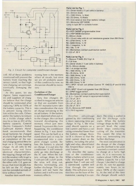
Fig. 3. Circuit fo r complete conditioner/c harger.<br />
cell. Al l of the se problems<br />
mentioned will p revent t he<br />
battery from reaching the<br />
se nsor cutoff, so that highrate<br />
charg ing can continue,<br />
eventually damaging the<br />
battery.<br />
At t hi s point. let m e<br />
d igress. Som e experimenters<br />
and suppliers of chargers<br />
believe that the cha rge<br />
sho uld be term inated aft er<br />
replacing 130% t01 50% of<br />
the battery ca pacity. This is<br />
to prevent lo sing elect rolyte<br />
within the cells. O thers<br />
prefer the battery to remain<br />
on a trickl e charge wh ich<br />
may be as low as .01C of the<br />
battery capac ity. Ce ne ra l<br />
Electric Co m pany's Nickel<br />
Cadm ium Battery Handbook<br />
recommends that<br />
nicad batteries be c ha rged<br />
at a fairly high rate, but that<br />
at completion of the normal<br />
c ha rging period they be<br />
kept on a .j Ccra te topping<br />
cha rge . As all cells in the<br />
battery may no t h a ve<br />
identical c haracteris tics,<br />
the topping c ha rge will perm<br />
it the weaker cells to get a<br />
fu ll charge without harming<br />
the othe r cells . C .E . goes on<br />
to say that mo st nlcads may<br />
be left on the .1C cha rge<br />
rate for extended periods of<br />
time without harm.<br />
Another item worth men-<br />
" ,---+-,<br />
..<br />
@<br />
@ ..<br />
"<br />
_ 5T & ~ T<br />
•<br />
pu ..SE<br />
'"<br />
"" ,<br />
I<br />
I<br />
, I<br />
-v<br />
I<br />
'x'<br />
•<br />
"'<br />
.,<br />
An other adva n tage<br />
ga ined by this cond itioning<br />
is more o perati ng time per<br />
charge. In Fig. 1, the re lay<br />
used should operat e on a<br />
low current and ha ve a coi l<br />
rating somewha t lower than<br />
the batte ry voltage. Re sistor<br />
R is chosen so that the<br />
total current dra in on the<br />
battery, includ ing the pilot<br />
light and rel ay, sho uld total<br />
the Ampere-ho ur rating of<br />
your battery.<br />
To describe t he operation<br />
o f the condit ioner:<br />
When a battery whi ch is no t<br />
fully discharged and has<br />
greater tha n 1 volt per cel l<br />
is connected, current will<br />
flow through t he ze ner<br />
diode. This will place a positive<br />
bias on t he base of the<br />
transistor, causing it to canc<br />
r<br />
.'2" " " UI<br />
•<br />
" DOu c E ]I<br />
" ..,<br />
T e ,<br />
boning here is the memory<br />
effect o f nicads, but since<br />
we are all probably aware<br />
o f this cond itio n by now, no<br />
disc ussion should be necessary.<br />
Evolution of the<br />
Condi tioner/Charger<br />
Ve ry few chargers described<br />
in magazine articles<br />
o r that are available from<br />
the HT manufacturers take<br />
into considerat ion the state<br />
of charge remaining in the<br />
nicad battery. If the battery<br />
is no t depleted when put into<br />
t he charger, this can lead<br />
towa rd d e ve lopin g t he<br />
memory effect just mentioned.<br />
To prevent thi s from<br />
happening, the cond itioner<br />
shown in Fig. 1 was developed.<br />
This can be built as a<br />
stand-alone unit or may be<br />
inc orpora ted into a complete<br />
charger system. Before<br />
the battery is pl aced<br />
on cha rge, it is put into the<br />
conditioner. It will immediately<br />
go into disc harge at<br />
the 1C rate. When the battery<br />
voltage d ro ps to the<br />
t-volt-per-cel l cutoff point<br />
the relay will drop o ut,<br />
thereby termina ting a ny<br />
fu rt her d ischarge . This procedure<br />
will no t harm the<br />
battery and it will erase any<br />
memory effects.<br />
Parts list lor Fig. 1<br />
0 1- Zener diode (1 V per cells in battery)<br />
02-Silicon diode<br />
Rl-1ooo Ohms, % Wall<br />
R2-75 Ohms, 10 Walls<br />
AY-Coil rated at less than battery voltage<br />
01-Motorola HEP 50038<br />
Lamp is type 387 in sui table holder.<br />
Parts List IOf Fig. 2<br />
IC-HEP C4058P programmable timer<br />
Q'-HEP SOO38 transistor<br />
D-Sllicon diode<br />
RY-12·volt relay with dc coil resistance greater than 250 Ohm s<br />
R1-27oo Ohms, V. W<br />
R2-6200 Ohms, V. W<br />
R3-1 megohm, V. W<br />
R4-10k, 'I. W<br />
S1-Momentary contact push-button switch<br />
C-2.2 uF, 35 V<br />
Parts List lor Fig. 3<br />
T- Stancor P 6469, 25.2 ve t A<br />
F-1-A fuse<br />
nt-c-zener diode (1 V per celts in battery)<br />
02, 3-Sillcon diodes<br />
D4-1-A bridge rectifier<br />
R1-1ooo Ohms, '12 W<br />
R2-75 Ohms, 10 W<br />
R3-1ooo Ohms, V~ W<br />
R4-25O Ohms, 10 W<br />
R5-430 Ohms, '!J W<br />
R6-620 Ohms, V~ W<br />
RY1 - 4POT tz-vou coil (Allied Control TF 154C-C) (P and B KHU<br />
1701 1)<br />
AY2-SPST 12-..,011 coil (greater than 250 OhmS)<br />
S1 - OPST toggle switch<br />
S2-Momentary contact push-button-type switch<br />
L1 , 2. 3-Type 387 lamps in appropriate holders<br />
Cl - 10 uF, 25 V<br />
C2-4_7 uF, 35 V<br />
C3 - .47 uF, 35 V<br />
C4-50 uF, 50 V<br />
01 , 2- Motorola HEP SOO38<br />
IC1- 7812 regulator<br />
duct. The relay is pulled in<br />
and the discharge cycle<br />
starts . When the battery<br />
vo ltage drops to the t -voltper-eel!<br />
level, the zener<br />
diode sto ps co nd uc ting,<br />
cutting o ff the transistor.<br />
This causes the re lay to<br />
d rop o ut. terminating a ny<br />
fur ther di sch arge .<br />
The next considera tion in<br />
the design of the charger<br />
was the method to be used.<br />
I wanted a constant current<br />
to cha rge at a fai rly high<br />
rate . As it is necessary to<br />
replace about 130 % of the<br />
battery capacity for a full<br />
charge, I decided to cha rge<br />
at the .sC rate for approx i<br />
mately two ho urs to rep<br />
lace 100% o f the capacity.<br />
At the end of this time<br />
the charge r sho uld switc h<br />
73 Magazine· Aprll ,1981 107


