

DID TEURS
MagaZine - Free and Open Source Software
MagaZine - Free and Open Source Software
- No tags were found...

You also want an ePaper? Increase the reach of your titles
YUMPU automatically turns print PDFs into web optimized ePapers that Google loves.
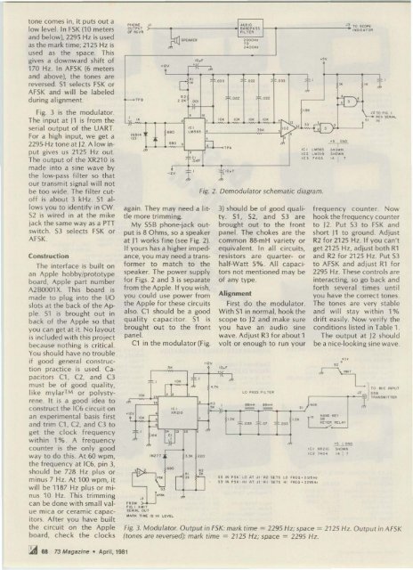
tone comes in, it puts out a<br />
low level. In F5K (10 meters<br />
and below), 2295 Hz is used<br />
as the mark time; 2125 Hz is<br />
used as the space. This<br />
gives a downward shift of<br />
170 Hz . In AF5K (6 meters<br />
and above), the tones are<br />
reversed. 51 selects F5K or<br />
AF 5K and will be labeled<br />
during al ignment.<br />
Fig. 3 is the modulator.<br />
The input at J1 is from the<br />
serial output of the UART.<br />
For a high input, we get a<br />
2 295~Hz toneat J2. A low input<br />
gives us 2125 Hz out.<br />
The output of the XR210 is<br />
made into a sine wave by<br />
the low-pass filter so that<br />
our transmit signal will not<br />
be too wide. The filter cutoff<br />
is about 3 kHz. 51 a l<br />
lows you to ide ntify in CWo<br />
52 is wired in at the mike<br />
jack the sa me way as a PTT<br />
switc h. 53 selec ts F5K or<br />
AF SK .<br />
Conslruction<br />
The interface is built on<br />
a n Apple hobby/prototype<br />
board, Apple part number<br />
A2BOOO1X. This board is<br />
made to plug into the Ifa<br />
slots at the back of the Apple.<br />
51 is brought out in<br />
back of the Apple so that<br />
you can get at it. No layout<br />
is included with this projec t<br />
because nothing is critical.<br />
You sho uld have no trouble<br />
if good general construct<br />
ion practice is used. Capacitors<br />
C1 , C2, and C3<br />
mu st be of good quality,<br />
like mvlart or polystyrene<br />
. It is a good idea to<br />
construct the IC6 circuit on<br />
a n e xperime ntal basis first<br />
and trim C1, C2, and C3 to<br />
get the clock frequency<br />
within 1 % . A frequency<br />
counte r is the only good<br />
way to do this. At 60 wpm,<br />
the frequency at IC6, pin 3,<br />
should be 728 Hz plus or<br />
minus 7 Hz. At 100 wpm, it<br />
will be 1187 Hz plus o r m i<br />
nus 10 Hz. This tr imming<br />
ca n be done with small value<br />
mica o r ceramic capacitors.<br />
After yo u have built<br />
the ci rcuit on the Apple<br />
board, c heck the clocks<br />
'" "<br />
· I2 V<br />
_12v<br />
'0_'<br />
"<br />
, ," l'<br />
Fig. 2. Demodulator schematic diagram.<br />
3) should be of good quality.<br />
51 , 52, and 53 are<br />
brought out to the front<br />
panel. The c hokes a re the<br />
common 88-mH variety or<br />
equivalent. In all circuits,<br />
resisto rs are quarter- or<br />
half-Watt 5%. All capacitors<br />
not mentioned may be<br />
of a ny type.<br />
Alignment<br />
First do the modula to r.<br />
W it h 51 in normal , hook the<br />
scope to 12 a nd make su re<br />
you ha ve a n a udio sine<br />
wave. Adjust R3 fo r a bout 1<br />
volt or enough to run you r<br />
. ~<br />
I.<br />
'"<br />
• , LO HS$ FlLT(A<br />
_. _. m 00 • ., , ."<br />
'" • -<br />
" f,,,<br />
"<br />
frequency counter. Now<br />
hook the frequency counter<br />
to 12. Put 53 to F5K and<br />
sho rt J1 to ground. Adjust<br />
R2 for 2125 Hz. If you can't<br />
get 2125 Hz, adjust both R1<br />
and R2 for 2125 Hz . Put 53<br />
to AF5K and adjust R1 for<br />
2295 Hz. These co ntro ls are<br />
interacting, so go back and<br />
fo rth several times until<br />
you have the correct tones.<br />
The tones a re very stable<br />
and will stay within 1 %<br />
d rift easily. Now verify the<br />
conditions listed in Table 1.<br />
The output at J2 should<br />
be a nice-loo king sine wave.<br />
L TO oo,e '''PUT<br />
"!) m<br />
TU"SWIHU<br />
Fig. 3. Modulator. Output in FSK: mark time = 2295 Hz; space = 2125 Hz. Output in A FSK<br />
(tones a re re versed): mark time = 2125 Hz; space = 2295 Hz.<br />
• ".<br />
J \ .....<br />
U 210<br />
. ~ v<br />
~ r-'<br />
r<br />
....0Cl >lH<br />
• ~<br />
," ".<br />
.05' " H f " ""L"Y<br />
• /<br />
00<br />
l '<br />
''2' •<br />
•• "<br />
' ''217<br />
" " •<br />
- ", "<br />
7,<br />
"<br />
"<br />
PHO ~f<br />
. uOIO<br />
OUTPur<br />
UOIOH S S<br />
01 IlCY ~ ',LHA<br />
'ROoo<br />
r iG I " 'H<br />
URI." OU T<br />
...<br />
$PU >I ( A 2000H,<br />
rc<br />
2 400'"<br />
..'<br />
';V<br />
.(<br />
_ TP .<br />
.,<br />
[<br />
y~ ., I ""0<br />
,.. no<br />
.~<br />
..<br />
- " .!:<br />
H ,.. Fs" · LO U J" 112 SETS LO '''f O ' 212S H.<br />
n ,.. ~ s ~<br />
"'<br />
AT J'<br />
'"<br />
"'<br />
SETS '" ' ''[0 • n9SH.<br />
.,.<br />
U2'0 S.. OW ..<br />
lct 140_ 00 ' •<br />
H TO SCOPt:<br />
' ~OICUO~<br />
'"<br />
",. m ,u<br />
.. ..<br />
'"<br />
r ±<br />
'" '" ~ , J..<br />
'" -If.' ...<br />
l:"<br />
,<br />
00 ~<br />
• • '" '" '" • I" '"<br />
'",<br />
UO S . S • •<br />
.. •<br />
.<br />
.,.<br />
."C -J , .<br />
'C2 ,.<br />
'" ".<br />
" ,<br />
." .,<br />
• ... ,<br />
L OO"$ 5.. 0 ..... '"<br />
• ,<br />
'" L OO 3' 9 s..o.....<br />
cr<br />
'" HO l 00<br />
.04'<br />
'" I •<br />
'" ;,<br />
•<br />
I ~" 4 •<br />
• , ~'O •<br />
again. They may need a littIe<br />
more trimming.<br />
My 55B phone-jack output<br />
is 8 Ohms, so a speaker<br />
at 11 works fine (see Fig. 2).<br />
If yours has a higher impedance,<br />
you ma y need a transformer<br />
to ma tc h to the<br />
speaker. The power supply<br />
fo r Figs. 2 and 3 is separate<br />
from the Apple. If you wish,<br />
you could use power from<br />
the Apple for these circuits<br />
also. C1 shou ld be a good<br />
quali ty capacitor. 51 is<br />
brought out to the front<br />
panel.<br />
C1 in the modulator (Fig.<br />
lOU. r ,ooE '$ '" UVEL<br />
.:.:d 68 73 Magazine . April, 1981


