TR1104 - Billy Goat
TR1104 - Billy Goat
TR1104 - Billy Goat
- No tags were found...

Create successful ePaper yourself
Turn your PDF publications into a flip-book with our unique Google optimized e-Paper software.
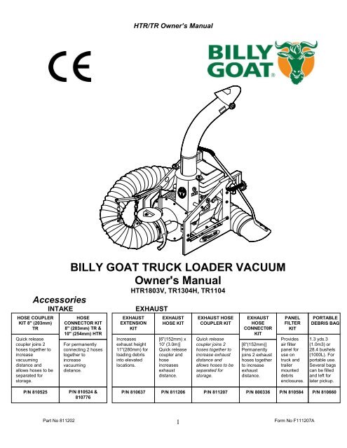
HTR/TR Owner’s Manual<br />
ABOUT THIS MANUAL<br />
THANK YOU for purchasing a BILLY GOAT ® TR/HTR Vacuum. Your new machine has been carefully designed<br />
and manufactured to provide years of reliable and productive service. This manual provides complete operating and<br />
maintenance instructions that will help to maintain your machine in top running order. Read this manual carefully<br />
before assembling, operating, or servicing your equipment.<br />
CONTENTS<br />
SERIAL PLATE DATA AND SPECIFICATIONS 3<br />
GENERAL SAFETY 4 -5<br />
SOUND AND VIBRATION 6<br />
INSTRUCTION LABELS 7<br />
PACKING CHECKLIST & ASSEMBLY 8-9<br />
OPERATION 9-10<br />
MAINTENANCE 11<br />
TROUBLESHOOTING AND WARRANTY PROCEDURE 12<br />
MAINTENANCE RECORD 13<br />
ILLUSTRATED PARTS & PARTS LISTS 14-16<br />
Part No 811202<br />
2<br />
Form No F111207A
HTR/TR Owner’s Manual<br />
SERIAL PLATE DATA<br />
Record the model number, serial number, date of<br />
purchase, and where purchased.<br />
Purchase Date:<br />
Purchased From:<br />
Specifications<br />
HTR1803V TR1304H <strong>TR1104</strong><br />
Engine: HP 18 (13.4 kW) 12 (10.68 kW) 11 (9.04 kW)<br />
Engine: Model 3564420186EI GX390U1QA2 2104320125E1<br />
Engine: Type BRIGGS & STRATTON HONDA BRIGGS & STRATTON<br />
Engine: Fuel Capacity 9qt. (8.52 L) 6.9 qt. (6.0 L) 4.0 qt (3.8 L)<br />
Engine: Oil Capacity 1.75 qt. (1.66 L) 1.16 qt. (1.1 L) 0.875 qt. (0.8 L)<br />
Total Unit Weight: 274# (124.3 kg) 240# (108.0 kg) 224# (101.6 kg)<br />
Max operating slope 20 0 20 0 20 0<br />
Sound in accordance with<br />
2000/14/EEC standards<br />
121 dB(a) 121 dB(a) 121 dB(a)<br />
Sound at operators ear 105 dB(a) 105 dB(a) 105 dB(a)<br />
Vibration at operator position 0.02g 0.02g 0.02g<br />
Part No 811202<br />
3<br />
Form No F111207A
HTR/TR Owner’s Manual<br />
GENERAL SAFETY INSTRUCTIONS and SYMBOLS<br />
The safety symbols shown below are used throughout this manual. You should become familiar with them before<br />
assembling, operating, or servicing this equipment.<br />
This symbol indicates important information that will prevent injury to yourself or others.<br />
This symbol indicates ear protection is recommended when operating this equipment.<br />
This symbol indicates eye protection is recommended when operating this equipment.<br />
This symbol indicates gloves should be worn when servicing this equipment.<br />
This symbol indicates that this manual and the engine manufacturer’s manual should be read<br />
carefully before assembling, operation, or servicing this equipment.<br />
This symbol indicates important information that will prevent damage to your BILLY GOAT ®<br />
HTR/TR VACUUM.<br />
This symbol indicates the engine oil level should be checked before operating this<br />
equipment.<br />
Read and make sure you thoroughly understand the following safety precautions before assembling, operating or<br />
servicing this equipment:<br />
READ this manual and the engine manufacturer’s manual carefully before assembling,<br />
operating, or servicing this equipment.<br />
EAR PROTECTION is recommended when operating this equipment.<br />
EYE PROTECTION is recommended when operating this equipment.<br />
BREATHING PROTECTION is recommended when operating this equipment.<br />
EXHAUST from this product contains chemicals known to the State of California to cause<br />
cancer, birth defects or other reproductive harm.<br />
DO NOT operate this equipment on any unimproved forested, brushy, or grass covered land<br />
unless a spark arrester is installed on the muffler as required by Section 4442 of the<br />
California Public Resources Code. The arrester must be maintained in good working order.<br />
Other states may have similar laws. Federal laws apply on federal lands.<br />
DO NOT run engine in an enclosed area. Exhaust gases contain carbon monoxide, an<br />
odorless and possibly fatal poison.<br />
Part No 811202<br />
4<br />
Form No F111207A
HTR/TR Owner’s Manual<br />
DO NOT run this equipment indoors or in any poorly ventilated area. Refueling outdoors is recommended.<br />
DO NOT refuel this equipment while the engine is running. Allow engine to cool for at least two minutes before<br />
refueling.<br />
DO NOT store gasoline near an open flame.<br />
DO NOT remove gas cap while engine is running.<br />
DO NOT start or operate engine if strong odor of gasoline is present.<br />
DO NOT start or operate engine if gasoline is spilled. Move equipment away from spill until gasoline has<br />
completely evaporated.<br />
DO NOT smoke while filling the fuel tank.<br />
DO NOT check for spark with spark plug or spark plug wire removed. Use an approved spark tester.<br />
DO NOT operate engine without a muffler. Inspect muffler periodically and replace if necessary. If equipped with<br />
muffler deflector, inspect deflector periodically and replace if necessary.<br />
DO NOT operate engine with grass, leaves or other combustible material near the muffler.<br />
DO NOT touch muffler, cylinder, or cooling fins when hot. Contact with hot surfaces may cause severe burns.<br />
DO NOT leave equipment unattended while in operation.<br />
DO NOT operate equipment with bystanders in or near the work area.<br />
DO NOT allow children to operate this equipment.<br />
DO NOT operate equipment with guards removed.<br />
DO NOT operate equipment near or pick up hot or burning debris or any toxic or explosive materials.<br />
DO NOT operate equipment on slopes greater than specified in Specifications section of this manual.<br />
DO NOT start engine without height adjust lever in up position and clutch bail disengaged.<br />
DO NOT place hands or feet inside nozzle intake, near debris outlet, or near any moving parts.<br />
WARNING: Important<br />
DO NOT use this machine for vacuuming exclusively sand, dust, fine dirt, rock, glass, string like material, grain, rags,<br />
cans, metal, bark or water.<br />
DO NOT start engine without hose and exhaust elbow connected firmly in place to housing and outlet.<br />
DO NOT operate without discharging exhaust into enclosed container.<br />
DO NOT operate with hose or exhaust elbow removed<br />
DO NOT remove hose until engine has been turned off and has come to a complete stop.<br />
ALWAYS remove spark plug wire when servicing equipment to prevent accidental starting.<br />
ALWAYS check fuel lines and fittings frequently for cracks or leaks. Replace if necessary.<br />
ALWAYS keep hands and feet away from moving or rotating parts.<br />
ALWAYS store fuel in approved safety containers.<br />
Part No 811202<br />
5<br />
Form No F111207A
HTR/TR Owner’s Manual<br />
SOUND<br />
SOUND LEVEL 105 dB(a) at Operator Position<br />
Sound tests were conducted in accordance with 2000/14/EEC, and were performed on 5-28-2002 under the<br />
conditions listed below.<br />
Sound power level listed is the highest value for any model covered in this manual. Please refer to serial plate on<br />
the unit for the sound power level for your model.<br />
General Conditions:<br />
Sunny<br />
Temperature: 45 o F (7.2 o C)<br />
Wind Speed:<br />
5 mph (8.1 kmh)<br />
Wind Direction:<br />
South West<br />
Humidity: 60%<br />
Barometric Pressure:<br />
30.18Hg (767 mm Hg)<br />
VIBRATION DATA<br />
VIBRATION LEVEL 0.02g<br />
Vibration levels at the operator’s handles were measured in the vertical, lateral and longitudinal directions using<br />
calibrated vibration test equipment. Tests were performed on 7-14-94 under the conditions listed below.<br />
General Conditions:<br />
Sunny<br />
Temperature: 78 o F (23.8 o C)<br />
Wind Speed:<br />
16 mph (25.7kmh)<br />
Wind Direction:<br />
South East<br />
Humidity: 62%<br />
Barometric Pressure:<br />
30.1”Hg (765mm Hg)<br />
INTENDED USE<br />
INTENDED USE: This machine is designed for vacuuming leaves, grass clippings and other types of organic litter.<br />
Debris mixed with cans, bottles and small amounts of sand can be vacuumed; however, it is not this machine's<br />
primary purpose. Vacuuming cans, bottles and sand will affect the longevity of your machine.<br />
Do not operate if excessive vibration occurs. If excessive vibration occurs, shut engine off immediately and check<br />
for damaged or worn impeller, loose impeller bolt, loose impeller key, loose engine or lodged foreign objects. Note:<br />
For proper impeller bolt torque specifications. (See impeller removal section on page 11).<br />
Part No 811202<br />
6<br />
Form No F111207A
HTR/TR Owner’s Manual<br />
INSTRUCTION LABELS<br />
The labels shown below were installed on your BILLY GOAT ® TR/HTR Vacuum. If any labels are damaged or missing, replace them before<br />
operating this equipment. Item numbers from the Illustrated Parts List and part numbers are provided for convenience in ordering replacement<br />
labels. The correct position for each label may be determined by referring to the Figure and Item numbers shown.<br />
LABEL DANGER KEEP HANDS LABEL EAR EYE BREATHING LABELENGINEOVERHEAT DANGER FLYING DEBRIS<br />
AND FEET AWAY ITEM# 48 P/N 830503 ITEM#49 P/N 811215 ITEM #19 P/N 810736<br />
ITEM #3 P/N 400424<br />
LABEL READ OWNERS MANUAL LABEL EXPLOSIVE FUEL LABEL CAUTION<br />
ITEM #15 P/N 830301 ITEM # 81 P/N 400268 ITEM #47 P/N 830138<br />
ENGINE LABELS<br />
BRIGGS & STRATTON (VANGUARD) HONDA BRIGGS AND STRATTON<br />
THROTTLE CONTROLS<br />
TR Units have<br />
frame mounted<br />
throttle controls as<br />
shown here.<br />
Engine<br />
Stop<br />
Switch<br />
Start<br />
position<br />
Briggs Vanguard<br />
Units have an<br />
engine mounted<br />
throttle control.<br />
Stop<br />
position<br />
Part No 811202<br />
7<br />
Form No F111207A
HTR/TR Owner’s Manual<br />
PACKING CHECKLIST<br />
Your <strong>Billy</strong> <strong>Goat</strong> is shipped from the factory in one carton and is completely assembled except for the exhaust elbow,<br />
nozzle, handle loop for nozzle, hose booms, hose bands, hose coupler, hose clamps and related hardware.<br />
READ all safety instructions before assembling unit.<br />
TAKE CAUTION when removing the unit from the box.<br />
PUT OIL IN ENGINE BEFORE STARTING<br />
PARTS BAG &<br />
LITERATURE ASSY<br />
Warranty card P/N- 400972, Owner’s Manual P/N-811202, Declaration of Conformity P/N-811204,<br />
Literature HTR/TR Accessories 811208.<br />
TR MODELS<br />
Honda 13 HP<br />
B&S 11 HP<br />
HTR MODEL<br />
B&S 18 HP<br />
Vanguard- twin<br />
Hose 8”x10’ TR<br />
P/N 811244<br />
Hose 10"x 10'<br />
HTR P/N 791033<br />
Handle Nozzle<br />
791116 TR and HTR<br />
Parts Bag &<br />
Literature Assy<br />
P/N 811128<br />
Boxing Parts Checklist<br />
Exhaust Elbow 811191<br />
Boom Square Arm 810875<br />
Boom Pivot WA 810870<br />
Band Hose Boom 8" (203mm)<br />
TR 810880 Qty. 2<br />
Band Hose Boom 10" (254mm)<br />
HTR 810868 Qty. 2<br />
Coupler Weld Assy. 8"<br />
(203mm) TR 811170<br />
Coupler Weld Assy. 10"<br />
(254mm) HTR 811179<br />
Hose Clamps 8"(203mm) TR<br />
810566 Qty. 2<br />
Hose Clamps 10" (254mm)<br />
HTR 810706 Qty. 2<br />
Nozzle 8"(203mm) TR 811007<br />
Nozzle 10" (254mm) HTR<br />
811005<br />
Parts Bag<br />
Hardware<br />
79<br />
Washer 5/16 Fender<br />
8172020 qty. 4<br />
Washer 5/16 SAE<br />
8172008 qty. 6<br />
52<br />
Nut Lock 1/4-20<br />
8160001 qty. 4<br />
Nut Lock 5/16-18<br />
8160002 qty. 2<br />
4 5<br />
55<br />
80<br />
Screwcap 5/16-18x 1<br />
3/4 8041031 qty. 2<br />
Screwcap 1/4-20x 1 3/4<br />
8041009 qty. 2<br />
Part No 811202<br />
54<br />
Chain Loop Assy<br />
810878 qty. 2<br />
8<br />
Form No F111207A
HTR/TR Owner’s Manual<br />
ASSEMBLY<br />
1. ASSEMBLE exhaust elbow (item 10), to main unit and firmly tighten knobs (item 90), that are preassembled to main unit.<br />
2. SECURELY ATTACH unit to tailgate of a truck or to a trailer, so that the exhaust discharges into an enclosed container.<br />
3. ATTACH hose to hose coupler (item 24), using hose clamp (item 60)<br />
4. ASSEMBLE hose coupler to housing of main unit and securely tighten knob (item 13), that is preassembled to housing front plate.<br />
5. ASSEMBLE nozzle handle loop (item 82), to nozzle handle using screw (item 80), washer (item 6) and lock nut (item 5). Adjust<br />
handle loop to desired height and angle and securely tighten in place.<br />
6. ASSEMBLE nozzle handle (item 78), to nozzle (item 77), using screws (item 80), washers (item 79), washers (item 4) and lock<br />
nuts (item 5).<br />
7. ATTACH assembled nozzle to hose using hose clamp (item 60). Before tightening hose clamp, position nozzle handle upward<br />
when hose is stretched to prevent twisting load on hose assembly during operation.<br />
8. ASSEMBLE tube square boom (item 51), to boom pivot (item 50), using chain loop assembly (item 54), washers (item 4) and lock<br />
nut (item 52).<br />
9. ASSEMBLE remaining chain loop assembly (item 54), to end of tube square boom (item 51) using washer (item 4) and lock nut<br />
(item 52).<br />
10. SLIDE boom assembly into square tube on front of housing.<br />
11. ASSEMBLE hose bands (item 56) around hose and onto chain loop assemblies on boom assembly using screws (item 55) and<br />
lock nuts (item 52) (see ADJUSTING HOSE BOOM on page 10).<br />
OPERATION<br />
Like all mechanical tools, reasonable care must be used when operating machine.<br />
Inspect machine work area and machine before operating. Make sure that all operators of this<br />
equipment are trained in general machine use and safety.<br />
PUT OIL IN ENGINE BEFORE STARTING<br />
STARTING<br />
SECURE LOADER TO TAILGATE OR MOUNTING<br />
ENGINE: See engine manufacturer’s instructions for type and amount of oil and gasoline used. Engine must be level when<br />
checking and filling oil and gasoline.<br />
ENGINE SPEED: Controlled by throttle lever on the frame (18HP Twin on engine). Under normal conditions, operate at<br />
minimum throttle to accomplish your current cleaning task.<br />
FUEL VALVE: Move fuel valve to "ON" position (when provided on engine).<br />
INTAKE HOSE: Must be attached to front plate to start engine.<br />
CHOKE: Located on engine near engine throttle panel.<br />
STOP SWITCH: Move to on position (when provided).<br />
THROTTLE: Move remote throttle control to fast position. Pull starting rope to start engine.<br />
IF YOUR UNIT FAILS TO START:<br />
See Troubleshooting on page 12.<br />
HANDLING & TRANSPORTING:<br />
ALWAYS REMOVE LOADER FROM TAILGATE OR MOUNTING BEFORE TRANSPORTING OR OPENING<br />
TAILGATE. Using two people to lift machine is recommended. Lift holding the rear handle and front of frame. Secure in place<br />
during transport. See page 3 for weight specifications.<br />
HOSE: DO NOT drag the hose with vehicle.<br />
Never lift the machine while the engine is running.<br />
Part No 811202<br />
9<br />
Form No F111207A
HTR/TR Owner’s Manual<br />
VACUUMING OPERATION<br />
EXHAUST FLAPPER: Discharging into enclosed container, position exhaust flapper<br />
to desired opening and secure adjustment knob before starting engine. NOTE: An<br />
enclosed container must capture all debris delivered into it preventing any debris from<br />
blowing back onto unit's engine (see page 1 optional accessories).<br />
NOZZLE: With machine running and fully assembled, move nozzle in sweeping<br />
motions over debris. For maximum pickup, move nozzle close to debris, but without<br />
blocking airflow into the nozzle (see figure 1). NOTE: Never bury nozzle into debris.<br />
HOSE OPERATION TIPS<br />
THE HOSE IS A REPLACEABLE WEAR ITEM.<br />
FOR BEST HOSE OPERATION RESULTS, FOLLOW THESE<br />
RECOMMENDATIONS.<br />
Keep hose as straight as possible during operation for best pick-up and to avoid<br />
clogs.<br />
Avoid sharp bends in hose, which will reduce efficiency and may promote clogs.<br />
NEVER DRAG HOSE. Always remove and store hose before transporting unit.<br />
Fig. 1<br />
Boom Assembly<br />
after hose has<br />
been stretched<br />
ADJUSTING HOSE BOOM<br />
Properly adjusting the boom will prevent most hose clogs from occurring and will<br />
give optimum vacuum performance by keeping hose straight next to housing<br />
(see fig. 2).<br />
Fig. 2<br />
UNCLOGGING A CLOGGED HOSE<br />
With engine running and unit secured to tailgate, fully stretch hose in a straight line to<br />
dislodge the clog. If the clog will not clear, turn unit off, and allow engine to come to a<br />
complete stop. Remove hose and manually clear hose clog.<br />
UNCLOGGING A CLOGGED HOUSING OR EXHAUST ELBOW<br />
Turn engine off and wait for impeller to come to a complete stop. Disconnect spark plug<br />
wire. Danger, the clog may contain sharp materials. Wearing durable gloves, clear the<br />
clog. Reconnect spark plug wire.<br />
HOSE LIFE<br />
To increase hose life, periodically rotate hose and reposition nozzle and coupler on<br />
front plate of unit. This increases hose life by keeping hose from wearing only on one<br />
side.<br />
HEAVY DEBRIS REMOVAL<br />
TILT NOZZLE FORWARD TO PICK UP DIFFICULT DEBRIS.<br />
Hose<br />
Fig. 3<br />
Hose Bands.<br />
Stretch hose out<br />
before clamping<br />
STORAGE<br />
Turn fuel supply off when unit is not in use.<br />
Never store engine indoors or in enclosed poorly ventilated areas with fuel in tank, where fuel fumes may reach an<br />
open flame, spark or pilot light, as on a furnace, water heater, clothes dryer or other gas appliance.<br />
If engine is to be unused for 30 days or more, prepare as follows:<br />
Be sure engine is cool. Do not smoke. Remove all gasoline from carburetor and fuel tank to prevent gum deposits<br />
from forming on these parts and causing possible malfunction of engine. Drain fuel outdoors, into an approved<br />
container, away from open flame. Run engine until fuel tank is empty and engine runs out of gasoline.<br />
NOTE: Fuel stabilizer (such as Sta-Bil) is an acceptable alternative in minimizing the formation of fuel gum<br />
deposits during storage. Add stabilizer to gasoline in fuel tank or storage container. Always follow mix ratio found<br />
on stabilizer container. Run engine at least 10 min. after adding stabilizer to allow it to reach the carburetor.<br />
HOSE STORAGE: Storing hose in a covered area, out of sunlight and heat will prolong hose life. Do not store<br />
hose where it could be stepped on or where other objects could crush or damage hose.<br />
Part No 811202<br />
10<br />
Form No F111207A
HTR/TR Owner’s Manual<br />
MAINTENANCE<br />
PERIODIC MAINTENANCE<br />
Periodic maintenance should be performed at the following intervals:<br />
Maintenance Operation Every use Every 5 hours (daily) Every 25 Hours<br />
Inspect for loose, worn or damaged parts.<br />
Check engine oil and air filter<br />
Clean hose<br />
Engine (See Engine Manual)<br />
Grease Exhaust Ring (see A pg. 14)<br />
Keep engine free of debris<br />
Check for excessive vibration<br />
•<br />
•<br />
•<br />
IMPELLER REMOVAL<br />
1. Wait for engine to cool and disconnect spark plug.<br />
2. Disconnect hose from unit.<br />
3. Remove boom assembly.<br />
4. Remove cable assy. interlock (item 43), from front plate of assembly (item 41).<br />
5. Remove front plate assembly (item 41).<br />
6. Remove impeller bolt (item 16) and lock washer (item 17).<br />
7. Pull the impeller outward. If impeller slides freely, proceed to (steps 10 to 14 for TR units or to step 14 for HTR units). If not,<br />
complete steps 8 thru 9 as required.<br />
8. Place two crowbars between impeller and housing on opposite sides. Pry impeller away from engine until it loosens. Using a<br />
penetrating oil can help loosen a stuck impeller.<br />
9. If the impeller does not loosen, obtain a 1” (25.4mm) longer bolt of the same diameter and thread type as the impeller bolt. Thread<br />
longer bolt by hand into the crankshaft until bolt bottoms. Using a suitable gear or wheel puller against the bolt head and the<br />
impeller back-plate (near the blades), remove impeller from shaft.<br />
10. [TR ONLY] Remove engine base mounting bolts, and nuts.<br />
11. [TR ONLY] Access engine bolts on inside of housing that connect engine face to the fan housing. Bend ends of lock clip away<br />
from bolt heads and remove bolts.<br />
12. [TR ONLY] Slide engine shaft out of impeller.<br />
13. [TR ONLY] When impeller is free of the engine shaft, align impeller with opening, and diagonally lift impeller out of housing.<br />
14. Using a new impeller bolt and lockwasher (and engine bolt lock clip, TR only), reinstall (engine for TR only) and new impeller in<br />
reverse order.<br />
15. Tighten impeller bolt. Torque HTR1803V and TR1304H impeller bolt to [33-38 Ft. Lbs. (45-52 N.m)] and <strong>TR1104</strong> to [55-60 Ft.<br />
Lbs. (75-81 N.m)] (see item 16 on page 15).<br />
16. Reinstall spark plug wire.<br />
INTERLOCK SYSTEM<br />
•<br />
•<br />
•<br />
With hose coupler installed (as shown in Fig. 4) the switch is open & engine is not grounded out, allowing engine to run.<br />
HTR1803V SYSTEM<br />
<strong>TR1104</strong> SYSTEM<br />
Spark plug<br />
IGNITION<br />
UNIT<br />
IGNITION<br />
UNIT<br />
Spark plug<br />
INTERLOCK<br />
SWITCH<br />
ENGINE<br />
SWITCH<br />
IGNITION<br />
UNIT<br />
Throttle<br />
stop<br />
TR1304H SYSTEM<br />
Spark plug<br />
INTERLOCK<br />
SWITCH<br />
ENGINE<br />
SWITCH<br />
Fig. 3<br />
Part No 811202<br />
11<br />
Fig. 4<br />
Form No F111207A
HTR/TR Owner’s Manual<br />
Troubleshooting<br />
Problem Possible Cause Solution<br />
Abnormal vibration.<br />
Loose or out of balance impeller or<br />
loose engine<br />
· Stop work immediately. Check impeller<br />
and replace if required. Check engine<br />
and tighten all loose nuts and bolts.<br />
Will not vacuum or has poor<br />
vacuum performance<br />
Engine will not start.<br />
Engine is locked, will not pull<br />
over.<br />
· Nozzle height too high or low.<br />
Clogged hose or exhaust. Excessive<br />
quantity of debris.<br />
· Throttle & / or stop switch in off<br />
position. Out of gasoline. Bad or old<br />
gasoline. Spark plug wire<br />
disconnected. Dirty air cleaner. Hose<br />
not installed, allowing interlock wire to<br />
ground.<br />
· Debris locked against impeller.<br />
Engine problem.<br />
· Adjust nozzle position. Unclog hose or<br />
exhaust (see pg. 10) Allow air to feed<br />
debris.<br />
· Check stop switches, throttle, and<br />
gasoline. Connect spark plug wire. Clean<br />
or replace air cleaner. Or contact a<br />
qualified service person. Install hose<br />
onto housing.<br />
· See pg.10, Clearing a clogged impeller<br />
housing. Contact an engine servicing<br />
dealer for engine problems.<br />
When servicing engine refer to specific manufacturers engine owner's manual. Engine warranty is covered by the<br />
specific engine manufacturer. If your engine requires warranty or other repair work contact your local servicing<br />
engine dealer. When contacting a dealer for service it is a good idea to have your engine model number available<br />
for reference (See table page 3). If you cannot locate a servicing dealer in your area you can contact the<br />
manufacturers national service organization.<br />
To reach:<br />
American Honda: 800-426-7701<br />
Briggs & Stratton: 800-233-3723<br />
WARRANTY CLAIM PROCEDURE<br />
Should a BILLY GOAT ® machine fail due to a defect in material and/or workmanship, the owner should make a<br />
warranty claim as follows:<br />
The machine must be taken to the dealer from whom it was purchased or to an authorized Servicing BILLY<br />
GOAT Dealer.<br />
The owner must present the remaining half of the Warranty Registration Card, or, if this is not available, the<br />
invoice or receipt.<br />
The Warranty Claim will be completed by the authorized BILLY GOAT Dealer and submitted to their<br />
respective BILLY GOAT Distributor for their territory Attention: Service Manager. Any parts replaced under<br />
warranty must be tagged and retained for 90 days. The model number and serial number of the unit must<br />
be stated in the Warranty Claim.<br />
The distributor service manager will sign off on the claim and submit it to BILLY GOAT for consideration.<br />
The Technical Service Department at BILLY GOAT will study the claim and may request parts to be<br />
returned for examination. BILLY GOAT will notify their conclusions to the distributor service manager from<br />
whom the claim was received.<br />
The decision by the Technical Service Department at BILLY GOAT to approve or reject a Warranty Claim is<br />
final and binding.<br />
For online product registration go to www.billygoat.com<br />
Part No 811202<br />
12<br />
Form No F111207A
HTR/TR Owner’s Manual<br />
MAINTENANCE RECORD<br />
Date<br />
Service Performed<br />
Part No 811202<br />
13<br />
Form No F111207A
HTR/TR Owner’s Manual<br />
PARTS DRAWING HTR/TR<br />
Part No 811202<br />
14<br />
Form No F111207A
HTR/TR Owner’s Manual<br />
PARTS LIST<br />
ITEM<br />
DESCRIPTION<br />
HTR1803V<br />
PART NO.<br />
<strong>TR1104</strong><br />
PART NO.<br />
1 FLAPPER 10" INTAKE W/LABEL 811183 1 - - - - - - - - - -<br />
FLAPPER 8" INTAKE W/ LABEL - - - - - 811174 1 811174 1<br />
2 NUT LOCK 10-24 - - 8164005 2 8164005 2<br />
3 LABEL DANGER KEEP HANDS AND FEET AWAY 400424 2 400424 2 400424 2<br />
4 WASHER 5/16 SAE (11/32 ID x 11/16 OD x 1/16) *8172008 12 *8172008 10 *8172008 10<br />
5 NUT LOCK 5/16-18 *8160002 18 *8160002 18 *8160002 18<br />
6 WASHER 5/16 FLAT CUT (3/8 I.D. x 7/8 O.D. x 1/16) *8171003 44 *8171003 44 *8171003 44<br />
7 PLUG 3/4" 811123 1 811123 1 811123 1<br />
8 DEFLECTOR EXHAUST 7" 811111 1 811111 1 811111 1<br />
9 CARRIAGE BOLT 5/16-18 x 3 1/2 *8024050 1 *8024050 1 *8024050 1<br />
10 ELBOW ASSY TR/HTR 811191 1 811191 1 811191 1<br />
11 SCREWCAP 5/16-18X.75 8041026 1<br />
12 TUBE CLAMP 810953 1 810953 1 810953 1<br />
13 KNOB 400339 2 400339 2 400339 2<br />
14 IMPELLER ASSY (INCLUDES 16(1),17(1),18(1), 20(1)) 810930 1 810974 1 810629 1<br />
15 LABEL READ OWNER'S MANUAL 890301 1 890301 1 890301 1<br />
16 SCREW CAP 3/8-24 x 2" GR 8 [33-38 Ft. Lbs. (45-52 N.m)] 810962 1 - - - - - - - - - -<br />
SCREW CAP 3/8 - 24 X 2 1/4 GR 8 [33-38 Ft. Lbs. (45-52 N.m)] - - - - - 810932 1 - - - - -<br />
SCREW CAP 7/16 - 20 X 2 GR 5 [55-60 Ft. Lbs. (75-81 N.m)] - - - - - - - - - - 500188 1<br />
17 WASHER LOCK 3/8 TWISTED TOOTH 400502 1 400502 1 - - - - -<br />
WASHER LOCK 7/16 TWISTED TOOTH - - - - - - - - - - 850132 1<br />
18 KEY SQ. 1/4 x 2 3/4 *9201125 1 *9201125 1 - - - - -<br />
KEY SQ. 1/4 X 2 1/4 - - - - - - - - - - *9201123 1<br />
19 LABEL DANGER FLYING MATERIAL 810736 2 810736 2 810736 2<br />
20 SPACER IMPELLER 830112 1 830112 1 830112 1<br />
21 GUARD MANIFOLD 811059 1 - - - - - - - - - -<br />
22 GUIDE STARTER ROPE (HALF) 830533 2 830533 2 830533 2<br />
23 TUBE REAR FRAME 811218 1 811218 1 811218 1<br />
24 COUPLER HOSE W/GRIP 811179 1 811170 1 811170 1<br />
25 PAD FRAME SHORT 811120 2 811120 2 811120 2<br />
26 CARRIAGE BOLT 5/16-18 x 2 1/4 *8024045 1 - - - - - - - - - -<br />
CARRIAGE BOLT 5/16-18 x 4 1/2 - - - - - *8024054 1 *8024054 1<br />
27 SCREW CAP 5/16-18 x 1 1/2 *8041030 4 *8041030 4 - - - - -<br />
SCREW CAP 5/16-18 x 2 1/2 - - - - - - - - - - *8041034 4<br />
28 ENGINE 18 H.P. VN W\CONTROL PANEL 811224 1 - - - - - - - - - -<br />
ENGINE HONDA 13HP - - - - - 430366 1 - - - - -<br />
ENGINE BRIGGS 11 HP INTEK I/C - - - - - - - - - - 811205 1<br />
29 KNOB 850154 2 850154 2 850154 2<br />
30 NUT LOCK W.A. 800227 2 800227 2 800227 2<br />
31 WASHER 3/4, PLASTIC 800109 2 800109 2 800109 2<br />
32 STUD 3/4 -10 x 5 1/2 810954 2 810954 2 810954 2<br />
33 SCREW MACHINE #10-24 x 2 *8059143 2 *8059143 2 *8059143 2<br />
34 PIN COTTER 1/8 x 1" *8197031 2 *8197031 2 *8197031 2<br />
35 WASHER 3/8 SAE *8172009 4 *8172009 4 *8172009 4<br />
36 NUT LOCK 3/8-16 *8160003 18 *8160003 18 *8160003 18<br />
37 SCREW SHEET METAL 1/4 AB x 3/4 *8122082 3 - - - - - - - - -<br />
38 GUARD MUFFLER 811058 1 - - - - - - - - -<br />
39 BASE ENGINE 810907 1 810907 1 810907 1<br />
40 PAD FRAME LONG 811122 2 811122 2 811122 2<br />
41 PLATE FRONT 10" HTR W/INTERLOCK (INCL. 1,2,3,5(2),7,13,43,44,49,59,83,84,87,88)811182 1 - - - - - - - -<br />
PLATE FRONT 8" TR W/INTERLOCK (INCL. 1,2,3,5(2),7,13,43,44,49,59,83,84,87,88) - - - - 811173 1 811173 1<br />
42<br />
43 CABLE ASSY SWITCH SV 890442 1 890442 1 890442 1<br />
44 CLIP-CABLE LIFT 850200 3 850200 3 850200 3<br />
45 WASHER-1.5 OD X 0.531 ID 610308-P 2 610308-P 2 610308-P 2<br />
46 SPRING 400332 2 400332 2 400332 2<br />
47 LABEL CAUTION 830138 1 830138 1 830138 1<br />
48 LABEL EAR,EYE,BREATHING 890254 1 890254 1 890254 1<br />
49 LABEL WARNING ENGINE OVERHEAT 811215 2 811215 2 811215 2<br />
50 BOOM-PIVOT W.A. 810870 1 810870 1 810870 1<br />
51 TUBE-SQUARE BOOM ARM 810875 1 810875 1 810875 1<br />
52 NUT LOCK 1/4-20 *8160001 5 *8160001 5 *8160001 5<br />
53 HOSE 10" x 10' HTR 791033 1 - - - - - - - -<br />
HOSE 8" x 10' TR - - - - 811244 1 811244 1<br />
54 CHAIN-LOOP ASSY 810878 2 810878 2 810878 2<br />
55 SCREW CAP 1/4-20 x 1 3/4 *8041009 2 *8041009 2 *8041009 2<br />
56 BAND HOSE BOOM 10" HTR 810868 2 - - - - - - - -<br />
BAND HOSE BOOM 8" TR - - - - 810880 2 810880 2<br />
57 HOUSING ASSY W/LABELS (INCLUDES 5(2), 13(2), 45(2), 46(2), 47, 48) 810912 1 810976 1 810976 1<br />
58 NOZZLE ASSY 10" HTR (INCL. 4(2), 5(3), 6, 23, 77, 79(4), 80(2), 82, 83, 84 811010 1 - - - - - - - -<br />
NOZZLE ASSY 8" TR (INCL. 4(2), 5(3), 6, 23, 77, 79(4), 80(2), 82, 83, 84 - - - - 811009 1 811009 1<br />
59 SPACER ENGINE INTEK - - - - - - - - 430355 1<br />
60 CLAMP HOSE 10" HTR 810706 2 - - - - - - - -<br />
CLAMP HOSE 8" TR - - - - 810566 2 810566 2<br />
61 ELBOW EXHAUST WA 811192 1 811192 1 811192 1<br />
62 PAD FRAME CLAMP TUBE 811121 1 811121 1 811121 1<br />
63 SUPPORT PLATE ENGINE / SPACER ENG. 810927 1 810965 1 810965 1<br />
QTY<br />
TR1304H<br />
PART NO.<br />
QTY<br />
QTY<br />
Part No 811202<br />
15<br />
Form No F111207A
HTR/TR Owner’s Manual<br />
PARTS LIST<br />
ITEM<br />
DESCRIPTION<br />
HTR1803V<br />
PART NO.<br />
64 WASHER LOCK 3/8 *8177012 2 *8177012 2 - - - -<br />
WASHER LOCK 5/16 EXT. TOOTH - - - - - - - - *8181008 2<br />
65 SCREW CAP 3/8 - 16 X 1 *8041050 2 - - - - - - - - - -<br />
SCREW CAP 3/8 - 16 X 1 1/2 ZP - - - - - 8041052 2 8041052 2<br />
66 SCREW CAP 3/8 - 16 x 1" *8041050 12 *8041050 12 *8041050 12<br />
67 SCREW CAP 1/4-20 X 1 1/2 *8041008 1 *8041008 1 *8041008 1<br />
68 SCREW CAP 3/8 - 16 X 1 3/4 ZP *8041053 4 *8041053 4 *8041053 4<br />
69 ANGLE BRKT R.H. 810917 1 811096 1 811096 1<br />
70 SCREW CAP 5/16-18 x 1" *8041028 2 *8041028 2 *8041028 2<br />
71 ANGLE BRKT L.H. 810916 1 810969 1 810969 1<br />
72 SPACER 811097 1 811098 1 811098 1<br />
73 WASHER FLAT CUT 1/4 *8171002 1 *8171002 1 *8171002 1<br />
74 CONTROL THROTTLE ASSY 810904-1 1 811222 1 811222 1<br />
75 SCREW MACHINE 10-24 x 1-1/2" - - - - - 8059141 2 8059141 2<br />
76 NUT LOCK 5/16-18 THIN HT. 8161041 2 8161041 2 8161041 2<br />
77 NOZZLE FORMED STEEL 10" 811005 1 - - - - - - - - - -<br />
NOZZLE FORMED STEEL 8" - - 811007 1 811007 1<br />
78 HANDLE NOZZLE W / GRIP 791116 1 791116 1 791116 1<br />
79 WASHER FENDER 5/16 *8172020 4 *8172020 4 *8172020 4<br />
80 SCREW CAP 5 /16 - 18 X 1 3/4 *8041031 2 *8041031 2 *8041031 2<br />
81 LABEL DO NOT FILL WHEN ENGINE IS HOT 400268 1 400268 1 400268 1<br />
82<br />
83 GRIP HANDLE 500267 4 500267 4 500267 4<br />
84 PLUG CAP 890132 4 890132 4 890132 4<br />
85 FRAME SIDE RIGHT WA TR/HTR 811100 1 811100 1 811100 1<br />
86 FRAME SIDE LEFT WA TR/HTR 811101 1 811101 1 811101 1<br />
87 STRAIN RELIEF 500282 1 500282 1 500282 1<br />
88 PLUNGER SWITCH 890440 1 890440 1 890440 1<br />
89 TUBE HANDLE LIFT 811139 2 811139 2 811139 2<br />
90 KNOB 3/8" SOLID HUB 811230 2 811230 2 811230 2<br />
QTY<br />
TR1304H<br />
PART NO.<br />
QTY<br />
<strong>TR1104</strong><br />
PART NO.<br />
QTY<br />
Part No 811202<br />
16<br />
Form No F111207A