Black Hawk
CN4005 BlackHawk - Centuryhelimedia.com
CN4005 BlackHawk - Centuryhelimedia.com
- No tags were found...

Create successful ePaper yourself
Turn your PDF publications into a flip-book with our unique Google optimized e-Paper software.
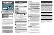
<strong>Black</strong> <strong>Hawk</strong><br />
Sikorsky AH-60<br />
Instruction Manual<br />
SPECIFICATIONS<br />
* Full Body Length: 61.5”<br />
* Body Width: 9.5” / 11.5”<br />
* Body Height: 9”<br />
* Weight: 11-14 lb<br />
* Engine: 60 Heli or 23cc heli Gasoline engine.<br />
Century Helicopter Products<br />
Designed and Developed in the USA<br />
2nd Edition March. 2001
Building Instructions for the <strong>Black</strong> <strong>Hawk</strong> scale body kit<br />
Introduction<br />
Congratulations on your purchase of the Century Helicopter Product’s <strong>Black</strong> <strong>Hawk</strong> scale<br />
helicopter body kit. This kit offers an easy entry into scale radio controlled helicopter flying<br />
whether you are just beginning into helicopters, getting into scale or an accomplished pilot.<br />
Though designed for the proven reliability of Century’s scale body design your new helicopter<br />
is sure to be an attention grabber at your local flying site.<br />
Warning<br />
This <strong>Black</strong> <strong>Hawk</strong> body must be assembled and installed closely in accordance with these<br />
instructions. Failure to do so could cause failures in the body structure or the helicopter<br />
mechanics. Such failures could result in serious injuries. It is recommended that if you are<br />
in doubt of your abilities, you should seek the assistance from experienced radio control<br />
modelers and associations. As a manufacturer, we assume no liability for the use of this<br />
product.<br />
Pre-assembly Information<br />
Upon opening the <strong>Black</strong> <strong>Hawk</strong> body kit, you will find the major fiberglass and clear component<br />
parts and hardware bags. Hardware is identified by size of the fastener or part. This<br />
is done for ease of assembly. Be careful when opening the bags as not to lose any hardware,<br />
whenever possible keep all screws in a container until you use them up through the<br />
assembly process. Care has been taken in the filling and packing of each bag. However,<br />
mistakes do happen. If there is a shortage or missing hardware, please contact us at:<br />
Century Helicopter Products<br />
523 Sinclair Frontage Road<br />
Milpitas, CA 95035<br />
(408)942-9525<br />
2
<strong>Black</strong> <strong>Hawk</strong><br />
Construction<br />
Manual<br />
This manual has been written to<br />
cover assembly of the <strong>Black</strong> <strong>Hawk</strong>.<br />
This instruction set is a supplement<br />
to your helicopter instruction<br />
manual, changes are listed below<br />
to the major areas that are affected<br />
by mounting.<br />
Every attempt has been made to<br />
ease the assembly of your <strong>Black</strong><br />
<strong>Hawk</strong>. At each step where there is<br />
a complex assembly, detailed<br />
written instructions are provided to walk you through the building process. Take a few<br />
minutes before each step to review the instructions, examine the hardware utilized in that<br />
step, and compare the drawings & pictures to your work in progress.<br />
Symbols used to help assist you in building the kit:<br />
Apply<br />
“Goop”<br />
Repeat Steps<br />
as specified<br />
Partially<br />
tighten<br />
Helpful<br />
Tip<br />
Special<br />
Attention<br />
Apply<br />
threadlock<br />
Purchased<br />
Separately<br />
Cut away<br />
Shaded<br />
Portion<br />
Hardware Description and Identification:<br />
M3x6 Self Tapping Screw<br />
M - metric<br />
3 - diameter<br />
6 - length<br />
M3x6 = 3x6mm and can refer to screws or fasteners.<br />
M3x10 Socket Cap Screw<br />
M - metric<br />
3 - diameter<br />
6 - length<br />
The tools and materials listed below are the<br />
minimum needed to build the <strong>Black</strong> <strong>Hawk</strong>.<br />
Screwdrivers - Slotted and Phillips head.<br />
Hex Key 2.5mm<br />
Long-Nosed Pliers.<br />
Paper Clip<br />
Scissors & Ruler<br />
Locktite (thread lock liquid)<br />
Clear cellophane or masking tape.<br />
Drill and drill bits (1/16”, 1/8”)<br />
Recommended Tools & Accessories<br />
In addition, the following will make<br />
assembly and setup easier, and prove<br />
useful later in your model toolbox:<br />
Primer and paint to match box art.<br />
5.0mm Open End Wrench.<br />
5.5mm Open End Wrench.<br />
7mm Open End Wrench.<br />
3
CN4005 <strong>Black</strong> <strong>Hawk</strong> Scale Fuselage Manual<br />
Warning<br />
The <strong>Black</strong> <strong>Hawk</strong> fuselage is designed to use Century’s flexible cable drive system, this requires that the mechanics chosen use a wire<br />
drive tail shaft or can be modified from a shaft or torque tube drive system. A belt drive system is not compatible. Consideration also<br />
must be taken when choosing a gyro as the demand from the cable drive system will require a lower gain setting and the heading hold<br />
gyro is generally not recommended from the high stress imposed on the tail. Century PG2000 gyro will work very well.<br />
Congratulations on purchasing Century’s magnificent scale fuselage of the UH-60 <strong>Black</strong> <strong>Hawk</strong>. The fuselage is manufactured from<br />
lightweight fiberglass using Epoxy resin with carbon fiber filament reinforcement at seams for extra strength. The fuselage has<br />
preprime coat surface and has the major open sections precut for convenience. All wooden parts are precut and labeled for easy<br />
identification. Semi-scale landing gear and wheels add that little extra that has made Century famous for their quality fiberglass scale<br />
fuselages.<br />
This instruction manual is a supplement to the full size plan detailing the location of the formers and the construction of the landing<br />
gear. Wherever possible this is to aid the modeler in the construction of their fuselage, however, due to the large number of helicopter<br />
mechanics available on the market, this instruction will only detail the general case. In many instances, additional modifications<br />
will be necessary to adapt to your helicopter.<br />
Section One Step 1.<br />
Unfold the full size plan on a flat surface. Insert the flexible<br />
cable into the brass tube (to keep the bend<br />
smooth, without kinks) and tape off at one<br />
end. Slowly bend the long brass tube to<br />
match the curvature on the drawing, make the<br />
bends gradual in intervals using your hands.<br />
Do not cut the length of the brass housing at<br />
this time, this will be done near the very end<br />
of installing the flexible cable drive system.<br />
Step 2.<br />
Locate F9 and F10, these formers are for mounting the tail gearbox to the elevated tail section. The F10 former is to be glued to the F9<br />
former with the offset notch to the front part of the F9 former. The basic design is to use Century existing vertical fin mounts on the<br />
tail gearbox to secure the tail gearbox to the wooden formers. Position and mark the holes for the vertical fin mount so the gearbox<br />
when bolted to the F10 former is either flush against the F9 former or is flush to the inside edge of F10 former. Depending on the tail<br />
gearbox, additional shims may be required. Drill through the plywood F10 former and deburr the holes.(see full size plan)<br />
Step 3.<br />
Disassemble and examine the tail gearbox, if possible install a grease fitting. This can be as simple as a small hole drilled into the<br />
gearbox housing and a matching screw that does not interfere with the internal workings of the gearbox to a brass tube epoxied flush<br />
to the inside surface with a cap commonly used to cap antennas.<br />
Step 3a.<br />
The following instructions detail installing Century’s tail<br />
garbox assembly<br />
Part# CN1109 into the elevated tail section of the fuselage.<br />
The finished solution will have the left half of the tail gearbox<br />
installed permanently with a removable top half of the right<br />
tail gearbox half. This will allow complete disassembly for<br />
maintenance of the tail gears and the flexible cable drive shaft<br />
and couplers.<br />
Step 3b.<br />
Initially assemble the F10 and F9 formers (do not use glue at<br />
this step) and install the tail gearbox assembly onto the F10<br />
former. Position and mark the location of the F9 former on the outside of the fuselage using pencil. Mark both above and below the<br />
former and the angle as exactly as possible. This location is ideal when the three bolts that fasten the tail gearbox assembly are all<br />
accessible and the tail output shaft is generally centered in the opening in the top of the tail section.<br />
4
Step 3c.<br />
Measure and mark the tail gearbox input shaft and use 3mm drill bit to open a small hole<br />
into the input shaft, so the shaft can fully engages the series of set screws on the flexible<br />
drive shaft. Using a countersink or a larger drill bit, enlarge the exit hole slightly where<br />
the flexible cable will exit the input shaft.<br />
Step 4.<br />
If installing another tail gearbox other than Century’s, follow the example detailed above<br />
and make the required modifications to mount into the tail section. It is very likely that<br />
the formers shown are better suited to mount smaller tail gearboxes.<br />
These need to be traced off the plans and cutout from 1/8” plywood<br />
(not included), note that the former is actually combined from three<br />
identical 1/8” formers bonded together. Position and mark the<br />
location of the formers on the outside of the fuselage using pencil.<br />
Step 5.<br />
A key element in installing a flexible cable drive system is to make<br />
sure the ends of the brass housing are properly secured. It is our<br />
recommendation to buy some additional º” plywood and cut two 1”<br />
diameter round circles. The F9 former has precut hole for the<br />
coupler to pass through, however in many installations the bare<br />
flexible cable will be exposed at this point (as when using the<br />
Century tail gearbox). Bond both wooden circles to each other and then bond below the F9 former using epoxy. Mark the centerline<br />
of the tail gearbox input shaft (simple when only one half of the gearbox is mounted to F10) and drill straight through with a drill bit<br />
that is 1/16” larger than the brass tubing.<br />
Step 6.<br />
Install the tail pitch lever to the tail gearbox with the necessary steel ball and mark the location for the flexible rudder pushrod (included<br />
with the fuselage) to pass through the F9 former. Again, drill the hole 1/16” larger than the size of the outside housing.<br />
Step 7.<br />
To prepare to permanently bond the F9 former into the elevated tail section, several things need to be completed. The brass tube, the<br />
rudder pushrod, and the left tail gearbox half need to be installed. First start with deciding the best method to bond in the former. The<br />
recommended choices are:<br />
- Drill several small holes in the fiberglass body along the centerline of the former, once the former is moved into final position, use<br />
Stabilit or epoxy that is injected using a syringe inserted into each hole while forcing the fiberglass slightly away from the wood<br />
former. As the syringe is remove the fiberglass compresses against the wood former forcing any excess glue to the edges. Repeat<br />
process for all holes.<br />
- Using a saw or moto-tool grind vertical slots in the edge of the former spaced at º” apart. Measure and mark the inside wall where<br />
the final position of the top surface of the former. Once ready, use a Q-tip or applicator and apply Stabilit or epoxy above the<br />
mark on the inside of the fiberglass and to the outside edge of the former. Wipe any excess from the edge leaving adhesive inside<br />
the slots. Move the assembly into final position, as the former passes through the glue previously applied to the inside of the tail<br />
section it will form a solid bond to the former.<br />
- A variation on the first approach is to grind a slot through the centerline of the former 1/16-3/32” deep and drill only a few holes<br />
through the fiberglass. As the adhesive in injected, it will flow around the former and bond it in place.<br />
Step 8.<br />
The F9 former needs to be test fitted into the inside of the tail section. Inspect the internal opening and grind or sand any excess<br />
material that will interfere with test fitting the former. To make this task simpler, tie a cord through the pushrod and drive shaft hole to<br />
make removing the former simple. Sand the edges until the former can be moved into the final position with your fingers without<br />
excessive force. Once satisfied, stop here.<br />
Step 9.<br />
Before the F9 former is permanently bonded in place the same work needs to be performed on the remaining formers (F8, F6, F5 &<br />
F4) that will position the brass housing and the rudder pushrod housing. Inspect and grind or sand any material that will interfere with<br />
installing these formers. Also verify that the holes match the brass housing and the rudder pushrod, make any changes at this time.<br />
Each former needs to be prepared and test fitted according to your preferred gluing method, however; access to these formers is much<br />
5
simpler and at minimum one side of each former can be properly reinforced by filleting.<br />
Step 10.<br />
Wood block F7 needs to be prepared to mount the wire tail strut to the inside of the fuselage in-between former F8 and F6. Compare<br />
to the full size plan and mark the location for the F7 wood block in pencil on the tail section. Grind or sand the position on the inside<br />
of the tail section to get a good bond. Also align the strut and mark and cut a slot where the wire will exit the fuselage tail section. It<br />
is important to make this slot longer than necessary to allow the wire to flex or deflect when landing. The exact length can be finalized<br />
after the model is completed and tested. Do not glue any formers in place at this time. Stop here.<br />
Step 11.<br />
Compare, measure and mark the final position of the F8 former on the outside of the fuselage. Remember to do a final wipe down<br />
with acetone on the fiberglass parts before gluing, to clean and get the best bonding possible. Following the chosen gluing method,<br />
permanently bond the F8 former in place.<br />
Step 12.<br />
Permanently glue the F7 wood block in position capturing the wire tail strut.<br />
Step 13.<br />
Carefully feed the brass housing and the rudder pushrod through the F8 former, up and out<br />
through the opening in the top of the elevated tail section. Do not bond the brass housing or the<br />
pushrod to F8 at this time.<br />
Step 14.<br />
Before the end of the flexible cable can be used, the last 5/8-3/4” of the cable needs to be “tinned”. Silver<br />
Solder is highly recommended but Rosin Core Solder can be substituted, heat the end of the cable with a<br />
soldering iron until the solder takes to the cable. Continue until an even silver coating has been applied.<br />
If the end will no long fit into the coupler, gently file along the length of the end until it can be fully<br />
inserted into the coupler.<br />
F7 Tail Strut<br />
Mount<br />
Step 15.<br />
With both the brass housing and the pushrod extended through the top opening in the elevated tail, test fit the tail components one last<br />
time. Assemble the tail gearbox with the coupler and attach the prepared end of the cable. Slide the end of the brass housing into the<br />
modified F9 former and insert the pushrod housing. Make the connection for the end of the rudder pushrod to the ball on the tail pitch<br />
lever. Inspect and verify that the end of the brass housing has a gap of 3/16-1/4” before contacting the coupler, measure and write<br />
down the exact position, noting the amount if any, that the brass housing is protruding past the F9 former. Measure and write down the<br />
same information for the rudder pushrod housing, remember that the final position must allow complete end to end travel of the pitch<br />
plate assembly.<br />
Step 16.<br />
Depending on the type of tail gearbox will modify the order of the following instructions to permanently bond the F9 and F10 former<br />
in place.<br />
Step 16a.<br />
For the Century tail gearbox, (Part# CN1109) bond the F10 former into the F9 former.<br />
Place the formers (still referred to as F9) into the cavity and reposition and bond the brass<br />
housing and the rudder pushrod housing in place using slow CA, or Epoxy using the<br />
information collected in Step 15. Attach the left gearbox half to the F10 former using<br />
socket head bolts and lock nuts (not included).<br />
Choice: 1. Cut the top off the fiberglass tail to install the gearbox assembly then reattach<br />
the top of the elevated tail.<br />
2. Use a heat gun to soften the top section, flex the opening to allow installation<br />
of the gearbox. Once the gearbox is inside, let the fiberglass cool to return to<br />
the original shape.<br />
Step 16b.<br />
Once the left half of the gearbox is inside the top of the elevated tail, move the gearbox with the F9 former into the final position. This<br />
position corresponds with having direct access to all the hex bolts that secure the right gearbox half in place. Using the preferred<br />
6
method to bond formers, permanently glue the F9 former into the tail section.<br />
Step 16c.<br />
Slide the flexible cable out through the end of the brass housing and attach the cable to the tail coupler shaft (this can be done outside)<br />
assembled onto the tail gearbox input. Slide the shaft assembly into the tail and engage the ball bearings while mating the tail output<br />
shaft. Grease the gearbox at this stage.<br />
Step 16d.<br />
Re-attach the right gearbox side and tighten the three hex bolts.<br />
Step 17.<br />
If another tail gearbox assembly is being installed, read the previous step to become familiar with the process and position and<br />
permanently bond the formers in place.<br />
Step 18.<br />
Using a ruler, estimate the center of the tail output shaft and make pencil marks on the edge of the opening. Match the tail cap and<br />
transfer the marks. Using the ruler, mark the center of the shaft and drill or grind out a º” diameter hole. This will be further enlarged<br />
to include clearance for the tail pitch lever and the tail pitch plate. Complete this at this time.<br />
Step 19.<br />
Re-attach the rudder pushrod ball link to the tail pitch lever.<br />
Step 20.<br />
Before installing the F6 former, glue the brass housing and the rudder pushrod housing to the F8 former. Also reinforce the former by<br />
forming a fillet of epoxy around the edge of the former and the fiberglass wall.<br />
Step 21.<br />
Take the time to reinforce the tail wire mount F7, using fiberglass cloth (not included) cut and bond a section of cloth over the F7<br />
wood mount and extend 3/8-1/2” away from the mount. A method to reduce the vibration of the brass housing is to inject expandable<br />
foam into the hollow cavities between the formers. This method has been proven to effectively dampen vibration, however; overfilling<br />
a section can bulge the shape of the tail and remember to only inject the foam into the inside space between permanently bonded<br />
formers.<br />
Step 22.<br />
Insert and slide the F6 former into final position and permanently bond in place using the chosen method. Remember to reinforce the<br />
edge with a fillet to the fiberglass. The F5 former is to support the rudder pushrod according to the original full size plans. Note that<br />
the rudder servo no longer is required to be mounted directly behind the mechanics, the general rule is to make the rudder<br />
pushrod as short as possible to reduce slop in the control surface. The exact servo position is the modeler’s choice and is no<br />
longer detailed in these instructions. Please also note that in the redesign, the floor section of the main fiberglass body has been<br />
structurally reinforced and has the angle built into the floor eliminating the need for shaped hardwood rails as shown on the full size<br />
plans.<br />
Step 23.<br />
The elevator on this fuselage is best mounted in a fixed position following the general rule for model helicopters that the fewer moving<br />
non-flying parts the better. However; for the ambitious modeler, the elevator could be hinged in a manner that would allow some<br />
limited angle adjustment for forward flight.<br />
Section Two<br />
Step 24.<br />
Start by thoroughly cleaning the main fiberglass fuselage section with mild detergent and water. Let dry and wipe all fiberglass<br />
surfaces. Position the main helicopter mechanics with the main rotor head and tail boom assembly removed so the main shaft is<br />
centered in the hole in the top hatch. Using pencil, mark the four landing gear locations with tick marks. Also mark the opening for<br />
the cooling fan shroud exhaust hole. Remove and complete the crosshairs, remember to use a ruler to verify the landing gear marks<br />
and the real measurements off the mechanics. Drill the four mounting locations and open the cutout for the cooling fan shroud<br />
exhaust. A simple method to open a large area in fiberglass is to drill the corner holes and use a moto-tool and a cutoff wheel to<br />
connect the holes. Final shaping can be done with a grinding stone attachment or a file.<br />
7
Step 25.<br />
The wooden parts in the main fuselage section are all susceptible to fuel contamination and should be fuel proofed with paint that will<br />
match the interior or with epoxy thinned with rubbing alcohol. Either way these wooden parts need fuel proofing.<br />
Step 26.<br />
To prepare the main landing gear assembly, start by opening the ends of the<br />
landing gear fairing on both sides , be careful here to open only the end<br />
while leaving the flange in place that keys the fairing cap.<br />
Locate and position the F1 wooden mount, note that the hole in forward<br />
face is higher than the rear face. Use a file to do any final shaping to<br />
position the F1 mount. Once satisfied with the fit, bond the F1 mount in<br />
place using epoxy, being careful to have both holes on the outside of the<br />
fuselage. Once dry, reinforce the F1 mount by adding fiberglass cloth (not<br />
included) and epoxy.<br />
Step 27.<br />
Following the drawings on the full size plan, mark the top and bottom edges<br />
of the F3 wood block with pencil and do any final fitting that may be needed<br />
to install on each side of the F3 wood block. Thoroughly roughen the fiberglass<br />
surface to be bonded with #320 grit sandpaper. Go ahead and permanently bond<br />
formers F2 & the F3 wood block in place on both sides of the fuselage. A simple<br />
tip here to mark the location of the hole below the F3 wood block and through the<br />
fuselage is to insert a hex key through the top and let it fall and stop on the glass.<br />
Now mark and drill the two vertical holes where the vertical landing gear legs will<br />
exit the fuselage. It is best to oversize these holes to allow for slight movement of<br />
the landing gear, without damaging the fuselage side.<br />
Step 28.<br />
Using the wheel collars and the rubber dampers according to<br />
the full size plans, assemble the landing gear with the wooden<br />
blocks to get a better understanding of how the landing gear<br />
will function. While supporting the fuselage from the center,<br />
position the one vertical landing gear strut (with 90 degree bend)<br />
and tape to the horizontal landing gear strut (with 60 degree<br />
bend) together. Position the tape where the wire is shown on<br />
the full size plan. The intention is to silver soldier these parts<br />
together which can create a difficulty in removing the landing<br />
struts at a later time. The key to installing and removing the<br />
assembled struts is to loosen and remove the end wheel collar<br />
from the horizontal and vertical struts and to flex the assembly<br />
down and rearward. Both struts will flex enough to clear the<br />
horizontal strut from the F1 wooden block. Once satisfied with<br />
the method to remove the landing gear, use steel wire (not<br />
included) wrap the length of the legs that overlap and tack with<br />
CA. Using silver soldier, permanently soldier the two legs together<br />
overlapping the wrapped wire. To improve the look, simple balsa<br />
strut covers can be made to look more scale. Once completed,<br />
remove the landing gear until the fuselage has been painted.<br />
Rubber<br />
isolator<br />
Using silver<br />
soldier<br />
collar<br />
collar<br />
Wing<br />
Final landing strut installation:<br />
Guide the vertical and horizontal strut close to the wood mounts and<br />
slide one wheel collar followed by one rubber isolator. Insert both<br />
ends together into the wood mounts and flex slightly to slide into<br />
final position. Once the struts are passed the wood mount, slide<br />
another rubber isolator and wheel collar onto the end of each strut<br />
from the inside of the fuselage. Lastly, set the high of each strut by<br />
supporting the center of the fuselage and measuring from the table<br />
surface to each strut axle. Slide one wheel onto each side of the<br />
fuselage and attach using one wheel collar.<br />
8
Step 29.<br />
There are 24 pieces of 3/8” square plywood screw mounts and 24 3x8mm self tapping screws. These are to attach the top hatch and<br />
the tail cover to the main fuselage body. There is no set rule for using all of these parts to attach the hatches. Start by taping the hatch<br />
to the main fuselage using masking tape. Using a ruler, mark lines that overlap the top hatch and the main fuselage that are spaced 3-4<br />
inches apart along the outside edge of the hatch. Measuring in from the edge of the hatch, mark and drill through the hatch and the<br />
main fuselage using a 3/32” drill bit. Once all the holes are made, remove the top hatch and roughen the surface on the inside at each<br />
hole location using sandpaper. One at a time, bond the 3/8” plywood squares centered over each hole from the inside using slow CA<br />
or epoxy. Let completely dry and drill though the wood using the 3/32” drill bit. Using one self tap screw, form the threads in all the<br />
plywood blocks. Finally, apply one drop of the fast CA glue to each hole to harden the wood. Repeat this process to mount the tail cap<br />
to the elevated tail section.<br />
Step 30.<br />
Carefully inspect the windshield and the cheek windows, there is a fine trim line on each clear window. Using a marker, follow the<br />
trim line to improve the visibility. For extra precaution, draw a second line beyond the first line and trim each part. This preliminary<br />
step allows test fitting of the slightly oversized window to see exactly how much additional trimming is necessary. In some instances,<br />
the clear part can be bonded in place as is without further trimming. Once each part is test fitted, use rubbing alcohol to remove any<br />
residual marker from the clear part. Stop here until after the fuselage has been painted to install the clear parts.<br />
Final installation of clear parts:<br />
Once the fuselage is painted, clean and wipe acetone (do not get any on the painted surface) on the inside surface of the window<br />
openings on the fuselage to be bonded. Using “Goop” or “R/C 56 windshield adhesive” commonly found in the local model hobby<br />
shop or hardware store apply an even coat to the edge of the windshield. Be careful not to get any on the surface of the clear part that<br />
you want to keep clear as this adhesive will create a blemish that cannot be removed.<br />
Step 31.<br />
Installation of the side doors can be done in the closed or open position. In either position, the doors are bonded to the main fuselage<br />
using epoxy. Remember to install after painting and prepare the contact edges by sanding through the paint before permanently<br />
bonding in place.<br />
Step 32.<br />
Place the helicopter mechanics into the center section of the fuselage with the muffler fitted to the engine. Measure, mark and drill/<br />
grind the hole for a flexible exhaust diverter (not included) to evacuate the exhaust from the fuselage. Do not attempt to route the<br />
exhaust to the “scale” positions as the extra length of the exhaust diverter will cause unpredictable and inconsistent engine<br />
performance that is highly undesirable in a scale fuselage.<br />
Step 33.<br />
The next major task is to attach the tail section to the main fuselage section. This can be done after the fuselage is painted but it is<br />
recommended to complete before to allow filling and blending of the tail to the main fuselage. Start by sanding through the surface of<br />
the mating surface on the main fuselage section and repeat for the inside surface of the tail section. Test fit the joint to make sure the<br />
two parts match correctly when brought together. Once satisfied, mix up plenty of Stabilit or epoxy and coat one surface with glue<br />
and slide the two parts together. A little preparation here can go a long way, sight the front to back alignment and look at the side view<br />
for proper alignment. Secure both the main fuselage and the tail assembly in place using long strips of masking tape. Make adjustments<br />
as necessary to get the perfect alignment.<br />
Step 34.<br />
Insert the tail coupler onto the tail transmission output shaft on the mechanics.<br />
Mark and grind the appropriate flat spots positioned at 90 degrees to one<br />
another on the tail shaft. Also remove any extra shaft length using the<br />
moto-tool with a cutoff wheel. Remember to deburr the end of the tail<br />
shaft when finished and to slightly countersink the entrance hole where<br />
the flexible cable will enter the coupler.<br />
Step 35.<br />
Test fit the F4 former into position on the main fuselage,<br />
some trimming or grinding of the fuselage may be<br />
necessary to get a good fit. Install and bolt the main<br />
helicopter mechanics into the main fuselage. Guide the F4<br />
position flush<br />
against the<br />
mechanics.<br />
9
former and insert the brass housing through one of the large side holes. Position the F4 former behind the mechanics and initially<br />
position flush against the mechanics. While viewing from above, mark on the brass housing the position that will be approximately 1/<br />
2” past the end of the tail coupling. Trim the brass housing at the marked location and remove the mechanics and reposition the brass<br />
housing now inserted into the center hole in the F4 former.<br />
Step 36.<br />
Measure and mark past the beginning of the flexible cable as it would be positioned inside the tail coupling. Again, remove the<br />
mechanics. Trim the flexible cable using the cutoff wheel on the moto-tool. Do not try to use side cutters to cut the cable as you<br />
will damage the cable. Once trimmed, the last 5/8-3/4” of the cable needs to be “tinned”. Silver Solder is highly recommended but<br />
Rosin Core Solder can be substituted, heat the end of the cable with a soldering iron until the solder takes to the cable. Continue until<br />
an even silver coating has been applied. If the end will no long fit into the coupler, gently file along the length of the end until it can<br />
be fully inserted into the coupler.<br />
Final assembly.<br />
Once painting is completed this will be the last step in assembling the fuselage. Insert the flexible cable and secure two 4x4mm set<br />
screws using threadlock.<br />
Step 37.<br />
Included in the kit are two “L” channel brackets. These are to brace the mechanics to the F4 former. As helicopter mechanics have<br />
evolved over the last decade, there may or may not be a vertical surface to attach the bracket to the mechanic, in this case some<br />
fabrication is necessary to make the connection. While holding the F4 former flush against the mechanics vertical, make two marks in<br />
pencil where the former will be mounted on the top and a mark inside the floor of the fuselage. When satisfied with the fit, permanently<br />
bond the F4 former in place using the preferred bonding method. Align the “L” brackets and mark and drill the mounting<br />
locations. Using socket head cap screws and lock nuts (not included) mount the “L” bracket to both the mechanics and the F4 former.<br />
Final installation of the mechanics.<br />
Once the flexible cable has been attached the “L” brackets can be attached.<br />
Step 38.<br />
This can be done after the fuselage is painted but it is recommended to complete before to allow filling and blending of the fairing cap<br />
to the main fuselage. Start by sanding through the surface of the mating surface on the main fuselage fairing stub and repeat for both<br />
sides. Test fit the joint to make sure the two parts match correctly when brought together. Once satisfied, mix up Stabilit or epoxy and<br />
coat one surface with glue and slide the two parts together<br />
Section Three: : The final section covers painting the scale fuselage.<br />
A couple of topics can be discussed at this time, the fuselage is molded using epoxy resin and a combination of glass cloth and glass<br />
strips. Fiberglass fuselages have always been criticized as brittle, difficult to work with and difficult to repair. All of these statements<br />
are false, but it depends on who the person’s is and their experiences.<br />
First off, in strength compared to the space age canopies that are common on most pod and boom helicopters there is no contest. This<br />
plastic material is virtually indestructible at the penalty of being virtually un-paintable without specialized and expensive automotive<br />
primers and paints, there is also a very limited range of colors available. The reason you are reading this page is that you have come to<br />
your senses and wanted to fly a model that looks and holds all the prestige of a real helicopter.<br />
Flexibility<br />
A wonderful attribute of fiberglass is in its flexibility. Century and Funkey take care and pride in craftsmanship that goes into every<br />
fuselage. However, fiberglass parts will migrate while inside the shipping box. When two mating components are brought together<br />
and they do not align or mate, the culprit is a warped part. Many become upset and wish to lay blame but dealing with this is very<br />
simple when explained a simple procedure. Using a heat gun set at the high setting at a distance of 1-2 feet away, evenly heat the<br />
warped part until the outside surface is hot to the touch and the part has become pliable (flexible). Using adhesive tape, mate the two<br />
fiberglass parts together and let both parts sit until both parts have reached room temperature. Remove the tape and now both parts are<br />
stable and match one another. In some instances, depending on the location of the warp, the part may need to be held in an overextended<br />
position to achieve the proper shape when the part is finished.<br />
10
Dealing with Fiberglass.<br />
Difficult to work with, I disagree. Fiberglass is easier to repair than you think. Using today’s CA type of adhesives, a severe crack in<br />
a fuselage can be simply fixed and the repaired section is much stronger than in its original state. Add touchup paint and no one would<br />
ever know I had been damaged. There is a limit to this type of thinking where purchasing the replacement fiberglass part is simply<br />
cheaper and less work than performing major reconstructive surgery.<br />
The Paint Job.<br />
There is no magic to a good paint job, the true secret is time, patience and common sense. A modeler who thinks that they can throw<br />
paint onto a fuselage Friday night before flying on Sunday is dreaming, the helicopter would be flyable but even that is a stretch. The<br />
average modeler will spend the better part of a month to apply a good clean paint job.<br />
Preparing the fuselage for painting.<br />
After opening the kit version of the fuselage, examine all the fiberglass components to see where work needs to be done to allow a<br />
simple “bring up” of the fuselage. “Bring up” describes the necessary steps to complete all the jobs in order to start priming the<br />
fiberglass parts. Typical work that is done at this stage is rough sanding on seams and jointed components, filling of surface imperfections,<br />
adding panel lines and rivets, cutting required holes and preparation for priming.<br />
Step 39.<br />
Start by thoroughly washing all fiberglass parts in mild detergent and water, this will remove any residue remaining from the molding<br />
process. Next wipe down all the parts with Acetone (from the hardware store). The Acetone will remove all traces of oil or grease that<br />
will affect the adhesion of two fiberglass parts or between the paint and the fiberglass. Now using steel wool or an abrasive pad<br />
commonly used for scrubbing dishes, scuff all surfaces that will be joined or receiving paint. What is important to note here is that we<br />
are breaking through the topmost resin surface and creating the best surface for adhesive or primer to adhere to. The prepared finish<br />
will have very fine score marks usually seen when the part is held to the light at a slight angle.<br />
Step 40.<br />
This is the time to rough sand any accessories or small parts, using the 320 grip sandpaper, that will be assembled and attached at<br />
different positions on the fuselage. These can be marking lights, engine exhausts, scale fuel tanks, horizontal and vertical stabilizers,<br />
guns, antenna or any scale details being bonded to the fuselage. These accessories should be test assembled to make sure that all parts<br />
are prepared, and you will be able to see any problems that may arise in trying to paint these parts. Some thought should be put into<br />
how to hold the part as it is being painted. Go ahead and bond these parts at this time using the slow CA glue. A quick note on<br />
adhesives, as the fuselage resin is epoxy, go ahead and use any regular 5-30 minute epoxies to bond two fiberglass components<br />
together or unlike substances, like wood or metal to the fiberglass.<br />
Step 41.<br />
Once the detail parts have been built into the sub assemblies are ready to paint, use a filler in sections that have gaps or slight surface<br />
imperfections, occasionally there are voids (air bubbles in the resin) that occur near the surface that need to be filled. There are allot of<br />
good fiberglass fillers on the market, it is best to check with your local hobby shop to get a recommended product. Try to stay away<br />
from porous fillers designed for wood as they will shrink and are not a good choice for larger areas.<br />
Step 42.<br />
Most major windows and accessory holes have been precut by Century, leaving only those that have a user dependency like the type of<br />
exhaust system used on the helicopter or the exact exit position for the cooling fan shroud.<br />
Step 42a.<br />
When making cutouts or holes in the surface of the fiberglass the best procedure is to drill a pilot hole using the 1/16” drill bit at<br />
corners or along a curve. Start with using a permanent marker to draw the opening or window. The pilot holes serves to avoid leaving<br />
sharp corners which given the nature of a helicopter will be the focal point for stress cracking originating from the corner. Once the<br />
holes have been made, use the moto-tool for all other roughing cuts. The cut off wheel is the best for straight lines and either the<br />
sanding drum or the curved stone is used for smoothing edges. If the cut out is a window, do not use the moto-tool for the final work.<br />
Switch to a sanding blocks, square blocks of various sizes for straight edges and round dowels for rounded corners.<br />
Step 42b.<br />
In the case of the exhaust opening which will end up being 1/8” larger across the outside diameter of the exhaust pipe that extends<br />
below the bottom of the fuselage. After drawing the circle, use grinding stone and move in small circles until the hole is at the size<br />
wanted.<br />
Step 43.<br />
11
Priming the fuselage accomplishes two tasks: firstly, the primer paint is designed to aggressively adhere to the surface being painted<br />
and provide the best surface for the colored paint to adhere to; secondly, all surface imperfections will become visible. Depending on<br />
the particular imperfection, light sanding and the second priming will take care of 90% of the highly visible problems. The remaining<br />
10% need to be filled, let dry, sanded and then sprayed with the second coat of primer. The primer process will be repeated until the<br />
surface is as perfect as your patience and time permit.<br />
Step 44.<br />
Select your paint color and follow the directions on the particular brand of paint being used as each manufacturer has different<br />
requirements.<br />
Step 45.<br />
Spray cans vs Airbrushed finishes. The preference is left the to the modeler, many good paint jobs have been accomplished using the<br />
spray cans however in the long run a good spray can finish requires more attention than using an airbrush. The answer is simple, you<br />
want a professional looking fuselage, not want a flying brick. We need not even think or mention any type of paintbrush larger than º”<br />
wide.<br />
As for selecting the type of paint there are two different schools. For beginners, visit your local hobby shop and as their opinion on<br />
painting fiberglass. On a general note, polyurethane is always a very safe paint that is fuel proof. The key is the last point, a perfect<br />
paint job can be easily ruined by spilling raw 15-30% fuel accidentally. There is no paint manufacturer who will tell you that their<br />
product will resist 30% fuel for very long and for the most part the fuselage is only exposed to the oil residue from the burned exhaust.<br />
We all know very well that in tight, restricted fuelling areas like a scale helicopter are prone to having fuel spills from time to time.<br />
For this reason, it is recommended to paint the area around the engine and fuel tank, especially the edges of the fiberglass opening<br />
where paint runs will start. A good hobby shop will carry a bottle of clear polyurethane in liquid form just for this purpose. Thinned<br />
epoxy works well in a pinch.<br />
The other very common paint used for models is automotive paints, these by nature are not fuel proof and will require the final top<br />
coat to be a polyurethane or equivalent. This usually insinuates that the paint is being airbrushed on to the surface of the fuselage.<br />
Good luck with your paint schemes and painting job undertakings.<br />
12
Optional Accessories to Complete your <strong>Black</strong> <strong>Hawk</strong><br />
To truly make your <strong>Black</strong> <strong>Hawk</strong> scale, the high performance 4 blade scale rotor head is available.<br />
This rotor head consists of an all metal assembly, dual ball bearing aluminum main blade<br />
grips which feature the I.D.G. system (Individual grip damping) to dampen each blade individually<br />
to eliminate turbulence vibration which is crucial for super smooth flying with Century’s<br />
multiple rotor blades. Century makes all the components required for this conversion: head<br />
assembly, 4 blade swashplate, custom follower and main rotor blades.<br />
CN1104 Multi 4 blade rotor head (60/90 to Gasoline size)<br />
CN1107-4 Swashplate - 4 blade (10mm shaft )<br />
CN1108 Swashplate Follower (8 & 10mm shaft) -<br />
Keeps swashplate timed to main blades<br />
CN1109 Scale tail gear box assembly<br />
CN1202 4 blade multi tail unit (fits most helicopters)<br />
CN2328B 4 Blade Multi Main Blade Set (600mm)<br />
CN4005R<br />
<strong>Black</strong> <strong>Hawk</strong> Replacement Part List<br />
CN4005F<br />
CN4005W<br />
CN4005T<br />
CN4005F<br />
CN4005H<br />
CN4005B<br />
CN4005D<br />
CN4005C<br />
CN4005H<br />
CN4005F<br />
CN4005R<br />
CN4005T<br />
CN4005W<br />
<strong>Black</strong> <strong>Hawk</strong> blue print & manual<br />
Tail drive shaft & mount unit<br />
Canopy and windshield<br />
Hardwear and landing gear parts<br />
Fiberglass main fuselage body & doors<br />
Fiberglass tail boom<br />
Fiberglass top cap<br />
Wood parts<br />
All rights reserved. No part of this publication may be reproduced, stored in a retrieval system or<br />
transmitted in any form or by any means, electronic, mechanical, photocopying, recording or<br />
otherwise, without the prior written permission of the publisher, Century Helicopter Products.