Black Hawk
CN4005 BlackHawk - Centuryhelimedia.com
CN4005 BlackHawk - Centuryhelimedia.com
- No tags were found...

Create successful ePaper yourself
Turn your PDF publications into a flip-book with our unique Google optimized e-Paper software.
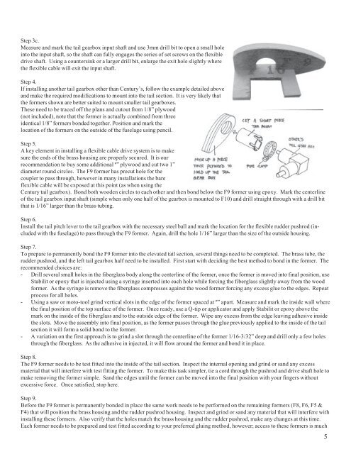
Step 3c.<br />
Measure and mark the tail gearbox input shaft and use 3mm drill bit to open a small hole<br />
into the input shaft, so the shaft can fully engages the series of set screws on the flexible<br />
drive shaft. Using a countersink or a larger drill bit, enlarge the exit hole slightly where<br />
the flexible cable will exit the input shaft.<br />
Step 4.<br />
If installing another tail gearbox other than Century’s, follow the example detailed above<br />
and make the required modifications to mount into the tail section. It is very likely that<br />
the formers shown are better suited to mount smaller tail gearboxes.<br />
These need to be traced off the plans and cutout from 1/8” plywood<br />
(not included), note that the former is actually combined from three<br />
identical 1/8” formers bonded together. Position and mark the<br />
location of the formers on the outside of the fuselage using pencil.<br />
Step 5.<br />
A key element in installing a flexible cable drive system is to make<br />
sure the ends of the brass housing are properly secured. It is our<br />
recommendation to buy some additional º” plywood and cut two 1”<br />
diameter round circles. The F9 former has precut hole for the<br />
coupler to pass through, however in many installations the bare<br />
flexible cable will be exposed at this point (as when using the<br />
Century tail gearbox). Bond both wooden circles to each other and then bond below the F9 former using epoxy. Mark the centerline<br />
of the tail gearbox input shaft (simple when only one half of the gearbox is mounted to F10) and drill straight through with a drill bit<br />
that is 1/16” larger than the brass tubing.<br />
Step 6.<br />
Install the tail pitch lever to the tail gearbox with the necessary steel ball and mark the location for the flexible rudder pushrod (included<br />
with the fuselage) to pass through the F9 former. Again, drill the hole 1/16” larger than the size of the outside housing.<br />
Step 7.<br />
To prepare to permanently bond the F9 former into the elevated tail section, several things need to be completed. The brass tube, the<br />
rudder pushrod, and the left tail gearbox half need to be installed. First start with deciding the best method to bond in the former. The<br />
recommended choices are:<br />
- Drill several small holes in the fiberglass body along the centerline of the former, once the former is moved into final position, use<br />
Stabilit or epoxy that is injected using a syringe inserted into each hole while forcing the fiberglass slightly away from the wood<br />
former. As the syringe is remove the fiberglass compresses against the wood former forcing any excess glue to the edges. Repeat<br />
process for all holes.<br />
- Using a saw or moto-tool grind vertical slots in the edge of the former spaced at º” apart. Measure and mark the inside wall where<br />
the final position of the top surface of the former. Once ready, use a Q-tip or applicator and apply Stabilit or epoxy above the<br />
mark on the inside of the fiberglass and to the outside edge of the former. Wipe any excess from the edge leaving adhesive inside<br />
the slots. Move the assembly into final position, as the former passes through the glue previously applied to the inside of the tail<br />
section it will form a solid bond to the former.<br />
- A variation on the first approach is to grind a slot through the centerline of the former 1/16-3/32” deep and drill only a few holes<br />
through the fiberglass. As the adhesive in injected, it will flow around the former and bond it in place.<br />
Step 8.<br />
The F9 former needs to be test fitted into the inside of the tail section. Inspect the internal opening and grind or sand any excess<br />
material that will interfere with test fitting the former. To make this task simpler, tie a cord through the pushrod and drive shaft hole to<br />
make removing the former simple. Sand the edges until the former can be moved into the final position with your fingers without<br />
excessive force. Once satisfied, stop here.<br />
Step 9.<br />
Before the F9 former is permanently bonded in place the same work needs to be performed on the remaining formers (F8, F6, F5 &<br />
F4) that will position the brass housing and the rudder pushrod housing. Inspect and grind or sand any material that will interfere with<br />
installing these formers. Also verify that the holes match the brass housing and the rudder pushrod, make any changes at this time.<br />
Each former needs to be prepared and test fitted according to your preferred gluing method, however; access to these formers is much<br />
5