Tiller/Cultivator
Owner's Manual - Mantis
Owner's Manual - Mantis
- No tags were found...

Create successful ePaper yourself
Turn your PDF publications into a flip-book with our unique Google optimized e-Paper software.
401710 <strong>Tiller</strong> Red 20pgs_???code <strong>Tiller</strong> Grn 5/24/10 11:05 AM Page 1<br />
<strong>Tiller</strong>/<strong>Cultivator</strong><br />
OWNER’S MANUAL
401710 <strong>Tiller</strong> Red 20pgs_???code <strong>Tiller</strong> Grn 5/24/10 11:05 AM Page 2<br />
WELCOME TO THE WORLD<br />
OF MANTIS GARDENING!<br />
Here’s your new MANTIS <strong>Tiller</strong>...<br />
the lightweight wonder that “Makes<br />
Gardening Easier.”<br />
Unlike big tillers, your MANTIS <strong>Tiller</strong><br />
weighs only 20 pounds. So it lifts easily,<br />
handles smoothly, tills and weeds precisely.<br />
And, unlike other small tillers, it features<br />
serpentine tines that churn soil up to ten<br />
inches deep. It creates a soft, smooth seed<br />
bed, even in problem soil.<br />
Once you know how to use your tiller<br />
correctly, we guarantee you’ll love it. So<br />
first, please read this manual. It shows, step<br />
by step, how to use your tiller safely. Plus,<br />
it shows how the MANTIS Border Edger<br />
can make light work of your edging needs.<br />
If you have questions about any topic in<br />
this Manual, or if you wish to order<br />
MANTIS Attachments, contact your local<br />
authorized MANTIS dealer.<br />
TABLE OF CONTENTS<br />
Safety Rules & Warnings . . . . . . . . . . . . . . . . .3-4<br />
Safety Decals . . . . . . . . . . . . . . . . . . . . . . . . . . .3<br />
Engine & Fuel Warnings . . . . . . . . . . . . . . . . . .4<br />
Assembly and Mixing Fuel . . . . . . . . . . . . . . .5-7<br />
Starting . . . . . . . . . . . . . . . . . . . . . . . . . . . . . .7-8<br />
Additional Information . . . . . . . . . . . . . . . . . . .8<br />
What to Do Just in Case . . . . . . . . . . . . . . . . . .8<br />
Getting to Your Garden . . . . . . . . . . . . . . . . . . .9<br />
Tilling . . . . . . . . . . . . . . . . . . . . . . . . . . . . . . . . .9<br />
Service Maintenance Guide & Specifications .10<br />
Tine Positioning . . . . . . . . . . . . . . . . . . . . . . . .11<br />
2<br />
Tilling/Cultivating . . . . . . . . . . . . . . . . . . . . . .11<br />
Maintenance . . . . . . . . . . . . . . . . . . . . . . . .12-13<br />
Storage . . . . . . . . . . . . . . . . . . . . . . . . . . . . . . .14<br />
Trouble Shooting . . . . . . . . . . . . . . . . . . . . . . .15<br />
Using The Border/Edger Attachment . . . . . . . .16<br />
MANTIS <strong>Tiller</strong> Assembly Layout . . . . . . . . . . .16<br />
Engine Parts Assemblies . . . . . . . . . . . . . . .17-19<br />
Emission<br />
Control Warranty Statement . . . .19-Back Cover<br />
Limited Warranty Information . . . . .Back Cover
401710 <strong>Tiller</strong> Red 20pgs_???code <strong>Tiller</strong> Grn 5/24/10 11:05 AM Page 3<br />
SAFETY RULES & WARNINGS<br />
You will notice throughout this Owners Manual Safety Rules and Important Notes. Make sure you<br />
understand and obey these warnings for your own protection.<br />
I. Special Safety Information<br />
! WARNING • DANGER !<br />
ATTENTION: THIS SYMBOL POINTS<br />
OUT OUR IMPORTANT<br />
SAFETY INSTRUCTIONS.<br />
WHEN YOU SEE THIS SYMBOL,<br />
HEED IT’S WARNING!! STAY ALERT!!<br />
II. Safety & Warnings<br />
!<br />
! WARNING • DANGER !<br />
TO REDUCE THE POTENTIAL FOR ACCIDENTS,<br />
COMPLY WITH THE SAFETY INSTRUCTIONS<br />
IN THIS MANUAL.<br />
FAILURE TO COMPLY MAY RESULT IN SERIOUS<br />
PERSONAL INJURY, AND/OR EQUIPMENT<br />
AND PROPERTY DAMAGE.<br />
! WARNING • DANGER !<br />
IMPROPER USE OR CARE OF THIS TILLER OR FAILURE TO WEAR PROPER<br />
PROTECTION CAN RESULT IN SERIOUS INJURY.<br />
READ AND UNDERSTAND THE RULES FOR SAFE OPERATION<br />
AND ALL INSTRUCTIONS IN THIS MANUAL.<br />
WEAR HEARING AND EYE PROTECTION.<br />
!<br />
WARNING<br />
The Engine Exhaust from this<br />
product contains chemicals<br />
known to the State of California to<br />
cause cancer, birth defects or<br />
other reproductive harm.<br />
III. Safety Decal Information An important part of the safety system incorporated in this tiller are the warning<br />
and information decals found on various parts of the tiller. These decals must be replaced<br />
in time due to abrasion, etc. It is your responsibility to replace these decals when they<br />
become hard to read. The location and part numbers (P/N) of these decals are illustrated on Page 16.<br />
P/N 400620<br />
CUTTING HAZARD; KEEP<br />
FEET AND HANDS AWAY<br />
FROM ROTATING TINES.<br />
DO NOT CARRY THE<br />
TILLER IN THIS<br />
POSITION.<br />
READ OWNER’S MANUAL<br />
BEFORE USING TILLER, OR<br />
PERFORMING ANY REPAIR<br />
OR MAINTENANCE. KEEP<br />
OWNERS MANUAL IN A<br />
SAFE PLACE.<br />
DON’T FUEL, REFUEL,<br />
OR CHECK FUEL WHILE<br />
SMOKING, OR NEAR AN<br />
OPEN FLAME OR<br />
OTHER IGNITION<br />
SOURCE.<br />
DON’T OPERATE<br />
INDOORS<br />
P/N 400630<br />
EMISSION CONTROL<br />
The emission control system for the engine is EM/TWC (Engine<br />
Modification and 3-way Catalyst) and for the fuel tank the Control<br />
System is EVAP (Evaporative Emissions) or N (for nylon tank).<br />
Evaporative emission may be applicable to California models only.<br />
An Emission<br />
Control Label is<br />
located on the engine<br />
(This is an EXAMPLE<br />
ONLY, information on<br />
label varies by<br />
engine FAMILY.)<br />
PRODUCT EMISSION DURABILITY<br />
The 300 hour emission durability compliance<br />
period is the time span selected by the manufacturer<br />
certifying the engine emissions output meets<br />
applicable emissions regulations, provided that<br />
approved maintenance procedures are followed<br />
as listed in the Maintenance Section of this manual.<br />
CAUTION: WHEN ASSEMBLING<br />
THE HANDLES, MAKE SURE<br />
FUEL TANK FACES OPERATOR.<br />
THIS IS THE REAR OF THE<br />
TILLER, REFER TO ASSEMBLY<br />
INSTRUCTION ON PAGE 7.<br />
INCORRECT ASSEMBLY.<br />
WEAR EAR AND EYE<br />
PROTECTION.<br />
MIX UNLEADED GAS<br />
WITH 2 CYCLE 50:1 OIL.<br />
! WARNING • DANGER !<br />
IF THE TILLER IS USED IMPROPERLY OR SAFETY PRECAUTIONS ARE NOT FOLLOWED,<br />
THE USERS RISK SERIOUS INJURY TO THEMSELVES AND OTHERS. READ AND<br />
UNDERSTAND THIS MANUAL BEFORE ATTEMPTING TO OPERATE THIS TILLER.<br />
!<br />
WARNING • DANGER<br />
OPERATION OF THIS EQUIPMENT MAY CREATE SPARKS THAT CAN START FIRES<br />
AROUND DRY VEGETATION. A SPARK ARRESTOR IS INSTALLED. THE OPERATOR<br />
SHOULD CONTACT LOCAL FIRE AGENCIES FOR LAWS OR REGULATIONS RELATING TO<br />
FIRE PREVENTION REQUIREMENTS.<br />
!<br />
3
401710 <strong>Tiller</strong> Red 20pgs_???code <strong>Tiller</strong> Grn 5/24/10 11:05 AM Page 4<br />
IV. Warnings - Do’s<br />
Read and understand the owner’s<br />
manual. Pay particular attention to all<br />
sections regarding safety.<br />
1. Always keep a firm grip on both<br />
handles while the tines are moving and/or<br />
the engine is running. BE AWARE!! The<br />
tines may coast after throttle trigger is<br />
released. Make sure tines have come to a<br />
complete stop and engine is off before<br />
letting go of the tiller.<br />
2. Always maintain a firm footing and<br />
good balance. Do not overreach while<br />
operating the tiller. Before you start to use<br />
the tiller check the work area for obstacles<br />
that might cause you to lose your footing,<br />
balance or control of the machine.<br />
3. Thoroughly inspect the area where<br />
equipment is to be used and remove all<br />
objects, which can be thrown by the<br />
machine.<br />
4. Always keep area clear of children,<br />
pets, and bystanders.<br />
5. Always stay alert. Watch what you<br />
V. Warnings - Don'ts<br />
Don’t use tiller with one hand. Keep<br />
both hands on handles with fingers and<br />
thumbs encircling the handles, while tines<br />
are moving, and engine is running.<br />
Don’t overreach. Keep a good footing at<br />
all times.<br />
are doing and use common sense. Do not<br />
operate unit when fatigued.<br />
6. Always dress properly. Do not wear<br />
loose clothing or jewelry, they might get<br />
caught in moving parts. Use sturdy gloves.<br />
Gloves reduce the transmission of vibration<br />
to your hands. Prolonged exposure to<br />
vibration can cause numbness and other<br />
ailments.<br />
7. While working, always wear<br />
substantial footwear and long trousers. Do<br />
not operate the equipment when barefoot<br />
or wearing open sandals.<br />
8. Always wear ear and eye protection.<br />
Eye protection must meet ANSI Z 87.1. To<br />
avoid hearing damage, we recommend<br />
hearing protection be worn whenever using<br />
the equipment.<br />
9. To reduce fire hazard, keep the<br />
engine, and petrol/gas storage area free of<br />
vegetative material and excessive grease.<br />
10. Start the engine carefully, according<br />
to the manufacturer’s instructions and with<br />
feet well away from tool(s).<br />
11. Keep all nuts, bolts and screws tight<br />
Don’t run with the machine, walk.<br />
Don’t work on excessively steep slopes.<br />
Don’t attempt to clear tines while they<br />
are moving. Never try to remove jammed<br />
material before switching the engine off<br />
and making sure the tines have stopped<br />
completely.<br />
to be sure the equipment is in safe working<br />
condition.<br />
12. Use extreme caution when reversing<br />
or pulling the machine towards you.<br />
13. Work only in daylight or good<br />
artificial light.<br />
14. Always be sure of your footing on<br />
slopes.<br />
15. Exercise extreme caution when<br />
changing direction on slopes.<br />
16. Always keep a safe distance<br />
between two or more people when<br />
working together.<br />
17. Always inspect your unit before<br />
each use and ensure that all handles,<br />
guards and fasteners are secure, operating,<br />
and in place.<br />
18. Always maintain and examine your<br />
<strong>Tiller</strong> with care. Follow mainten ance<br />
instructions given in manual.<br />
19. Always store tiller in a sheltered<br />
area (a dry place), not accessible to<br />
children. The tiller as well as fuel should<br />
not be stored in a house.<br />
Don’t allow children or incapable<br />
people to operate this tiller.<br />
Don’t operate while under<br />
the influence of alcohol or drugs.<br />
Don’t attempt to repair this tiller. Have<br />
repairs made by a qualified dealer or<br />
repairman. See that only original MANTIS<br />
parts are used.<br />
!<br />
WARNING • DANGER<br />
HANDLE FUEL WITH CARE, IT IS HIGHLY FLAMMABLE. FUELING A HOT ENGINE OR NEAR AN IGNITION SOURCE CAN<br />
CAUSE A FIRE AND RESULT IN SERIOUS PERSONAL INJURY AND/OR PROPERTY DAMAGE.<br />
!<br />
VI. Engine/Fuel Warnings - Do’s<br />
Always use fresh gasoline in the fuel<br />
mixture. Stale gasoline can cause damage.<br />
Always store fuel in containers<br />
specifically designed for this purpose.<br />
Always pull starter cord slowly until<br />
resistance is felt. Then pull cord rapidly to<br />
avoid kickback and prevent arm or hand<br />
injury.<br />
VII. Engine/Fuel Warnings - Don’ts<br />
Don’t fuel, refuel or check fuel while<br />
smoking, or near an open flame or other<br />
ignition source. Stop engine and be sure it is<br />
cool before refueling.<br />
Don’t leave the engine running while the<br />
tiller is unattended. Stop engine before<br />
putting the tiller down or while transporting<br />
from one place to another.<br />
Don’t refuel, start or run this tiller<br />
indoors or in an improperly ventilated area.<br />
Don’t run engine when electrical system<br />
4<br />
Always operate engine with spark<br />
arrestor installed and operating properly.<br />
The use of spark arrestor mufflers is<br />
required by law in the state of California<br />
(Section 4442 of the California Public<br />
Resources Code), as well as in other states<br />
or municipalities. Federal laws apply on<br />
federal lands.<br />
causes spark outside the cylinder. During<br />
periodical checks of the spark plug, keep<br />
plug a safe distance from cylinder to avoid<br />
burning of evaporated fuel from cylinder.<br />
Don’t check for spark with spark plug or<br />
plug wire removed. Use an approved tester.<br />
Don’t crank engine with spark plug<br />
removed unless spark plug wire is<br />
disconnected. Sparks can ignite fumes.<br />
Don’t run engine when the odor of gas oline<br />
is present or other explosive conditions exist.<br />
Stop the engine whenever you leave the<br />
machine.<br />
Allow the engine to cool before storing<br />
in any enclosure.<br />
If the fuel tank needs to be drained, this<br />
should be done outdoors.<br />
Don’t operate the unit if gasoline is<br />
spilled. Clean up spill completely before<br />
starting engine.<br />
Don’t operate your tiller if there is an<br />
accumulation of debris around the muffler,<br />
and cooling fins.<br />
Don’t touch hot mufflers, cylinders<br />
or cooling fins as contact may cause<br />
serious burns.<br />
Don’t change the engine governor<br />
setting or over speed the engine.
401710 <strong>Tiller</strong> Red 20pgs_???code <strong>Tiller</strong> Grn 5/24/10 11:05 AM Page 5<br />
ASSEMBLY<br />
! WARNING • DANGER !<br />
IMPROPER ASSEMBLY OF THIS TILLER CAN RESULT IN SERIOUS<br />
INJURY. MAKE SURE TO FOLLOW ALL INSTRUCTIONS<br />
CAREFULLY.<br />
IF YOU HAVE ANY QUESTIONS, CONTACT YOUR LOCAL<br />
AUTHORIZED MANTIS DEALER<br />
T5<br />
T26 T27<br />
T8,T7,T42<br />
T1<br />
T2<br />
T3<br />
Your MANTIS <strong>Tiller</strong> comes partially assembled. You must<br />
install only the handlebars, the carrying handle, and the tines.<br />
This will take just a few minutes if you follow the directions.<br />
First, take all items out of the carton. But do not remove<br />
the cardboard from around the <strong>Tiller</strong>’s base.<br />
The list at the right, shows the parts that come with your<br />
tiller. Check to make sure you have them.<br />
The bag of hardware is in the plastic bag containing the<br />
Owner’s Manual and DVD.<br />
To assemble your MANTIS <strong>Tiller</strong>, you’ll need two 7/16”<br />
wrenches or two adjustable wrenches. We suggest that you<br />
install all nuts and bolts only “finger tight” — that is, onehalf<br />
to one full turn — until you’ve completed assembly.<br />
The nuts are self locking, but you must use a wrench to<br />
tighten them completely.<br />
HOW TO ASSEMBLE LOWER HANDLES<br />
To identify part numbers, see page 16.<br />
1. Use the protective cardboard sleeve to stabilize<br />
your tiller. Stand the engine assembly (#T8) up.<br />
2. Lay the handle parts within easy reach. You’ll need<br />
one of the handle clamps (#T38) and one of the lower<br />
handles (#T3). Note that the lower handles have a short leg<br />
on one end. (Picture 1)<br />
3. Fit the handle clamp along the outside of the short<br />
leg. Line up the holes on the clamp and the leg.<br />
4. Choose one of the two 3-inch bolts (#T36). Slide it<br />
through the first set of holes — near the elbow where the<br />
lower handle curves. (Picture 2)<br />
5. Now slide the other lower handle onto the 3-inch<br />
bolt. (Picture 3.) Fit the other clamp onto this other<br />
handle’s short leg. Add a nut and tighten finger tight.<br />
6. Locate the worm gear housing. It starts just above —<br />
and extends down through — the tiller’s red fender guard.<br />
You’ll notice that there’s a recessed channel on either side<br />
of the housing’s top. (Picture 4.)<br />
7. Take the lower handles that you’ve just put together.<br />
Slide them into the two recessed channels.<br />
! Make sure you insert them from the rear of the tiller<br />
(gasoline tank faces the operator)... so that the bolt fits<br />
along the back of the housing. (Picture 5)<br />
8. Slide the second 3-inch bolt through the second set of<br />
holes in the short legs. Add a nut and tighten finger tight.<br />
T29<br />
T40<br />
T39<br />
Quantity Description *Key #<br />
1 Upper Handle Assembly T2<br />
1 Upper Handle Throttle Side Assembly T1<br />
2 Lower Handles T3<br />
1 Pair <strong>Tiller</strong>/<strong>Cultivator</strong> Tines T26/T27<br />
1 Engine Assembly (includes Fender<br />
Guard & Worm Gear Transmission) T8, T7, T42<br />
1 Handle Brace T5<br />
1 Plastic Carrying Handle T29<br />
1 Bag of Hardware Containing:<br />
2 Cap Screws T34*<br />
4 Lock Nuts T35<br />
2 Bolts (3” long) T36<br />
2 Tine Retaining Pins T28<br />
2 Handle Clamps T38<br />
1 Throttle Clips T6<br />
2 Bolts T39<br />
2 Knobs T40<br />
*These numbers are the same numbers shown on the Parts Layout on<br />
page 16.<br />
Picture 1 Picture 2 Picture 3<br />
Picture 4 Picture 5<br />
NOTE: THE<br />
LOCK NUTS<br />
ARE STAMPED.<br />
FINGER TIGHT IS<br />
APPROXIMATELY<br />
1/2 TO 1-1/2<br />
TURNS.<br />
5
401710 <strong>Tiller</strong> Red 20pgs_???code <strong>Tiller</strong> Grn 5/24/10 11:05 AM Page 6<br />
ASSEMBLY (continued)<br />
HOW TO ASSEMBLE<br />
UPPER HANDLES &<br />
PLASTIC CARRYING<br />
HANDLE.<br />
1. Lightly squeeze the lower handles<br />
(#T3) toward one another so that they<br />
line up with the two smaller holes on<br />
the carrying handle (#T29). Then slide<br />
the carrying handle over and down the<br />
lower handles. It will rest about four to<br />
six inches above the engine. (Picture 1)<br />
2. Gently pull the lower handles out<br />
to their original position.<br />
3. Attach the upper handle assembly<br />
(#T1) – the handle with the throttle<br />
cable and ground wire – onto the right<br />
handle, and secure with the handle<br />
knob (#T40) and 1 round head bolt<br />
(#T39) (Picture 2). Be sure you have<br />
proper throttle movements and that<br />
the throttle cable is not wrapped or<br />
twisted around the handle bar. Press<br />
lockout button, squeeze trigger and let<br />
go. The triangle must click in both<br />
directions. If there is any doubt,<br />
remove air filter and visually check<br />
that the throttle triangle hits both the<br />
idle screw and the full open stop. THIS<br />
MUST BE DONE BEFORE STARTING<br />
THE ENGINE.<br />
4. Follow the same steps to install<br />
the left upper handle onto the other<br />
lower handle. (Picture 3)<br />
5. Use the clip (#T6) to secure the<br />
throttle cable and wire in place on the<br />
lower handle. (Picture 4)<br />
6. Now install the Handle Brace.<br />
Line it up with the holes on the upper<br />
handles. Then insert a Cap Screw<br />
(#T34) and a Lock Nut (#T35) on<br />
either side (Picture 5)<br />
7. Use a wrench to tighten Cap<br />
Screws and Lock Nuts.<br />
8. Now use wrench to tighten all<br />
nuts and bolts firmly and securely.<br />
IMPORTANT NOTE:<br />
Make sure you have installed the<br />
handles properly. When you stand<br />
behind your tiller, holding the<br />
handles, you should face the<br />
gasoline tank.<br />
Picture 1 Picture 2<br />
Picture 3 Picture 4<br />
Picture 5<br />
!<br />
WARNING:<br />
Improper throttle<br />
installation can<br />
cause tines to<br />
rotate unexpectedly.<br />
! WARNING • DANGER !<br />
REMOVE TINES BEFORE STARTING ENGINE AND MAKING ADJUSTMENTS.<br />
Assembling the Tines for<br />
Tilling<br />
1. Remove the cardboard from around<br />
your <strong>Tiller</strong>’s base.<br />
2. Slide the tines onto the axle shafts.<br />
The “D” hole goes on the outside.<br />
3. Make sure you’ve installed the tines<br />
properly for tilling. Liken the tines to<br />
your fingers. When your palm faces the<br />
ground, your fingers curl down. Stand<br />
behind the <strong>Tiller</strong> and hold your hand<br />
next to the tines. Do the tine blades curl<br />
down, as your fingers do? If so, they are<br />
in the tilling position. (To switch to the<br />
cult ivating position, see page 11.)<br />
4. To secure each tine to the axle,<br />
insert a tine retaining pin.<br />
IMPORTANT NOTE:<br />
Before you use your MANTIS <strong>Tiller</strong>,<br />
read the Safety Rules & Warnings on<br />
pages 3-4.<br />
6<br />
Here’s how to mix the oil with<br />
the gas:<br />
1. Pour 1/2 of the gasoline into a safe<br />
container. Do not mix the fuel and oil in<br />
the engine fuel tank.<br />
2. Add 2.6 ounces of two-cycle<br />
engine oil to the gasoline and mix.<br />
Then add the rest of the gasoline.<br />
3. Screw the cap onto the gasoline<br />
can. Then swirl the can to blend the<br />
oil and gas.<br />
4. Carefully pour the fuel mix into<br />
the tiller’s fuel tank. After putting the<br />
fuel tank’s cap back on, wipe up any<br />
spilled fuel from tank and gasoline<br />
can.<br />
IMPORTANT:<br />
Two stroke fuel separates and ages. Do<br />
not mix more than you will use in a<br />
month. Using old fuel can cause<br />
difficult starting or engine damage.<br />
Shake fuel container to thoroughly mix<br />
fuel before each use. Do not attempt to<br />
run your engine on gasoline only, use<br />
proper fuel mixture.<br />
Need more pre-measured engine oil?<br />
You can order it from your local<br />
authorized MANTIS dealer.<br />
Remember …<br />
•Always mix two-cycle oil with<br />
gasoline before fueling your tiller.<br />
Never, ever run your tiller on gasoline<br />
alone. This will ruin your engine and<br />
void all warranties.<br />
•Always use a clean gas can and always<br />
use unleaded gas.<br />
•Never try to mix the oil and gasoline<br />
in the engine fuel tank.<br />
•Always mix oil and gas in the proper<br />
proportions: 2.6 ounces of two-cycle<br />
engine oil to one gallon of unleaded<br />
gasoline.<br />
IMPORTANT NOTE:<br />
Do Not use old or stale oil/gasoline<br />
mixture. Always use the proper<br />
oil/gasoline mixture. If you do not,<br />
your engine will suffer rapid,<br />
permanent damage. And you will<br />
void the engine warranty.
401710 <strong>Tiller</strong> Red 20pgs_???code <strong>Tiller</strong> Grn 5/24/10 11:05 AM Page 7<br />
ASSEMBLY (continued)<br />
!<br />
WARNING • DANGER<br />
FUEL IS EXTREMELY FLAMMABLE.<br />
HANDLE IT WITH CARE. KEEP AWAY FROM<br />
IGNITION SOURCES. DO NOT SMOKE<br />
WHILE FUELING YOUR EQUIPMENT.<br />
Mixing Fuel<br />
Your MANTIS <strong>Tiller</strong> is<br />
powered by a commercial two<br />
stroke, air cooled engine<br />
which requires a fuel mixture<br />
of gasoline and lubricating oil.<br />
Use a mixture of 50 parts<br />
unleaded regular gasoline and<br />
1 part two-stroke<br />
MANTIS oil (50:1.) Use<br />
branded 89 octane (R+M/2)<br />
unleaded gasoline or gasohol<br />
(maximum 10% ethyl<br />
alcohol, or 15% MTBE, no<br />
methyl alcohol.)<br />
1 gallon<br />
2.6 oz. bottle of<br />
MANTIS 50:1 2-cycle engine oil<br />
!<br />
WARNING • DANGER<br />
ALTERNATIVE FUELS, SUCH AS E-15 (20% ETHANOL), E-85 (85% ETHANOL) OR ANY FUELS NOT MEETING ECHO REQUIREMENTS ARE NOT APPROVED<br />
FOR USE IN ECHO 2-STROKE GASOLINE ENGINES. USE OF ALTERNATIVE FUELS MAY CAUSE PERFORMANCE PROBLEMS, LOSS OF POWER,<br />
OVERHEATING, FUEL VAPOR LOCK AND UNINTENDED MACHINE OPERATION, INCLUDING, BUT NOT LIMITED TO, IMPROPER CLUTCH ENGAGEMENT.<br />
ALTERNATIVE FUELS MAY ALSO CAUSE PREMATURE DETERIORATION OF FUEL LINES, GASKETS, CARBURETORS AND OTHER ENGINE COMPONENTS.<br />
STARTING<br />
To Start Your <strong>Tiller</strong> for the<br />
First Time:<br />
1. Fill the fuel tank with the proper<br />
oil/gasoline mixture.<br />
(See previous section.)<br />
2. Hand tighten the gasoline cap just<br />
until it’s snug.<br />
3. Place the o/I switch into the I<br />
“start/on” position. (Picture 1)<br />
4. Pull the choke button all the way<br />
out, to completely close the choke.<br />
(Picture 2)<br />
5. Locate the purge bulb on the<br />
upper right of the engine, in front of<br />
the fuel tank. (See Picture 3) It sends<br />
fuel into the carburetor, for easy<br />
starting. Press the purge bulb until<br />
you see fuel flow through the clear fuel<br />
return line. Since you’re starting<br />
“cold,” you may need to press six to<br />
eight times. As soon as fuel starts<br />
flowing through the clear fuel line, stop<br />
pressing! (Picture 3)<br />
6. Don’t press the throttle trigger<br />
during the starting of the engine.<br />
7. Pull the starter cord (Picture 4)<br />
until resistance is felt. Then give the<br />
recoil starter cord a few brisk pulls until<br />
the engine fires. Note: Pull the starter<br />
cord about 12" to 18". During cold start -<br />
ing, you may need to pull at least three or<br />
four times before the engine fires.<br />
NOTE: When the choke is closed,<br />
never pull the cord more than four or<br />
!<br />
five times. Overpulling may cause<br />
flooding. Also, bear in mind that, when<br />
the engine fires, it only coughs or<br />
sputters, and will not run on choke.<br />
8. Push the choke button in, all the<br />
way, to open the choke. (Picture 5)<br />
9. Then pull the starter cord again.<br />
The engine should start and run. Let the<br />
engine warm up two to three minutes<br />
before using.<br />
Follow these steps whenever you are<br />
starting the engine “cold”, or when the<br />
engine has run dry and you have just<br />
added fuel. Remember, always use short,<br />
brisk pulls. Don’t give the cord a long,<br />
forceful yank. And, do not let the cord<br />
snap back into the starter housing.<br />
Never use starting fluids as they will cause permanent engine<br />
damage. Using them will void the warranty. Before you use the<br />
tiller, read the Safety & Warning rules on pages 3-4.<br />
!<br />
Picture 1 Picture 2<br />
Picture 3 Picture 4 Picture 5<br />
WARNING<br />
AVOID ACCIDENTAL BLADE ENGAGEMENT<br />
DO NOT SQUEEZE THE THROTTLE<br />
TRIGGER WHEN STARTING.<br />
MAINTAIN PROPER IDLE SPEED ADJUSTMENT<br />
(2500-3100 RPM)<br />
!<br />
Starting a<br />
Warm Engine<br />
1. Push ignition switch to I<br />
“start/on” position.<br />
2. Push choke button in to<br />
the RUN (open) position.<br />
3. If there is no fuel in the<br />
clear return line, push primer<br />
bulb 3-4 times or until fuel is<br />
visible in the line.<br />
4. Pull starter rope using<br />
short pulls, 1/2 to 2/3 of the<br />
rope length.<br />
5. If engine fails to start in 4<br />
pulls, use “First Time” starting<br />
procedure on page this page.<br />
6. With engine running, and<br />
both hands on the handles,<br />
press the throttle lock out<br />
button (Pic. 1), then squeeze the<br />
throttle trigger gradually to<br />
increase the engine speed and<br />
engage the tines.<br />
NOTE: Once the throttle<br />
trigger is squeezed, you can<br />
release the lockout button (Pic. 2).<br />
NOTE: Step #6 must be<br />
repeated each time your tiller<br />
trigger is released.<br />
Picture 1 Picture 2<br />
7
401710 <strong>Tiller</strong> Red 20pgs_???code <strong>Tiller</strong> Grn 5/24/10 11:05 AM Page 8<br />
STARTING (continued)<br />
Additional Information<br />
How to Stop<br />
the Engine<br />
Simply push the o/I<br />
“stop/start” switch to<br />
“o” (Picture 3). This<br />
will stop the engine<br />
instantly. If it should Picture 3<br />
ever fail to do so, just<br />
pull out the choke button. The engine<br />
will stop at once.<br />
About the Choke<br />
The choke controls the amount of<br />
air drawn into the engine. Your tiller<br />
will run only if the choke is open —<br />
that is, if the choke is pushed in.<br />
If you follow the normal<br />
starting procedure, you should<br />
have no problem starting your<br />
tiller. But, just in case you do<br />
have problems, here’s what to do.<br />
Make sure the o/I switch is on I<br />
“start.” You’d be surprised how<br />
many people forget to push the<br />
switch into the “I” position.<br />
If the switch was on “o” when<br />
you pulled the cord, you may have<br />
flooded the engine.<br />
•First, examine the spark plug. Use the<br />
special wrench that comes with our<br />
optional MANTIS Handy Item Kit<br />
(Item #8444) or a 3/4 inch spark plug<br />
wrench. (Picture 1)<br />
•Remove the cap over the spark plug.<br />
•Unscrew the spark plug. (Picture 2)<br />
Starting a Flooded Engine<br />
1. If the end of the spark plug is wet,<br />
8<br />
A Special Feature<br />
(with the idle set properly<br />
and the engine running)<br />
Even when the engine is running,<br />
the tines won’t turn unless you press<br />
the throttle lock out button and<br />
squeeze the throttle lever on the<br />
handlebars. And, when you release the<br />
throttle lever, the tines will stop.<br />
A Tip for Extending<br />
Your Engine’s Life<br />
After you start the engine, let your<br />
tiller warm up for two to three minutes<br />
before you use it. Then, before you put<br />
WHAT TO DO JUST IN CASE<br />
! WARNING !<br />
MAKE SURE THE START/STOP SWITCH<br />
IS IN THE STOP POSITION. KEEP PLUG<br />
WIRE AWAY FROM ENGINE TO AVOID<br />
UNINTENTIONAL SPARK.<br />
IMPORTANT NOTE:<br />
To avoid possible damage to the threads, do<br />
not try to remove the plug from a hot<br />
aluminum cylinder head.<br />
ECHO strongly suggests NOT to recommend<br />
end users remove the spark plug and pull<br />
the engine over to "pump" the excess fuel<br />
out of the engine Any inadvertent spark<br />
could cause a fire or explosion.<br />
Picture 1 Picture 2 Picture 3<br />
the engine may be flooded. Make sure<br />
the switch is in the “o” position,<br />
disconnect spark plug wire and<br />
remove plug. Use a paper towel or a<br />
clean rag to dry the spark plug, then,<br />
with the spark plug out of the engine,<br />
pull the starter cord several times.<br />
Next, replace the spark plug.<br />
Use the wrench to tighten it and replace<br />
the cap. Next, put the switch in the “I”<br />
position and pull the choke button out.<br />
Pull the starter cord three or four times<br />
until the engine coughs or sputters.<br />
Open the choke (push the choke button<br />
in) and pull the cord a few times. The<br />
engine should start and run.<br />
2. If the end of the spark plug is dry,<br />
check to see if the fuel line is blocked.<br />
First loosen the fuel cap to relieve the<br />
pressure in the tank. The fuel line runs<br />
from the fuel tank to the carburetor.<br />
Pull it off at the carburetor end. Fuel<br />
should drip slowly from the line. Wipe<br />
off any excess or spilled fuel.<br />
If fuel does not drip from the line,<br />
check the line for any bends or pinches.<br />
(Picture 3). Kinks in the line restrict the<br />
flow of fuel to the engine. Just<br />
straighten out the line. Reconnect. Then<br />
follow the normal starting procedure.<br />
If fuel drips too freely, the line may be<br />
disconnected from the fuel filter. You’ll<br />
find the fuel filter inside the fuel tank.<br />
your tiller away, let it idle for a minute to<br />
give the engine a chance to cool down.<br />
WARNING<br />
! • !<br />
DANGER<br />
IF ENGINE DOES NOT STOP WHEN<br />
SWITCH IS PUT IN THE STOP<br />
POSITION, RELEASE THE THROTTLE,<br />
ALLOW ENGINE TO IDLE. PUT THE<br />
TILLER DOWN, AND PULL THE<br />
CHOKE BUTTON OUT TO COLD<br />
START (CLOSED) POSITION. CHECK<br />
AND RETURN IGNITION SWITCH TO<br />
ON POSITION BEFORE STARTING<br />
ENGINE AGAIN.<br />
Just re-attach the line to the filter, and<br />
put the filter back in the tank. Then<br />
follow the normal starting procedure.<br />
Here’s Another Way to<br />
Start your MANTIS <strong>Tiller</strong><br />
If you follow the steps above and<br />
your engine still won’t start, try this:<br />
1. Push the switch to “I”.<br />
2. Push in the choke button to open<br />
the choke.<br />
3. Press the plastic bubble a few times.<br />
4. Give the starter cord a few short,<br />
quick pulls. The engine should start<br />
and run.<br />
5. If the engine does not start, then<br />
pull out the choke button to close the<br />
choke. Pull the starter cord four to five<br />
times. The engine should sputter or<br />
cough.<br />
6. After the engine sputters, push the<br />
choke button in. Then pull the starter<br />
cord. The engine should start and run.<br />
7. If the engine still does not start,<br />
repeat steps 2 through 6.<br />
8. If the engine still does not start,<br />
call your local authorized MANTIS<br />
dealer.<br />
IMPORTANT NOTE:<br />
Never use starting fluids. Starting fluids<br />
will cause permanent engine damage.<br />
Using them will void the warranty.<br />
IMPORTANT NOTE:<br />
Before you use your MANTIS <strong>Tiller</strong>,<br />
read the Safety Rules & Warnings on<br />
pages 3-4.
401710 <strong>Tiller</strong> Red 20pgs_???code <strong>Tiller</strong> Grn 5/24/10 11:05 AM Page 9<br />
GETTING YOUR TILLER TO YOUR GARDEN<br />
Walk it.<br />
Once your tiller is running, you can<br />
“walk” it to your garden. Just press the<br />
throttle lock out button and squeeze<br />
the throttle lever gently and let the<br />
tiller “tip-toe” across your yard on its<br />
tines. It won’t hurt your lawn or<br />
driveway.<br />
Carry It.<br />
Make sure the engine is off. Then<br />
use one hand to grasp the convenient<br />
carrying handle. Use the other hand to<br />
hold the handlebars. (Picture 1) Then<br />
lift your tiller and carry it to your<br />
garden. Since it weighs only 20<br />
pounds, it won’t strain your muscles or<br />
tire you out!<br />
TILLING<br />
Picture 1<br />
Picture 2<br />
Take It for a Ride.<br />
You can easily transport your<br />
MANTIS <strong>Tiller</strong> to a friend’s or relative’s<br />
house. Just empty the fuel tank. (This<br />
is crucial.) Then stow your <strong>Tiller</strong> in<br />
the trunk of your car or truck. It fits<br />
easily. And you can put it in and take it<br />
out without straining your back.<br />
!<br />
WARNING<br />
NEVER CARRY YOUR TILLER<br />
AS THE PERSON IN PICTURE 2 IS DOING.<br />
IF YOU DO, YOU WILL SUFFER<br />
SERIOUS INJURY.<br />
Now You’re Ready to Use Your<br />
MANTIS <strong>Tiller</strong>.<br />
If you’ve seen other tillers, your MANTIS<br />
<strong>Tiller</strong> may surprise you. It tills best when<br />
you pull it backward! You see, when you<br />
pull your MANTIS <strong>Tiller</strong> backward, you<br />
give extra resistance to the tines, so they dig<br />
deeper. (Picture 1)<br />
What’s more when you go backward, you<br />
erase your footprints. So your soil stays<br />
light and fluffy. With other tillers, by<br />
contrast, you walk right over the soil you’ve<br />
just tilled, packing it down, so it’s less<br />
plantable.<br />
Run Your MANTIS <strong>Tiller</strong> like<br />
a Vacuum Cleaner.<br />
Place your <strong>Tiller</strong> at the head of the row<br />
or area you want to till. Start it up. Then<br />
use an easy rocking motion. First, pull your<br />
<strong>Tiller</strong> backward. Then use an easy rocking<br />
motion. Again, pull your <strong>Tiller</strong> backward.<br />
Then, let it move forward just a little bit.<br />
Then pull it backward again. This will help<br />
you till deeper.<br />
Keep repeating these steps until you’ve<br />
tilled an entire row. Start again on the next<br />
row. It’s much like running a vacuum<br />
cleaner! (Picture 2)<br />
!<br />
Picture 1 Picture 2<br />
You Can Even Control Depth.<br />
For Deeper Tilling:<br />
Move your <strong>Tiller</strong> slowly back and forth,<br />
as you would a vacuum cleaner. Work the<br />
same area over and over until you’ve dug to<br />
your desired depth. (Picture 3)<br />
For Shallow Tilling:<br />
Switch the tines to the cultivating<br />
position. (See page 11 to learn how.) Then<br />
move your <strong>Tiller</strong> quickly over your soil<br />
surface.<br />
For Big Weeds or Tough Roots:<br />
Let your <strong>Tiller</strong> rock back and forth over<br />
the tough spot, until the tines slice<br />
through the weed or root.<br />
Your MANTIS <strong>Tiller</strong> Handles<br />
Special Tilling Projects.<br />
Want to turn part of your lawn into a<br />
colorful flower border? Your MANTIS <strong>Tiller</strong><br />
makes it easy! Just run your <strong>Tiller</strong> back and<br />
forth until the sod begins to break up. Then<br />
continue tilling. Your <strong>Tiller</strong> will chop the<br />
clumps of sod until they’re fine. Then, it<br />
will work them into the soil. Pretty soon,<br />
you’ll have a soft, fresh planting bed.<br />
Picture 3<br />
! WARNING • DANGER !<br />
THE OPERATOR OF THIS TILLER IS RESPONSIBLE FOR<br />
ACCIDENTS OR HAZARDS OCCURRING TO HIMSELF, OTHER<br />
PEOPLE OR THEIR PROPERTY.<br />
9
401710 <strong>Tiller</strong> Red 20pgs_???code <strong>Tiller</strong> Grn 5/24/10 11:06 AM Page 10<br />
ENGINE SPECIFICATIONS<br />
Dry Weight . . . . . . .2.8kg — 6 lbs., 3 ounces<br />
Type of Engine . . . .Air Cooled, Two stroke, Single-Cylinder,<br />
Gasoline Engine<br />
Rotation . . . . . . . . . .Clockwise, viewed from TOP<br />
Bore . . . . . . . . . . . . .32.2 mm (1.268 in.)<br />
Stroke . . . . . . . . . . .26.0 mm (1.04 in.)<br />
Spark Plug . . . . . . . .NGK BPM8Y<br />
Fuel . . . . . . . . . . . . .Premixed two stroke fuel<br />
Fuel Oil Ratio . . . . .50:1 ratio with MANTIS oil<br />
Gasoline . . . . . . . . .Unleaded (see page 7)<br />
SERVICE MAINTENANCE GUIDE<br />
COMPONENT/<br />
SYSTEM<br />
Air Filter<br />
Choke Shutter<br />
Fuel Filter<br />
Fuel Cap Gasket<br />
Fuel System<br />
Spark Plug<br />
Cooling System<br />
Muffler Spark Arrestor<br />
Cylinder Exhaust Port<br />
Gear Housing<br />
Tines<br />
Recoil Starter Rope<br />
Screws/Nuts/Bolts<br />
Notes:<br />
MAINTENANCE<br />
PROCEDURE<br />
Inspect/Clean<br />
Inspect/Clean<br />
Inspect<br />
Inspect/Replace<br />
Inspect/Replace<br />
Inspect/Clean<br />
Inspect/Clean<br />
Inspect/Clean/Replace<br />
Inspect/Clean/Decarbon<br />
Grease<br />
Inspect/Clean<br />
Inspect/Clean<br />
Inspect/Tighten/Replace<br />
REQ’D SKILL<br />
LEVEL<br />
1<br />
1<br />
1<br />
1<br />
1<br />
1<br />
2<br />
2<br />
2<br />
2<br />
1<br />
1<br />
1<br />
Displacement . . . . .21.2 cc (1.294 cu. in.)<br />
Exhaust System . . . .Spark arrester muffler<br />
Carburetor . . . . . . . .ZAMA diaphragm model C1U type<br />
Ignition System . . . .Flywheel magneto, capacitor discharge<br />
ignition type<br />
Starter . . . . . . . . . . .Automatic rewind type<br />
Oil . . . . . . . . . . . . . .Designated, two-stroke, air-cooled<br />
engine oil<br />
Fuel Tank Capacity .0.5 lit. (17.0 oz.)<br />
This chart shows necessary EPA emission maintenance information for fuel tanks/systems and Exhaust Port<br />
Cleaning intervals.<br />
DAILY OR<br />
BEFORE USE<br />
I / C *<br />
I / C<br />
I ( 2 ) *<br />
I / C<br />
I / C<br />
I / C *<br />
I *<br />
EVERY<br />
REFUEL<br />
I ( 2 ) *<br />
3 MONTHS<br />
OR 90 HOURS<br />
I *<br />
I *<br />
I / C / R *<br />
I / C / R *<br />
I / C<br />
I ( 1 )<br />
YEARLY 600<br />
HOURS<br />
I / R *<br />
R *<br />
MAINTENANCE PROCEDURE LETTER CODES: I = INSPECT, R = REPLACE, C = CLEAN<br />
IMPORTANT NOTE - Time intervals shown are maximum. Actual use and your experience will determine<br />
the frequency of required maintenance.<br />
MAINTENANCE PROCEDURE NOTES:<br />
(1) Apply "0" or "00" EP Grease every 25 hours of use.<br />
(2) Low evaporative fuel tanks DO NOT require regular maintenance to maintain emission integrity.<br />
* Replacement is recommended based on the finding of damage or wear during inspection.<br />
10
401710 <strong>Tiller</strong> Red 20pgs_???code <strong>Tiller</strong> Grn 5/24/10 11:06 AM Page 11<br />
TILLING/CULTIVATING<br />
! WARNING • DANGER !<br />
IF YOUR TINES GET JAMMED OR<br />
ENTANGLED, SHUT OFF THE ENGINE AT<br />
ONCE. REMOVE THE SPARK PLUG WIRE<br />
THEN REMOVE THE OBSTRUCTION<br />
WHILE THE ENGINE IS OFF. NEVER TRY<br />
TO REMOVE AN OBSTRUCTION<br />
WHILE THE ENGINE IS RUNNING.<br />
SERIOUS INJURY CAN RESULT.<br />
How about a family-size<br />
vegetable garden?<br />
Nowadays many gardeners prefer<br />
small gardens — especially in the<br />
suburbs, where space is at a<br />
premium. But, if you’re fortunate<br />
enough to own a large lot, you can<br />
create a bigger garden — a half acre<br />
or more. Here’s how:<br />
1. First, hire someone with a<br />
tractor or big tiller to break ground<br />
for you. This is a one-time-only<br />
investment that’s well worth the<br />
small cost.<br />
2. Then, use your <strong>Tiller</strong> to break<br />
up any remaining clumps of soil or<br />
sod. Unlike a tractor or big tiller,<br />
your MANTIS <strong>Tiller</strong> is a precision<br />
tool. It will pulverize your soil into a<br />
smooth seed bed.<br />
Your MANTIS <strong>Tiller</strong> Makes<br />
Weeding a Pleasure!<br />
As a tiller, your MANTIS <strong>Tiller</strong><br />
works the soil down to 10” (25.4 cm)<br />
deep. But, as a cultivator, it gently<br />
cultivates the surface, only 2” to 3”<br />
(5.09 cm to 7.62 cm) deep.<br />
First, you must change the tines to<br />
the weeding position. This takes less<br />
than a minute.<br />
Then, your MANTIS <strong>Tiller</strong>’s sharp<br />
“tine teeth” will slice up those pesky<br />
weeds, burying them as you go along.<br />
And, since the tines in this position<br />
won’t dig too deep, they won’t hurt<br />
your plants’ precious root systems.<br />
CULTIVATING<br />
The result? Your <strong>Tiller</strong> will cut your<br />
weeding time in half, and turn a<br />
tiresome chore into a pleasure.<br />
How to Switch From Tilling to<br />
Cultivating Position<br />
1. Make sure your <strong>Tiller</strong> is off.<br />
2. Remove the retaining pins from<br />
the tines.<br />
3. Remove the tines from the axle.<br />
4. Place the right-side tine onto the<br />
left-side axle. Place the left side tine<br />
onto the right-side axle. The “D” hole<br />
should be to the outside.<br />
5. Here is how to make sure you’ve<br />
installed the tines properly. Stand behind<br />
Picture 1 Picture 2<br />
the <strong>Tiller</strong> and hold your hand, palm up,<br />
next to the tines. Do the tine points<br />
curl up, as your fingers do? If so, they<br />
are in the correct cultivating position.<br />
6. Reinsert the pins.<br />
Tilling Position<br />
Tine teeth point in the<br />
same direction as the<br />
rotation of the tine; or<br />
toward the front of the<br />
<strong>Tiller</strong>, away from the<br />
operator.<br />
Cultivating<br />
Position<br />
Tine teeth point in the<br />
opposite direction as the<br />
rotation of the tine. Tines<br />
point toward the back of<br />
the tiller, or toward the<br />
operator.<br />
Now You’re Ready to<br />
Cultivate or Weed.<br />
Guide your <strong>Tiller</strong> where you<br />
want to weed and start it up.<br />
Pull your <strong>Tiller</strong> backward<br />
slowly, then let it move forward<br />
a bit, in a gentle rocking<br />
motion. Watch it slice, shred,<br />
and bury those weeds!<br />
Got tough weeds? Lighten<br />
your pressure on the throttle to<br />
slow your <strong>Tiller</strong> down. Then<br />
work back and forth until your<br />
<strong>Tiller</strong> chops up the weeds. It’s<br />
easy and effective!<br />
Remember, any tiller will<br />
tangle in tall grass, stringy<br />
vines, or super-big weeds. So, if<br />
you have a “backyard jungle,”<br />
first use a knife, pruner, or<br />
brush cutter to chop up the<br />
overgrowth. If the tines become<br />
tangled anyway, push the<br />
switch to the “o” position to<br />
turn the engine off completely<br />
before trying to clear them.<br />
The optional Tine Detangler<br />
(Item #1322) will clear tines in<br />
a jiffy. Call your local authorized<br />
MANTIS dealer.<br />
Your MANTIS <strong>Tiller</strong><br />
Will Weed Between<br />
Narrow Rows!<br />
Your MANTIS <strong>Tiller</strong> is a<br />
precision weeder that easily fits in<br />
tight places. So don’t be afraid to<br />
weed anywhere: between plants<br />
and shrubs; in corners; against<br />
fences; on raised beds; in wide<br />
rows; even in very narrow rows.<br />
Your MANTIS <strong>Tiller</strong> weeds six*<br />
to nine inches wide. So you can<br />
run it in a tightly planted garden<br />
without damaging your delicate<br />
plants. That’s good news for<br />
suburban gardeners, who often<br />
have to plant rows close together!<br />
*With optional Planter<br />
Furrower attachment<br />
(Item #6222.)<br />
11
401710 <strong>Tiller</strong> Red 20pgs_???code <strong>Tiller</strong> Grn 5/24/10 11:06 AM Page 12<br />
MAINTENANCE<br />
Check the Air Filter Often<br />
A wet or dirty air filter can affect the<br />
way your engine starts, performs, and<br />
wears. So, it’s a good idea to check your<br />
air filter once a month.<br />
If you work in dusty soil, or if you<br />
want to be on the safe side — then<br />
check your filter more often (for<br />
instance, before each use). But be sure<br />
to replace it at least once a year, in the<br />
spring or fall. Clean or change it as<br />
needed. It is recommended to change<br />
the air filter yearly.<br />
How to Check, Clean and<br />
Change the Air Filter<br />
1. Loosen the wing nut on the side<br />
of the air-cleaner cover. (See Picture 1,<br />
or look up Key #1 in Intake Parts<br />
Assembly on page 17.)<br />
2. Take off the cover. Make sure to<br />
clear the choke button. (Picture 2)<br />
3. The air filter is the pad on the<br />
inside of the air-cleaner cover. Check<br />
whether it is soiled or moist.<br />
4. If the air filter needs cleaning or<br />
no longer fits properly, remove it. Just<br />
lift an edge carefully and “peel” it out.<br />
(Picture 3)<br />
5. Use a brush to remove debris<br />
from the pad.<br />
6. If the air filter is so dirty that it<br />
won’t come clean, you must replace it<br />
or severe engine damage will occur.<br />
Order a new one directly from our<br />
Customer Service Dept. Call 1-800-<br />
366-6268.<br />
7. Insert your clean filter inside the<br />
air-cleaner cover.<br />
IMPORTANT! Make sure filter<br />
is “seated” properly in the<br />
cover. The filter must fit<br />
snugly inside the rim that<br />
holds the filter in place.<br />
Installing the filter incorrectly will<br />
cause engine damage and void the<br />
warranty. Fit the cover back over the air<br />
cleaner. (Again, make sure to clear the<br />
choke button.)<br />
8. Tighten the wing nut to secure the<br />
cover.<br />
Picture 1 Picture 2<br />
Picture 3<br />
Note:<br />
Please check the lip on the Air Cleaner<br />
Cover. If the lip is chipped or cracked,<br />
it should be replaced. This will prevent<br />
dirt from being ingested through the<br />
carburetor into the inside of the engine.<br />
How to Check the Grease<br />
Level Inside the<br />
Worm Gear Housing<br />
When we built your MANTIS <strong>Tiller</strong>,<br />
we lubricated the worm gear housing<br />
thoroughly.<br />
It is imperative that you inspect the<br />
grease level once a year. Simply remove<br />
the cover plate on the worm gear<br />
housing. (Picture 1) Then check to<br />
make sure the grease comes almost to<br />
the top of the housing. If it doesn’t, add<br />
lithium #0 grease (Item 9985.) This is<br />
the only way to add grease to the worm<br />
gear housing. (Picture 2) To purchase<br />
MANTIS grease, call your local<br />
authorized MANTIS dealer.<br />
Please do not overfill. Too much<br />
grease can create pressure, which could<br />
cause seals to fail or the clutch to slip.<br />
Fuel Filter Replacement:<br />
Fuel filter to be changed at the end of<br />
every season.<br />
Clear Blockages From<br />
the Fuel Line & Filter:<br />
Clear any blockages you see in the<br />
tank, fuel filter, or fuel line. Remember:<br />
The fuel filter is located inside the tank.<br />
(See Picture 3) Then use the normal<br />
starting procedure to start your <strong>Tiller</strong>.<br />
We recommend fuel filter<br />
replacement each year.<br />
Picture 2<br />
Picture 3<br />
Picture 1<br />
12
401710 <strong>Tiller</strong> Red 20pgs_???code <strong>Tiller</strong> Grn 5/24/10 11:06 AM Page 13<br />
MAINTENANCE (continued)<br />
! WARNING•DANGER !<br />
REMOVE TINES BEFORE<br />
STARTING ENGINE AND MAKING<br />
ADJUSTMENTS<br />
What to Do if Your Engine<br />
Idles Too High<br />
What if your engine runs too fast … or if the<br />
tines turn the instant you start the <strong>Tiller</strong>? You<br />
may need to adjust the idle screw (Key #19<br />
under Carburetor on page 17) by itself right<br />
below the H and L screws. Gently turn it<br />
counter-clockwise. You’ll know you’ve adjusted it<br />
correctly when the axles do not turn at low idle.<br />
What to Do if Your Engine<br />
Runs “Rough”<br />
If your engine runs “rough” or stalls, you may<br />
need to adjust the carburetor and idle screws.<br />
Picture 1 … Note how the engine<br />
doesn’t sit all the way down on the<br />
transmission.<br />
How to Reseat<br />
the Flange<br />
At some point, you may find that the<br />
tines won’t turn when you press the<br />
throttle. This may mean the engine isn’t<br />
sitting all the way down on the worm<br />
gear housing.<br />
Perhaps you’ve been using your<br />
<strong>Tiller</strong> for several years. Or perhaps<br />
you’ve removed the engine for use with<br />
our hedge trimmer attachment, then<br />
replaced it. In either case, the flange<br />
bolt (Key #17, page 18) may have come<br />
loose and lifted the engine up.<br />
If this happened you’ll notice a gap<br />
between the bottom of the engine clutch<br />
case (Key #19, page 18) and the top of<br />
Picture 1<br />
If you remove the air-cleaner cover, you’ll<br />
see the two carburetor, adjustment screws next<br />
to the choke button. (Picture 1)<br />
The “RED” screw is the HIGH-speed<br />
adjustment…The “WHITE” screw is the low<br />
speed adjustment.<br />
First, remove the tines from the axle. Then<br />
start engine. Let it run for two to three minutes.<br />
“FLASH” the choke several times during the<br />
Picture 2 … Note how the engine sits all<br />
the way down on the transmission.<br />
the worm gear housing. (Picture 1)<br />
To fix this, loosen the flange bolt.<br />
Take the engine off the worm gear<br />
housing. Notice the hex head on top of<br />
the drive shaft (Key #9, Page 16).<br />
Inside the clutch case, you’ll find the<br />
clutch drum (Key #23, Page 18). Make<br />
sure the hex head lines up with the<br />
clutch drum inside the clutch case.<br />
Then put the engine back on the<br />
worm gear housing. Make sure the<br />
plastic carrying handle is not under the<br />
fuel tank.<br />
If you’ve followed these steps<br />
properly, there will be no gap between<br />
the clutch case and the worm gear<br />
housing. (Picture 2) Make sure you<br />
tighten the flange bolt!<br />
High Altitude Operation<br />
This engine has been factory<br />
adjusted to maintain satisfactory<br />
starting, emission, and durability<br />
performance up to 1,100 feet (96,0<br />
kPa and above) mean sea level<br />
(MSL). To maintain proper engine<br />
operation above 1,100 feet (96,0 kPa<br />
and above) MSL the carburetor may<br />
Exhaust Port Cleaning<br />
Exhaust Port Cleaning is a<br />
new procedure necessary for<br />
emission compliance based on<br />
the Engine Durability Period.<br />
Tools required: 4mm Hex<br />
wrench, Wood or plastic scraper<br />
Parts Required: As needed:<br />
Heat Shield<br />
1. Remove spark plug lead from<br />
spark plug, and remove engine<br />
cover (2 screws).<br />
2. Place piston at top dead center.<br />
Remove muffler (A) and heat shield (B).<br />
3. Use a wood or plastic scraping<br />
tool to clean deposits from cylinder<br />
exhaust port.<br />
IMPORTANT<br />
Never use a metal tool to scrape<br />
carbon from the exhaust port. Do<br />
not scratch the cylinder or piston<br />
when cleaning the exhaust port. Do<br />
not allow carbon particles to enter<br />
the cylinder.<br />
warm-up to clear any air from the Fuel system.<br />
Then stop the engine after it reaches<br />
operating temperature.<br />
Now, turn the RED, high-speed screw<br />
counter-clockwise all the way to stop…Then<br />
turn the WHITE, low speed screw halfway<br />
between the counter-clockwise and clockwise<br />
stop positions.<br />
Now restart the engine to finish the<br />
carburetor adjustment.<br />
Run the engine at full speed two or three<br />
seconds to clear out any excess fuel. Then<br />
return to idle.<br />
Now, accelerate the engine to full throttle<br />
several times to check for a smooth transition<br />
from idle to high speed.<br />
If the engine hesitates turn the WHITE, lowspeed<br />
screw counter-clockwise one-eighth of a<br />
turn. Then accelerate the engine.<br />
Repeat the adjustment until you get a<br />
smooth transition to high speed.<br />
need to be adjusted by an authorized<br />
ECHO service dealer.<br />
IMPORTANT<br />
If the engine is adjusted for operation<br />
above 1,100 feet MSL, the carburetor<br />
must be re-adjusted when operating<br />
the engine below 1,100 feet MSL,<br />
otherwise severe engine damage<br />
can result.<br />
4. Inspect heat shield, and replace if<br />
damaged.<br />
5. Install heat shield and muffler.<br />
6. Tighten muffler mounting bolts<br />
(or nuts) to 80-95 in•lbf (90-110<br />
kgf•cm).<br />
7. Start engine, and warm to<br />
operating temperature.<br />
8. Stop engine, and re-tighten<br />
mounting bolts (or nuts) to<br />
specifications.<br />
9. Install engine cover and attach<br />
spark plug lead.<br />
Cleaning the Muffler<br />
Screen<br />
1. Take out the spark plug.<br />
2. Remove the red cylinder cover,<br />
(Key #32) which is held on by 2<br />
phillips-head screws, (Key #33) and 1<br />
hex-head screw, (Key #34) which you<br />
will need an allen wrench to remove.<br />
3. You will see the metal exhaust guide,<br />
held on by 3 more phillips-head screws.<br />
(Key #26) Remove the exhaust guide.<br />
4. Behind the exhaust guide (Key<br />
#25) will be the muffler gasket (Key<br />
#24) and muffler screen (Key #23). The<br />
screen sits under the gasket.<br />
5. If the screen (Key #23) is clogged<br />
with deposits, it needs to be cleaned.<br />
Use carburetor cleaner, and any brush<br />
that is not metal. Brush the screen until<br />
you are able to see through it.<br />
6. If the screen remains plugged after<br />
attempts at cleaning, it must be replaced.<br />
18<br />
19<br />
23<br />
24<br />
25<br />
20<br />
21<br />
26<br />
22<br />
! WARNING•DANGER !<br />
DO NOT USE GASOLINE OR OTHER<br />
FLAMMABLE SUBSTANCE<br />
33<br />
34<br />
32<br />
13
401710 <strong>Tiller</strong> Red 20pgs_???code <strong>Tiller</strong> Grn 5/24/10 11:06 AM Page 14<br />
STORAGE<br />
Each fall — or before you store your<br />
MANTIS <strong>Tiller</strong> for any long period — be<br />
sure to take these measures:<br />
1. Do not store your <strong>Tiller</strong> with fuel<br />
still in it. Even under ideal conditions,<br />
stored fuel containing ethanol or MTBE<br />
can start to go stale in 30 days. And,<br />
since stale fuel has a high gum content,<br />
it can clog the carburetor, this, in turn,<br />
will restrict fuel flow. So, when you’re<br />
ready to store your <strong>Tiller</strong>, or will not<br />
be using it for more than 2 weeks,<br />
drain the fuel tank completely. (Picture 2)<br />
2. Next, restart the engine to make<br />
sure no fuel is left in the carburetor.<br />
Then run the engine until it stops. This<br />
will prevent gum deposits, forming<br />
inside of the carburetor and possible<br />
engine damage.<br />
3. Disconnect spark plug wire and<br />
remove the spark plug. (Use the wrench<br />
that comes in our optional Handy item<br />
Kit, Item #8444. Or use a 19mm or 3/4”<br />
spark-plug wrench.) Pour about a<br />
teaspoon of clean, air-cooled, two-cycle<br />
oil through the spark-plug hole into the<br />
combustion chamber. (Picture 3) Leaving<br />
the spark plug out slowly pull the starter<br />
cord two or three times to coat the inside<br />
of the cylinder wall.<br />
4. Replace the spark plug with a NGK-<br />
BPM8Y. A replacement spark plug is<br />
included in the optional Handy Item Kit<br />
item # 8444.<br />
5. Install the spark plug, but leave the<br />
spark plug wire disconnected.<br />
6. Clean the air filter as described on<br />
Page 12.<br />
7. Clean dirt, grass, and other<br />
materials from the entire machine.<br />
8. Wipe the tines with oil or spray<br />
them with WD-40, to prevent rusting.<br />
9. Oil the throttle cable and all visible<br />
moving parts. (Do not remove the<br />
engine cover.)<br />
10. Replace the fuel filter.<br />
11. Check the grease level in the worm<br />
gear housing, as described on page 12.<br />
12. Order new parts to replace any<br />
that are badly worn or broken. Just call<br />
your local authorized MANTIS dealer.<br />
13. Store your <strong>Tiller</strong>, in an upright<br />
position, in a clean, dry place. You can<br />
store with the handles in an extended<br />
position or folded down. (Picture 1)<br />
14. To fold the handles, follow these<br />
easy steps: Loosen the handle knobs<br />
(#40), fold the handles forward (see<br />
picture 1, inset). Tighten knob securely.<br />
14<br />
Your handles are now folded and ready<br />
to store in a smaller area.<br />
15. Do you have fuel left over from<br />
last season? Dispose of it properly. Buy<br />
fresh oil and gasoline next season.<br />
How to Prepare Your<br />
MANTIS <strong>Tiller</strong> for<br />
Restarting<br />
Unfold the handles into an upright or<br />
extended position. Tighten the two<br />
handle knobs (#40)<br />
In the Spring, when you take your <strong>Tiller</strong><br />
out of storage, remove the spark plug.<br />
Pull the starter cord three or four times<br />
to clean oil from the combustion<br />
chamber.<br />
(Picture 4) Wipe oil from the spark<br />
plug. Place the spark plug back into the<br />
cylinder. Re-connect the spark plug wire<br />
back on the spark plug. Then follow the<br />
steps on pages 7 & 8 to refuel and<br />
restart your <strong>Tiller</strong>.<br />
Again, Check the<br />
Carburetor.<br />
If your <strong>Tiller</strong> won’t restart in the<br />
Spring — or if it lacks its usual power<br />
— the carburetor may need attention.<br />
Follow the steps on page 13 for adjusting<br />
the H and L screws. (Picture 5)<br />
Check the Spark Plug Too.<br />
If your <strong>Tiller</strong> won’t restart, or if it<br />
lacks full power, the spark plug may be<br />
at fault. Check to see if the plug is<br />
fouled with oily black deposits. Clean or<br />
replace it if it is. (Picture 6)<br />
Also, check whether the center<br />
electrode is rounded at the end,<br />
or if the ground electrode is worn. If<br />
either is the case, you should replace it<br />
with a NGK-BPM8Y spark plug. Use a<br />
19mm or a 3/4” spark-plug wrench to<br />
install it. Adjust the plug gap to .024 -<br />
.028 in. (0.6 to 0.7 mm)<br />
Caution: Do not over tighten<br />
the plug. The correct torque is 11 to<br />
13 ft.-lbs. (15-17 N.m) or 130-150 in lbs<br />
and 150-170 kgl.<br />
IMPORTANT NOTE:<br />
To avoid possible damage to the<br />
threads, do not try to remove<br />
the plug from a hot aluminum<br />
cylinder head.<br />
! WARNING•DANGER !<br />
DO NOT STORE IN AN AREA<br />
WHERE FUEL FUMES MAY<br />
ACCUMULATE AND REACH A<br />
FLAME OR SPARK.<br />
Picture 1<br />
Picture 2 Picture 3<br />
Picture 5<br />
Picture 4<br />
Picture 6<br />
! WARNING !<br />
Always make sure the handle<br />
knobs are secure before<br />
starting your MANTIS <strong>Tiller</strong>.
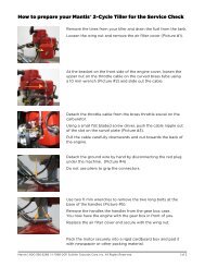
401710 <strong>Tiller</strong> Red 20pgs_???code <strong>Tiller</strong> Grn 5/24/10 11:06 AM Page 15<br />
TROUBLE SHOOTING<br />
Problem Cause Remedy<br />
1. Tines don’t turn when throttle<br />
is depressed<br />
• Engine is not seated properly on the gear<br />
housing.<br />
2. Engine fails to start • o/I switch is in “o” position.<br />
• No fuel in tank.<br />
• Fuel strainer clogged.<br />
• Fuel line clogged.<br />
• Spark plug shorted or fouled.<br />
• Spark plug is broken (cracked<br />
porcelain or electrodes broken)<br />
• Ignition lead wire shorted, broken or<br />
disconnected from spark plug.<br />
• Ignition inoperative<br />
• Re-install engine following the instructions<br />
on page 13 (How to reseat the flange).<br />
• Move switch to “I.”<br />
• Fill Tank.<br />
• Replace Strainer.<br />
• Clean fuel line.<br />
• Install new spark plug.<br />
• Replace spark plug.<br />
• Replace lead wire or attach to spark plug.<br />
• Contact your local authorized dealer.<br />
3. Engine hard to start. • Water in gasoline or stale fuel mixture.<br />
• Too much oil in fuel mixture.<br />
• Engine under or over choked.<br />
• Carburetor out of adjustment.<br />
• Gasket leaks (carburetor or cylinder<br />
base gasket).<br />
• Weak spark at spark plug.<br />
4. Engine continuously floods. • Fuel tank vent line is not in an<br />
upright position.<br />
5. There is black smoke coming from<br />
exhaust<br />
• The muffler screen may be clogged<br />
• The exhaust port may be restricted<br />
6. Engine misses. • Dirt in fuel line or carburetor.<br />
• Carburetor improperly adjusted.<br />
• Spark plug fouled, broken or incorrect<br />
gap setting.<br />
• Weak or intermittent spark at spark plug.<br />
7. Engine lacks power. • Air filter clogged.<br />
• Carburetor out of adjustment.<br />
• Muffler clogged.<br />
• Clogged exhaust ports.<br />
• Spark Arrestor Clogged.<br />
• Poor compression.<br />
8. Engine overheats. • Insufficient oil in fuel mixture<br />
• Air flow obstructed<br />
9. Engine noisy or knocking. • Spark plug in incorrect heat range.<br />
• Bearings, piston ring or cylinder walls<br />
are worn.<br />
10. Engine stalls under load. • Carburetor adjustment too “lean.”<br />
• Engine overheats.<br />
• Drain entire system and refill with<br />
fresh fuel.<br />
• Drain and refill with correct mixture.<br />
• If flooded by over choking, proceed<br />
according to instructions in operation<br />
section. If under choked, move choke<br />
lever to closed position and crank two or<br />
three times.<br />
• See “Carburetor Adjustment.”<br />
• Replace gaskets.<br />
• Contact your local authorized dealer.<br />
• Return the fuel tank vent line to the<br />
upright position and place it under the<br />
cylinder cover in the small “pocket” in<br />
the cylinder cover<br />
• Clean carbon from muffler screen (page 13)<br />
• Clean exhaust port<br />
• Remove and clean.<br />
• See “Carburetor Adjustment.”<br />
• Clean or replace spark plug - set gap to<br />
.024-.028 in. (0.6-0.7 mm)<br />
• Contact your local authorized dealer.<br />
• Clean or replace air filter.<br />
• See “Carburetor Adjustment”.<br />
• Clean carbon from muffler.<br />
• Remove muffler, rotate engine until the<br />
piston is at top of cylinder. With a<br />
wooden scraper or blunt tool, remove all<br />
carbon from exhaust ports. Be careful not<br />
to scratch or damage piston or cylinder<br />
walls. Blow out all loose carbon with<br />
compressed air. Install muffler and gasket.<br />
• Clean Spark Arrestor<br />
• Contact your local authorized dealer.<br />
• Mix fuel as described in starting<br />
instructions.<br />
• Clean flywheel cylinder fins and screen.<br />
• Replace with plugs specified for engine.<br />
• Contact your local authorized dealer.<br />
• See “Carburetor Adjustment.” (page 13)<br />
• Remove dust and dirt from between fins.<br />
15
401710 <strong>Tiller</strong> Red 20pgs_???code <strong>Tiller</strong> Grn 5/24/10 11:06 AM Page 16<br />
MANTIS TILLER ASSEMBLY<br />
ITEM PART # QTY. DESCRIPTION / REMARKS<br />
T36<br />
T23<br />
T25<br />
T8<br />
T24<br />
T21<br />
T14<br />
T12<br />
T9<br />
T3<br />
T10<br />
T17<br />
T38<br />
*T19<br />
T30<br />
T15 T32 T18<br />
T35<br />
T16<br />
T41<br />
T23 T24 T25<br />
T22<br />
T20<br />
T22<br />
T34<br />
T4<br />
T29<br />
T6<br />
T11<br />
T12<br />
#T42<br />
T13<br />
T35<br />
T40<br />
T5<br />
T6<br />
T33<br />
T28<br />
T39<br />
T2<br />
T37<br />
T27<br />
T1<br />
T7<br />
T31<br />
T28<br />
T26<br />
T1 400261 1 Trigger Handle Assm. RH<br />
T2 400263 1 Handle Assm. LH<br />
T3 400224 2 Lower Handle - Fold Down<br />
T4 400620 1 Label<br />
T5 148 1 Handle Brace<br />
T6 478 2 Throttle Clip<br />
T7 465 1 Fender Guard<br />
T8 400904 1 Engine Assm. SV-5CI<br />
* T9 468 1 Drive Shaft<br />
T10 466 1 Worm Gear Housing<br />
T11 436 1 Gasket<br />
T12 437A 1 Housing Cover<br />
T13 651 4 Rd. Hd. Self Tapping Screw<br />
T14 423 1 Roller Bearing<br />
T15 425 2 Worm Bearing Race<br />
T16 424 1 Worm Thrust Bearing<br />
T17 422 1 Worm Shaft<br />
T18 426 1 Worm Disk<br />
T19 428 1 Retaining Ring<br />
T20 429 1 Worm Gear<br />
T21 431 1 Tine Shaft<br />
T22 430 2 Worm Gear Thrust Washer<br />
T23 432 2 Worm Gear Bearing<br />
T24 434 2 Bearing Seal<br />
T25 435 2 Bearing Seal Retainer<br />
T26 438RA 1 Tine Assm. (RT)<br />
T27 438LA 1 Tine Assm. (LT)<br />
T28 418-1 2 Tine Retaining Hair Pin<br />
T29 400133 1 Carrying Handle<br />
T30 487MA 1 Engine Label<br />
T31 4043 1 Tine Label<br />
T32 458 1 Roller Bearing<br />
T33 4058 1 Mantis Label<br />
T34 410 2 Cap Screw 1/4-20 x 1” LG.<br />
T35 972 4 Lock Nut 1/4 - 20<br />
T36 470 2 1/4 - 20 x 3” Bolt<br />
T37 140 2 Bolt 1/4-20 x 3/8” Lg.<br />
T38 377 2 Handle Clamp<br />
T39 400509 2 Bolt<br />
T40 400523 2 Knob<br />
T41 400230 2 Plug<br />
T42 400010 1 Transmission Assm.<br />
* Also in Key #T42<br />
P/N 438LA<br />
P/N 438RA<br />
DIRECTION<br />
DIRECTION<br />
Raised Hub<br />
Raised Hub<br />
Teeth point in<br />
a Clockwise<br />
Direction<br />
When you look at a Tine with the raised hub facing<br />
you and the teeth are pointing in a CLOCKWISE<br />
rotation, you have a LEFT HAND TINE.<br />
16<br />
Teeth point in<br />
a Counter Clock -<br />
wise Direction<br />
When you look at Tine with the raised hub facing you<br />
and the teeth are pointing in a COUNTER CLOCK WISE<br />
rotation, you and a RIGHT HAND TINE.
401710 <strong>Tiller</strong> Red 20pgs_???code <strong>Tiller</strong> Grn 5/24/10 11:06 AM Page 17<br />
SV-5C/2<br />
ENGINE PARTS<br />
ASSEMBLIES<br />
CARBURETOR -- C1U-K82<br />
EXPLOSION A<br />
AIR CLEANER<br />
EXPLOSION B<br />
B2 2<br />
B1 1<br />
B4 4 B6 6<br />
B3 3<br />
8<br />
B7 7<br />
B8<br />
B5 5<br />
A34<br />
A7 7<br />
B10<br />
B9 9<br />
A8 8<br />
B14<br />
B13<br />
A9 9<br />
B12<br />
A12<br />
A11<br />
B11<br />
A19<br />
A1 1<br />
A4 4<br />
A35<br />
A36<br />
A10<br />
B15<br />
A3 3<br />
A6 6<br />
A5 5<br />
B17<br />
B16<br />
A13<br />
A37<br />
A38<br />
A20<br />
A2 2<br />
A24<br />
A25<br />
A22<br />
A26<br />
A27<br />
A28<br />
A29<br />
A30<br />
A17<br />
A16<br />
A15<br />
A31<br />
A14<br />
A32<br />
A33<br />
A18<br />
A21<br />
A23<br />
ITEM PART # QTY. DESCRIPTION / REMARKS<br />
A1 P005000980 4 SCREW, PURGE BASE<br />
A2 P005000620 1 RETAINER, PURGE BULB<br />
A3 12538108660 1 BULB, PURGE<br />
A4 P005000970 1 BASE, PURGE<br />
A5 ------------------- 1 BODY, CARBURETOR / NOT AVAILABLE SEPARATELY<br />
A6 12537613120 1 NOZZLE, CHECK VALVE<br />
A7 12532939030 1 CAP, LIMITER - HIGH SPEED -- RED<br />
A8 12532013310 1 NEEDLE - HIGH SPEED<br />
A9 12532909860 1 CAP, LIMITER - LOW SPEED -- WHITE<br />
A10 12531813120 1 NEEDLE - LOW SPEED<br />
A11 12537242030 1 SWIVEL<br />
A12 P005001070 1 SHAFT, THROTTLE<br />
A13 12532713930 1 CLIP, SWIVEL<br />
A14 12531342030 1 SPRING, THROTTLE RETURN<br />
A15 12531413930 1 SCREW, THROTTLE VALVE<br />
A16 12531649030 1 VALVE, THROTTLE<br />
A17 12532715130 1 CLIP, THROTTLE SHAFT<br />
A18 12532412820 1 COVER, FUEL PUMP<br />
A19 12533406960 1 SCREW, IDLE ADJUST<br />
A20 12533306960 1 SPRING, IDLE ADJUST<br />
A21 12531012820 2 SCREW, FUEL PUMP COVER<br />
A22 12533942030 1 SCREW, METERING LEVER PIN<br />
A23 12530013120 1 REPAIR KIT / INCLUDES ITEMS 24-33<br />
A24 ------------------- 1 DIAPHRAGM, METERING<br />
A25 ------------------- 1 GASKET, METERING DIAPHRAGM<br />
A26 ------------------- 1 PIN, METERING LEVER<br />
A27 ------------------- 1 LEVER, METERING<br />
A28 ------------------- 1 VALVE, INLET NEEDLE<br />
A29 ------------------- 1 WELCH PLUG<br />
A30 ------------------- 1 SPRING, METERING LEVER<br />
A31 ------------------- 1 STRAINER<br />
A32 ------------------- 1 DIAPHRAGM, FUEL PUMP<br />
A33 ------------------- 1 GASKET, FUEL PUMP<br />
A34 12530313120 1 GASKET/DIAPHRAGM KIT / INCLUDES ITEMS 35-38<br />
A35 ------------------- 1 DIAPHRAGM, METERING<br />
A36 ------------------- 1 GASKET, METERING DIAPHRAGM<br />
A37 ------------------- 1 DIAPHRAGM, FUEL PUMP<br />
A38 ------------------- 1 GASKET, FUEL PUMP<br />
ITEM PART # QTY. DESCRIPTION / REMARKS<br />
B1 90052800005 1 WING BOLT<br />
B2 13032611522 1 COVER, AIR CLEANER<br />
B3 89012147530 1 LABEL, CHOKE<br />
B4 13031004560 1 FILTER, AIR<br />
B5 90024205057 2 SCREW 5X57<br />
B6 13041005360 1 PLATE, PREVENT<br />
B7 17851504560 1 SHUTTER, CHOKE<br />
B8 17851600830 1 SPACER<br />
B9 13030104560 1 CASE, AIR CLEANER / INCLUDES ITEM 10<br />
B10 17881005230 1 GROMMET<br />
B11 17851004560 1 ROD, CHOKE<br />
B12 ------------------ 1 CARBURETOR<br />
B13 13001642031 1 GASKET, INTAKE 1<br />
B14 90023805020 2 SCREW 5X20 / SEE CARBURETOR DIAGRAM FOR<br />
ADDITIONAL INFORMATION<br />
B15 90050000005 2 NUT 5<br />
B16 13001742031 1 INSULATOR<br />
B17 V103000490 1 SHIELD, INTAKE 1<br />
1 ALSO INCLUDED IN GASKET KIT (PAGE 19)<br />
MUFFLER<br />
EXPLOSION C<br />
C9 9<br />
C8 8<br />
C4 4<br />
C3 3<br />
C2 2<br />
C6 6<br />
C1 1<br />
C5 5<br />
ITEM PART # QTY. DESCRIPTION / REMARKS<br />
C1 9136704012 3 SCREW 4X12<br />
C2 A313000700 1 GUIDE, EXHAUST<br />
C3 V104000072 1 GASKET, EXHAUST 1<br />
C4 14586240630 1 SCREEN, MUFFLER<br />
C5 90010505055 2 SCREW 5X55<br />
C6 V347000000 4 WASHER, CONICAL<br />
C7 V150000371 1 EYE PLATE<br />
C8 A300000521 1 MUFFLER<br />
C9 V104000590 1 SHIELD, EXHAUST 1<br />
1 ALSO INCLUDED IN GASKET KIT (PAGE 19)<br />
C7 7<br />
17
401710 <strong>Tiller</strong> Red 20pgs_???code <strong>Tiller</strong> Grn 5/24/10 11:06 AM Page 18<br />
SV-5C/2 ENGINE PARTS<br />
ENGINE COVER, FANCASE, STARTER, CLUTCH CASE & CLUTCH<br />
EXPLOSION D<br />
D8<br />
D7<br />
D6<br />
D9<br />
D5<br />
D4<br />
D11<br />
D12<br />
D13<br />
D2<br />
D3<br />
D10<br />
D15<br />
D1<br />
D16<br />
D14<br />
D27<br />
D18<br />
D30<br />
D29<br />
D28<br />
D26<br />
D24<br />
D17<br />
D25<br />
D22<br />
D21<br />
D20<br />
D23<br />
D19<br />
ITEM PART # QTY. DESCRIPTION / REMARKS<br />
D1 A051000950 1 STARTER ASY / INCLUDES ITEMS 2-8<br />
D2 17722042030 1 SPRING, REWIND<br />
D3 17721544430 1 DRUM, STARTER<br />
D4 17723644330 1 SCREW<br />
D5 17722605530 1 ROPE, STARTER - 3X890MM / REPOWER BULK<br />
OPTION: 99944440000<br />
D6 17722742030 1 GUIDE, ROPE<br />
D7 17722811120 1 STARTER GRIP KIT / INCLUDES ITEM 8<br />
D8 17724611120 1 CLIP, STARTER ROPE<br />
D9 90023804016 4 SCREW 4X16<br />
D10 17720212220 1 STARTER PAWL ASY / INCLUDES ITEMS 11-12<br />
D11 17721844330 2 PAWL, STARTER<br />
D12 17723412220 2 SPRING, RETURN<br />
D13 90060500008 1 SPRING WASHER 8<br />
D14 A160000610 1 COVER, ENGINE<br />
D15 90023804018 2 SCREW 4X18<br />
D16 9110704008 1 SCREW 4X8<br />
D17 13041611520 1 BOLT 5X25<br />
D18 90023804018 4 SCREW 4X18<br />
D19 61022311520 1 CASE, CLUTCH<br />
D20 90023806012 1 SCREW 6X12<br />
D21 17501411520 1 WASHER, CLUTCH<br />
D22 17504404630 1 WASHER, CLUTCH<br />
D23 17501004635 1 DRUM, CLUTCH<br />
D24 90080836000 1 BEARING, BALL<br />
D25 90060000010 1 WASHER 10<br />
D26 17501904630 1 PLATE, CLUTCH<br />
D27 17500007531 1 CLUTCH/ASY / INCLUDES ITEMS 12-14<br />
D28 17500905131 2 SHOE, CLUTCH<br />
D29 17501805130 2 SPRING, CLUTCH<br />
D30 17501605020 1 HUB, CLUTCH<br />
IGNITION, ENGINE & SHORT BLOCK<br />
EXPLOSION E<br />
E28<br />
E13<br />
E17<br />
E29<br />
E16<br />
E11<br />
E9 9<br />
E10<br />
E15<br />
E8 8<br />
E18<br />
E19<br />
E26<br />
E25<br />
E23<br />
E24<br />
E6 6<br />
E14<br />
E7 7<br />
E12<br />
E3 3<br />
E5 5<br />
E4 4<br />
E21<br />
E22<br />
E20<br />
ITEM PART # QTY. DESCRIPTION / REMARKS<br />
E2 A130000550 1 CYLINDER<br />
E3 90016205022 2 SCREW 5X22<br />
E4 V100000160 1 GASKET, CYLINDER 1<br />
E5 P021007712 1 PISTON KIT / INCLUDES ITEMS 6-9<br />
E6 A101000090 1 RING, PISTON<br />
E7 10001311520 1 PIN, PISTON<br />
E8 10001504630 2 CIRCLIP, PISTON PIN<br />
E9 10001411520 2 SPACER, PISTON PIN<br />
E10 A011000390 1 CRANKSHAFT ASY / INCLUDES ITEM 11<br />
E11 V553000060 1 BEARING, NEEDLE<br />
E12 10020411521 1 CRANKCASE KIT / INCLUDES ITEMS 13-17<br />
E13 10021242031 2 OIL SEAL<br />
E14 V622000020 2 DOWEL PIN - 4X7.8MM<br />
E15 10024242030 1 GASKET, CRANKCASE 1<br />
E16 9403536201 2 BEARING, BALL - 6201<br />
E17 90016205028 3 SCREW 5X28<br />
E18 9111304020 2 SCREW 4X20<br />
E19 A411000220 1 COIL, IGNITION<br />
E20 16202152830 1 LEAD, IGNITION<br />
E21 15901019830 1 SPARK PLUG -- BPM-8Y<br />
E22 A425000000 1 SPARK PLUG -- BPMR-8Y 2<br />
E23 15901103432 1 TERMINAL, SPARK PLUG<br />
E24 15901201620 1 CAP, SPARK PLUG<br />
E25 15611004920 1 BUSHING<br />
E26 V475002200 1 TUBE, INSULATOR<br />
E27 A409000150 1 FLYWHEEL<br />
E28 61032502730 1 WOODRUFF KEY<br />
1 ALSO INCLUDED IN GASKET KIT (PAGE 19)<br />
2 CANADA MODELS<br />
E13<br />
E2 2<br />
18
401710 <strong>Tiller</strong> Red 20pgs_???code <strong>Tiller</strong> Grn 5/24/10 11:06 AM Page 19<br />
SV-5C/2 ENGINE PARTS<br />
FUEL SYSTEM<br />
EXPLOSION F<br />
GASKET KIT<br />
F13<br />
F12<br />
F14<br />
F1 1 F2 2<br />
F3 3<br />
F15<br />
F4 4<br />
F6 6<br />
F5 5<br />
F9 9<br />
F10<br />
F11<br />
ITEM PART # QTY. DESCRIPTION / REMARKS<br />
F1 90027505015 3 SCREW 5X15<br />
F2 A350000300 1 TANK, FUEL / INCLUDES ITEM 3<br />
F3 13104528230 3 SPACER<br />
F4 V137000030 1 GROMMET<br />
F5 13201309820 1 CLIP<br />
F6 13120507320 1 FILTER, FUEL<br />
F7 V471001230 1 PIPE, FUEL - 3X5X210MM / BULK OPTION: 90014<br />
F8 13201049030 1 PIPE, RETURN - 3X6X50MM / BULK OPTION: 90017<br />
F9 V471001200 1 PIPE, VENT - 3X5X70MM / BULK OPTION: 90014<br />
F10 13011100530 1 CLIP, PIPE<br />
F11 A356000030 1 VENT ASY<br />
F12 13100409060 1 CAP ASY / INCLUDES ITEM 13-14<br />
F13 13101655830 1 GASKET, CAP<br />
F14 13105156030 1 CONNECTOR, CAP<br />
F15 P021009110 1 GASKET KIT<br />
F8 8<br />
F7 7<br />
ECHO INCORPORATED EMISSION CONTROL WARRANTY STATEMENT<br />
FOR ECHO AND SHINDAIWA BRANDS<br />
The Environmental Protection Agency (EPA) and the California Air Resources Board (C.A.R.B.) and ECHO Incorporated<br />
(ECHO Inc.) are pleased to explain the emission control system warranty on your 2010 and later equipment/small off-road<br />
engine (SORE). New equipment/SORE must be designed, built and equipped to meet stringent EPA and C.A.R.B. anti-smog<br />
standards. ECHO Inc. must warrant the emission control system on your equipment/SORE for the periods of time listed below,<br />
provided there has been no abuse, neglect or improper maintenance of your equipment/SORE. Your emission control system<br />
may include parts such as: carburetor, fuel-injection system, ignition system, catalytic converter/muffler, fuel tank, fuel feed<br />
lines, fuel cap assembly, spark plug, air filters, and other associated components. Where a warrantable condition exists, ECHO<br />
Inc will repair your equipment/SORE at no cost to you including diagnosis, parts and labor. The Emission Control System<br />
warranty is extended to the original owner including all subsequent owners.<br />
MANUFACTURER’S WARRANTY COVERAGE:<br />
The emission control system is warranted for 2 years or the length of the ECHO Inc. warranty, whichever is longer. If any<br />
emission-related part on your equipment is defective, the part will be repaired or replaced by ECHO Inc. or its Authorized<br />
Service Representative.<br />
OWNER’S WARRANTY RESPONSIBILITIES:<br />
As the equipment/SORE owner, you are responsible for the performance of the required maintenance listed in your Operator's<br />
Manual. ECHO Inc. recommends that you retain all receipts covering maintenance on your equipment/SORE however, ECHO<br />
Inc. cannot deny warranty solely for the lack of receipts or for your failure to ensure the performance of all scheduled<br />
maintenance. As the equipment/SORE owner, you should be aware that ECHO Inc. may deny you warranty coverage if your<br />
equipment/SORE or a part has failed due to abuse, neglect, improper maintenance or unapproved modifications.<br />
You are responsible for presenting your equipment/SORE to an ECHO Inc. authorized service representative as soon as a<br />
problem exists. The warranty repairs should be completed in a reasonable amount of time, not to exceed 30 days. If a<br />
warrantable condition exists and there is no Authorized Dealer within 100 miles, ECHO Inc. will pay to ship the unit to the<br />
nearest authorized dealer. If you have questions regarding your warranty coverage, you should contact ECHO Inc. at 1-800-673-<br />
1558, web site WWW.ECHO-USA.COM or contact Shindaiwa at 1-877-986-7783, web site WWW.SHINDAIWA.COM.<br />
WHAT DOES THIS WARRANTY COVER?<br />
ECHO Inc. warrants that your equipment/SORE was designed, built and equipped to conform with applicable EPA and C.A.R.B.<br />
emissions standards and that your equipment/SORE is free from defects in material and workmanship that would cause it to fail<br />
to conform with applicable requirements for 2 years or the length of the ECHO Inc. warranty, whichever is longer. The warranty<br />
period begins on the date the product is purchased by an end user..<br />
HOW WILL A COVERED PART BE CORRECTED?<br />
If there is a defect in a part covered by this warranty, any ECHO Inc. Authorized Service Dealer will correct the defect. You will<br />
not have to pay anything to have the part adjusted, repaired or replaced. This includes any labor and diagnosis for warranted<br />
repairs performed by the dealer. In addition, engine parts not expressly covered under this warranty but whose failure is a result<br />
of a failure of a covered part will be warranted.<br />
WHAT PARTS ARE COVERED?<br />
• Any applicable emission related part not scheduled for "required maintenance" will be repaired or replaced within the<br />
warranty period. The repaired or replaced part will be warranted for the remaining ECHO Inc. warranty period. Continued ➠<br />
19
401710 <strong>Tiller</strong> Red 20pgs_???code <strong>Tiller</strong> Grn 5/24/10 11:06 AM Page 20<br />
• Any warranted part that is scheduled only for regular inspection in the written instructions supplied is warranted for the<br />
warranty period stated above. Any such part repaired or replaced under warranty will be warranted for the remaining ECHO<br />
Inc. warranty period.<br />
• Any emission related part scheduled for replacement during "required maintenance" is warranted for the period of time prior<br />
to the first scheduled replacement point for that part. Any such part repaired or replaced under warranty shall be warranted<br />
for the remainder of the period prior to the first scheduled replacement point for that part.<br />
• Any manufacturer-approved replacement part may be used in the performance of any warranty maintenance or repairs on<br />
emission related parts, and must be provided without charge if the part is still under warranty.<br />
• Any replacement part that is equivalent in performance and durability may be used in non-warranty maintenance or repairs,<br />
and shall not reduce the warranty obligations of the manufacturer.<br />
• Throughout the equipment/SORE warranty period, ECHO Inc. will maintain a supply of warranted parts sufficient to meet the<br />
expected demand for such parts.<br />
SPECIFIC EMISSION RELATED WARRANTED PARTS:<br />
• Electronic Ignition System<br />
• Spark Plug<br />
• Catalytic Converter / Muffler Assembly<br />
• Carburetor (complete assembly or replaceable components)<br />
• Choke<br />
• Fuel-Injection Assembly (or replaceable components)<br />
• Fuel Tank<br />
• Fuel Cap Assembly<br />
• Air Filter<br />
• Fuel Feed Line (and associated clamps/connectors as applicable)<br />
WHAT IS NOT COVERED?<br />
Any failure caused by abuse, neglect, improper maintenance, unapproved modifications, use of unapproved add-on<br />
parts/modified parts or unapproved accessories.<br />
This Emission Control Warranty is valid only for the U.S.A., it's Territories, and Canada. 99922201033 01/2010<br />
MANTIS TILLER LIMITED WARRANTY<br />
MANTIS extends this limited warranty against defects in<br />
material and workmanship for a period of five (5) years for<br />
normal residential purposes and two (2) years for commercial<br />
use from the date of purchase, to the first retail purchaser and<br />
each subsequent owner, during the warranty period. This<br />
warranty covers all portions of the MANTIS TILLER.<br />
MANTIS will repair or replace, at its option, any part or parts of<br />
the product proven to be defective in material or workmanship<br />
under normal usage during the warranty period. Warranty<br />
repairs and replacements will be made without charge for parts<br />
or labor. All parts replaced under warranty will be considered<br />
as part of the original product, and any warranty on the<br />
replaced parts will expire coincident with the original product<br />
warranty. If you think your MANTIS TILLER is defective in<br />
material or workmanship, you must send it, along with your<br />
proof of purchase (sales receipt) to:<br />
Mantis<br />
1028 Street Road<br />
Southampton, PA 18966<br />
You are responsible for pickup and delivery charges; the<br />
product must be returned to us postage paid.<br />
MANTIS assumes no responsibility in the event that the<br />
product was not assembled or used in compliance with any<br />
assembly, care, safety, or operating instructions contained in the<br />
Owner’s Manual or accompanying the product; was not used<br />
with reasonable care or requires replacement or repair due to<br />
accidents or lack of proper maintenance; or was misused,<br />
altered, used for other than normal or intended purposes. This<br />
warranty does not cover damage due to normal wear and tear.<br />
You must maintain your MANTIS TILLER by following the<br />
maintenance procedures described in the owner’s manual. Such<br />
routine maintenance, whether performed by you or a dealer, is<br />
at your expense.<br />
MANTIS MAKES NO EXPRESS OR IMPLIED WARRANTIES<br />
OR REPRESENTATIONS EXCEPT THOSE CONTAINED<br />
HEREIN. THE DURATION OF ANY IMPLIED WARRANTY,<br />
INCLUDING MERCHANTABILITY AND FITNESS FOR A<br />
PARTICULAR PURPOSE, IS LIMITED TO THE DURATION OF<br />
THIS WRITTEN LIMITED WARRANTY. MANTIS DISCLAIMS<br />
ALL LIABILITY FOR INDIRECT, INCIDENTAL AND/OR<br />
CONSEQUENTIAL DAMAGES IN CONNECTION WITH THE<br />
USE OF THE MANTIS PRODUCTS COVERED BY THIS<br />
WARRANTY. SOME STATES DO NOT ALLOW LIMITATIONS<br />
ON HOW LONG AN IMPLIED WARRANTY LASTS AND/OR<br />
DO NOT ALLOW THE EXCLUSION OR LIMITATION OF<br />
INCIDENTAL OR CONSEQUENTIAL DAMAGES, SO THAT<br />
ABOVE LIMITATIONS AND EXCLUSIONS MAY NOT APPLY<br />
TO YOU. THIS WARRANTY GIVES YOU SPECIFIC LEGAL<br />
RIGHTS, AND YOU MAY ALSO HAVE OTHER RIGHTS<br />
WHICH VARY FROM STATES TO STATE.<br />
MANTIS<br />
1028 Street Road<br />
Southampton, PA 18966<br />
(215) 355-9700<br />
Specifications, descriptions, and illustrative material in this literature are as accurate as known at the time of publication, but are subject to change without notice.<br />
P/N 401710 3/10<br />
© 2010 Schiller Grounds Care, Inc. All rights reserved.<br />
Printed in USA