Liebert Mini-Mate2, 8 Ton - Emerson Network Power
Liebert Mini-Mate2, 8 Ton - Emerson Network Power
Liebert Mini-Mate2, 8 Ton - Emerson Network Power

Create successful ePaper yourself
Turn your PDF publications into a flip-book with our unique Google optimized e-Paper software.
<strong>Liebert</strong> <strong>Mini</strong>-<strong>Mate2</strong> <br />
User Manual - 8 <strong>Ton</strong>s, 50 & 60Hz<br />
Precision Cooling<br />
For Business-Critical Continuity
TABLE OF CONTENTS<br />
MODEL NUMBER NOMENCLATURE . . . . . . . . . . . . . . . . . . . . . . . . . . . . . . . . . . . . . . . . . . . . . . . . . V<br />
1.0 PRODUCT FEATURES . . . . . . . . . . . . . . . . . . . . . . . . . . . . . . . . . . . . . . . . . . . . . . . . . . . . .1<br />
1.1 Standard Product Features . . . . . . . . . . . . . . . . . . . . . . . . . . . . . . . . . . . . . . . . . . . . . . . . . . . . 1<br />
1.1.1 Controls . . . . . . . . . . . . . . . . . . . . . . . . . . . . . . . . . . . . . . . . . . . . . . . . . . . . . . . . . . . . . . . . . . . . . 1<br />
1.1.2 Evaporator System Components . . . . . . . . . . . . . . . . . . . . . . . . . . . . . . . . . . . . . . . . . . . . . . . . . 1<br />
1.1.3 Condensing Unit Components . . . . . . . . . . . . . . . . . . . . . . . . . . . . . . . . . . . . . . . . . . . . . . . . . . . 1<br />
1.2 Optional Equipment. . . . . . . . . . . . . . . . . . . . . . . . . . . . . . . . . . . . . . . . . . . . . . . . . . . . . . . . . . 2<br />
1.2.1 Canister Humidifier . . . . . . . . . . . . . . . . . . . . . . . . . . . . . . . . . . . . . . . . . . . . . . . . . . . . . . . . . . . 2<br />
1.2.2 Electric Reheat . . . . . . . . . . . . . . . . . . . . . . . . . . . . . . . . . . . . . . . . . . . . . . . . . . . . . . . . . . . . . . . 2<br />
1.2.3 SCR Electric Reheat . . . . . . . . . . . . . . . . . . . . . . . . . . . . . . . . . . . . . . . . . . . . . . . . . . . . . . . . . . . 2<br />
1.2.4 Hot Gas Bypass (Condensing Units) . . . . . . . . . . . . . . . . . . . . . . . . . . . . . . . . . . . . . . . . . . . . . . 2<br />
1.2.5 Free-Cooling Coil (GLYCOOL) . . . . . . . . . . . . . . . . . . . . . . . . . . . . . . . . . . . . . . . . . . . . . . . . . . 2<br />
1.2.6 Smoke Detector. . . . . . . . . . . . . . . . . . . . . . . . . . . . . . . . . . . . . . . . . . . . . . . . . . . . . . . . . . . . . . . 2<br />
1.2.7 Firestat . . . . . . . . . . . . . . . . . . . . . . . . . . . . . . . . . . . . . . . . . . . . . . . . . . . . . . . . . . . . . . . . . . . . . 2<br />
1.2.8 Filter Clog . . . . . . . . . . . . . . . . . . . . . . . . . . . . . . . . . . . . . . . . . . . . . . . . . . . . . . . . . . . . . . . . . . . 2<br />
1.3 Ancillary (Ship Loose Accessories) . . . . . . . . . . . . . . . . . . . . . . . . . . . . . . . . . . . . . . . . . . . . . . 3<br />
1.3.1 Single Point <strong>Power</strong> Kit . . . . . . . . . . . . . . . . . . . . . . . . . . . . . . . . . . . . . . . . . . . . . . . . . . . . . . . . . 3<br />
1.3.2 Refrigerant Line Sweat Adapter Kits . . . . . . . . . . . . . . . . . . . . . . . . . . . . . . . . . . . . . . . . . . . . . 3<br />
1.3.3 Return Air Filter Box with Duct Collar Kit . . . . . . . . . . . . . . . . . . . . . . . . . . . . . . . . . . . . . . . . 3<br />
1.3.4 Condensate Pump Kit . . . . . . . . . . . . . . . . . . . . . . . . . . . . . . . . . . . . . . . . . . . . . . . . . . . . . . . . . 3<br />
1.3.5 Remote Monitoring and Control . . . . . . . . . . . . . . . . . . . . . . . . . . . . . . . . . . . . . . . . . . . . . . . . . 3<br />
1.3.6 Remote Sensors. . . . . . . . . . . . . . . . . . . . . . . . . . . . . . . . . . . . . . . . . . . . . . . . . . . . . . . . . . . . . . . 3<br />
2.0 SITE PREPARATION AND INSTALLATION. . . . . . . . . . . . . . . . . . . . . . . . . . . . . . . . . . . . . . . .4<br />
2.1 Installation Considerations . . . . . . . . . . . . . . . . . . . . . . . . . . . . . . . . . . . . . . . . . . . . . . . . . . . . 4<br />
2.1.1 Room Preparation. . . . . . . . . . . . . . . . . . . . . . . . . . . . . . . . . . . . . . . . . . . . . . . . . . . . . . . . . . . . . 4<br />
2.1.2 Location Considerations. . . . . . . . . . . . . . . . . . . . . . . . . . . . . . . . . . . . . . . . . . . . . . . . . . . . . . . . 5<br />
2.2 System Weights . . . . . . . . . . . . . . . . . . . . . . . . . . . . . . . . . . . . . . . . . . . . . . . . . . . . . . . . . . . . . 7<br />
2.3 Equipment Inspection upon receipt . . . . . . . . . . . . . . . . . . . . . . . . . . . . . . . . . . . . . . . . . . . . . 7<br />
2.4 Installing the Evaporator or Chilled-Water Units . . . . . . . . . . . . . . . . . . . . . . . . . . . . . . . . . . 8<br />
2.4.1 Close Coupled Installations . . . . . . . . . . . . . . . . . . . . . . . . . . . . . . . . . . . . . . . . . . . . . . . . . . . . . 9<br />
2.4.2 Evaporator Air Distribution. . . . . . . . . . . . . . . . . . . . . . . . . . . . . . . . . . . . . . . . . . . . . . . . . . . . 10<br />
2.4.3 Piping Connections and Coolant Requirements . . . . . . . . . . . . . . . . . . . . . . . . . . . . . . . . . . . . 11<br />
2.4.4 Electrical Connections, Evaporator or Chilled-Water Unit . . . . . . . . . . . . . . . . . . . . . . . . . . 17<br />
2.5 Indoor Air-Cooled Centrifugal Fan Condensing Unit Installation . . . . . . . . . . . . . . . . . . . . 19<br />
2.5.1 Location Considerations. . . . . . . . . . . . . . . . . . . . . . . . . . . . . . . . . . . . . . . . . . . . . . . . . . . . . . . 19<br />
2.5.2 Ducting . . . . . . . . . . . . . . . . . . . . . . . . . . . . . . . . . . . . . . . . . . . . . . . . . . . . . . . . . . . . . . . . . . . . 19<br />
2.5.3 Piping Connections. . . . . . . . . . . . . . . . . . . . . . . . . . . . . . . . . . . . . . . . . . . . . . . . . . . . . . . . . . . 20<br />
2.5.4 Electrical Connections - Condensing Unit . . . . . . . . . . . . . . . . . . . . . . . . . . . . . . . . . . . . . . . . 20<br />
2.6 Outdoor Air-Cooled Condensing Unit Installation. . . . . . . . . . . . . . . . . . . . . . . . . . . . . . . . . 23<br />
2.6.1 Location Considerations. . . . . . . . . . . . . . . . . . . . . . . . . . . . . . . . . . . . . . . . . . . . . . . . . . . . . . . 23<br />
2.6.2 Piping Connections. . . . . . . . . . . . . . . . . . . . . . . . . . . . . . . . . . . . . . . . . . . . . . . . . . . . . . . . . . . 23<br />
2.6.3 Electrical Connections . . . . . . . . . . . . . . . . . . . . . . . . . . . . . . . . . . . . . . . . . . . . . . . . . . . . . . . . 23<br />
i
2.7 Indoor Water- and Glycol-Cooled Condensing Unit Installation. . . . . . . . . . . . . . . . . . . . . . 27<br />
2.7.1 Location Considerations. . . . . . . . . . . . . . . . . . . . . . . . . . . . . . . . . . . . . . . . . . . . . . . . . . . . . . . 27<br />
2.7.2 Piping Connections. . . . . . . . . . . . . . . . . . . . . . . . . . . . . . . . . . . . . . . . . . . . . . . . . . . . . . . . . . . 27<br />
2.7.3 Electrical Connections . . . . . . . . . . . . . . . . . . . . . . . . . . . . . . . . . . . . . . . . . . . . . . . . . . . . . . . . 27<br />
2.8 Optional Equipment Piping . . . . . . . . . . . . . . . . . . . . . . . . . . . . . . . . . . . . . . . . . . . . . . . . . . . 31<br />
2.8.1 Free-Cooling Coil (GLYCOOL) . . . . . . . . . . . . . . . . . . . . . . . . . . . . . . . . . . . . . . . . . . . . . . . . . 31<br />
2.9 Checklist for Completed Installation . . . . . . . . . . . . . . . . . . . . . . . . . . . . . . . . . . . . . . . . . . . 33<br />
3.0 MICROPROCESSOR CONTROL . . . . . . . . . . . . . . . . . . . . . . . . . . . . . . . . . . . . . . . . . . . . . .34<br />
3.1 Feature Overview . . . . . . . . . . . . . . . . . . . . . . . . . . . . . . . . . . . . . . . . . . . . . . . . . . . . . . . . . . . 34<br />
3.2 Main Menu . . . . . . . . . . . . . . . . . . . . . . . . . . . . . . . . . . . . . . . . . . . . . . . . . . . . . . . . . 35<br />
3.3 Setpoints . . . . . . . . . . . . . . . . . . . . . . . . . . . . . . . . . . . . . . . . . . . . . . . . . . . . . . . . . . . . . . . . . . 36<br />
3.4 Status . . . . . . . . . . . . . . . . . . . . . . . . . . . . . . . . . . . . . . . . . . . . . . . . . . . . . . . . . . . . . . . . . . . . 36<br />
3.5 Active Alarms . . . . . . . . . . . . . . . . . . . . . . . . . . . . . . . . . . . . . . . . . . . . . . . . . . . . . . . . . . . . . . 36<br />
3.6 Alarm History . . . . . . . . . . . . . . . . . . . . . . . . . . . . . . . . . . . . . . . . . . . . . . . . . . . . . . . . . . . . . . 36<br />
3.7 Time. . . . . . . . . . . . . . . . . . . . . . . . . . . . . . . . . . . . . . . . . . . . . . . . . . . . . . . . . . . . . . . . . . . . . . 37<br />
3.8 Date . . . . . . . . . . . . . . . . . . . . . . . . . . . . . . . . . . . . . . . . . . . . . . . . . . . . . . . . . . . . . . . . . . . . . . 37<br />
3.9 Setback . . . . . . . . . . . . . . . . . . . . . . . . . . . . . . . . . . . . . . . . . . . . . . . . . . . . . . . . . . . . . . . . . . . 37<br />
3.10 Setup Operation . . . . . . . . . . . . . . . . . . . . . . . . . . . . . . . . . . . . . . . . . . . . . . . . . . . . . . . . . . . . 37<br />
3.10.1 Restart Time Delay. . . . . . . . . . . . . . . . . . . . . . . . . . . . . . . . . . . . . . . . . . . . . . . . . . . . . . . . . . . 37<br />
3.10.2 C/F Degrees. . . . . . . . . . . . . . . . . . . . . . . . . . . . . . . . . . . . . . . . . . . . . . . . . . . . . . . . . . . . . . . . . 38<br />
3.10.3 Humidity Control Method . . . . . . . . . . . . . . . . . . . . . . . . . . . . . . . . . . . . . . . . . . . . . . . . . . . . . 38<br />
3.10.4 Lead Compressor . . . . . . . . . . . . . . . . . . . . . . . . . . . . . . . . . . . . . . . . . . . . . . . . . . . . . . . . . . . . 38<br />
3.10.5 Show DIP Switch . . . . . . . . . . . . . . . . . . . . . . . . . . . . . . . . . . . . . . . . . . . . . . . . . . . . . . . . . . . . 38<br />
3.10.6 Valve Time (For Systems With a Modulating Chilled-Water Valve) . . . . . . . . . . . . . . . . . . . 38<br />
3.10.7 CW Flush (For Systems With a Modulating Chilled-Water Valve). . . . . . . . . . . . . . . . . . . . . 39<br />
3.11 Change Passwords . . . . . . . . . . . . . . . . . . . . . . . . . . . . . . . . . . . . . . . . . . . . . . . . . . . . . . . . . . 39<br />
3.12 Calibrate Sensors . . . . . . . . . . . . . . . . . . . . . . . . . . . . . . . . . . . . . . . . . . . . . . . . . . . . . . . . . . . 39<br />
3.13 Alarm Enable . . . . . . . . . . . . . . . . . . . . . . . . . . . . . . . . . . . . . . . . . . . . . . . . . . . . . . . . . . . . . . 39<br />
3.14 Alarm Time Delay . . . . . . . . . . . . . . . . . . . . . . . . . . . . . . . . . . . . . . . . . . . . . . . . . . . . . . . . . . 40<br />
3.15 Common Alarm Enable . . . . . . . . . . . . . . . . . . . . . . . . . . . . . . . . . . . . . . . . . . . . . . . . . . . . . . 40<br />
3.16 Custom Alarms . . . . . . . . . . . . . . . . . . . . . . . . . . . . . . . . . . . . . . . . . . . . . . . . . . . . . . . . . . . . . 40<br />
3.17 Custom Text . . . . . . . . . . . . . . . . . . . . . . . . . . . . . . . . . . . . . . . . . . . . . . . . . . . . . . . . . . . . . . . 41<br />
3.18 Run Diagnostics . . . . . . . . . . . . . . . . . . . . . . . . . . . . . . . . . . . . . . . . . . . . . . . . . . . . . . . . . . . . 42<br />
4.0 SYSTEM PERFORMANCE MICROPROCESSOR CONTROLS . . . . . . . . . . . . . . . . . . . . . . . . . .45<br />
4.1 Control Type Response Proportional Control . . . . . . . . . . . . . . . . . . . . . . . . . . . . . . . . . . . . . 45<br />
4.2 Cooling . . . . . . . . . . . . . . . . . . . . . . . . . . . . . . . . . . . . . . . . . . . . . . . . . . . . . . . . . . . . . . . . . . . 45<br />
4.2.1 Multi-Step Cooling, Compressorized Direct Expansion (DX) Systems . . . . . . . . . . . . . . . . . . 45<br />
4.2.2 Chilled-Water Cooling (8 <strong>Ton</strong>) . . . . . . . . . . . . . . . . . . . . . . . . . . . . . . . . . . . . . . . . . . . . . . . . . . 45<br />
4.2.3 GLYCOOL Cooling (8 <strong>Ton</strong>) . . . . . . . . . . . . . . . . . . . . . . . . . . . . . . . . . . . . . . . . . . . . . . . . . . . . 45<br />
ii
4.3 Reheat . . . . . . . . . . . . . . . . . . . . . . . . . . . . . . . . . . . . . . . . . . . . . . . . . . . . . . . . . . . . . . . . . . . . 45<br />
4.3.1 Electric Reheat - Staged. . . . . . . . . . . . . . . . . . . . . . . . . . . . . . . . . . . . . . . . . . . . . . . . . . . . . . . 45<br />
4.3.2 SCR Electric Reheat . . . . . . . . . . . . . . . . . . . . . . . . . . . . . . . . . . . . . . . . . . . . . . . . . . . . . . . . . . 45<br />
4.4 Dehumidification / Humidification Percent Required . . . . . . . . . . . . . . . . . . . . . . . . . . . . . . 46<br />
4.4.1 Staged Dehumidification, Compressorized Direct Expansion (DX) Systems . . . . . . . . . . . . . 46<br />
4.4.2 Humidification Operation . . . . . . . . . . . . . . . . . . . . . . . . . . . . . . . . . . . . . . . . . . . . . . . . . . . . . 46<br />
4.4.3 Dehumidification Lockout . . . . . . . . . . . . . . . . . . . . . . . . . . . . . . . . . . . . . . . . . . . . . . . . . . . . . 46<br />
4.5 Load Control Features . . . . . . . . . . . . . . . . . . . . . . . . . . . . . . . . . . . . . . . . . . . . . . . . . . . . . . . 46<br />
4.6 Communications. . . . . . . . . . . . . . . . . . . . . . . . . . . . . . . . . . . . . . . . . . . . . . . . . . . . . . . . . . . . 46<br />
5.0 ALARMS. . . . . . . . . . . . . . . . . . . . . . . . . . . . . . . . . . . . . . . . . . . . . . . . . . . . . . . . . . . . . .47<br />
5.1 Alarms: Definitions and Troubleshooting . . . . . . . . . . . . . . . . . . . . . . . . . . . . . . . . . . . . . . . . 47<br />
5.1.1 Custom Alarms . . . . . . . . . . . . . . . . . . . . . . . . . . . . . . . . . . . . . . . . . . . . . . . . . . . . . . . . . . . . . . 47<br />
5.1.2 High Head Pressure . . . . . . . . . . . . . . . . . . . . . . . . . . . . . . . . . . . . . . . . . . . . . . . . . . . . . . . . . . 47<br />
5.1.3 Humidity . . . . . . . . . . . . . . . . . . . . . . . . . . . . . . . . . . . . . . . . . . . . . . . . . . . . . . . . . . . . . . . . . . . 48<br />
5.1.4 Temperature . . . . . . . . . . . . . . . . . . . . . . . . . . . . . . . . . . . . . . . . . . . . . . . . . . . . . . . . . . . . . . . . 48<br />
5.1.5 Humidifier Problem Alarm . . . . . . . . . . . . . . . . . . . . . . . . . . . . . . . . . . . . . . . . . . . . . . . . . . . . 48<br />
5.1.6 High-Water Alarm . . . . . . . . . . . . . . . . . . . . . . . . . . . . . . . . . . . . . . . . . . . . . . . . . . . . . . . . . . . 48<br />
5.1.7 Loss of <strong>Power</strong> . . . . . . . . . . . . . . . . . . . . . . . . . . . . . . . . . . . . . . . . . . . . . . . . . . . . . . . . . . . . . . . 48<br />
5.1.8 Short Cycle . . . . . . . . . . . . . . . . . . . . . . . . . . . . . . . . . . . . . . . . . . . . . . . . . . . . . . . . . . . . . . . . . 48<br />
5.2 Optional/Custom Alarms . . . . . . . . . . . . . . . . . . . . . . . . . . . . . . . . . . . . . . . . . . . . . . . . . . . . . 49<br />
5.2.1 Change Filter . . . . . . . . . . . . . . . . . . . . . . . . . . . . . . . . . . . . . . . . . . . . . . . . . . . . . . . . . . . . . . . 49<br />
5.2.2 Firestat . . . . . . . . . . . . . . . . . . . . . . . . . . . . . . . . . . . . . . . . . . . . . . . . . . . . . . . . . . . . . . . . . . . . 49<br />
5.2.3 Smoke Detector. . . . . . . . . . . . . . . . . . . . . . . . . . . . . . . . . . . . . . . . . . . . . . . . . . . . . . . . . . . . . . 49<br />
6.0 SYSTEM OPERATION, TESTING, AND MAINTENANCE. . . . . . . . . . . . . . . . . . . . . . . . . . . . . .50<br />
6.1 System Testing . . . . . . . . . . . . . . . . . . . . . . . . . . . . . . . . . . . . . . . . . . . . . . . . . . . . . . . . . . . . . 50<br />
6.1.1 Environmental Control Functions. . . . . . . . . . . . . . . . . . . . . . . . . . . . . . . . . . . . . . . . . . . . . . . 50<br />
6.1.2 Cooling. . . . . . . . . . . . . . . . . . . . . . . . . . . . . . . . . . . . . . . . . . . . . . . . . . . . . . . . . . . . . . . . . . . . . 50<br />
6.1.3 Heating . . . . . . . . . . . . . . . . . . . . . . . . . . . . . . . . . . . . . . . . . . . . . . . . . . . . . . . . . . . . . . . . . . . . 50<br />
6.1.4 Humidification . . . . . . . . . . . . . . . . . . . . . . . . . . . . . . . . . . . . . . . . . . . . . . . . . . . . . . . . . . . . . . 50<br />
6.1.5 Dehumidification . . . . . . . . . . . . . . . . . . . . . . . . . . . . . . . . . . . . . . . . . . . . . . . . . . . . . . . . . . . . 50<br />
6.1.6 Remote Shutdown. . . . . . . . . . . . . . . . . . . . . . . . . . . . . . . . . . . . . . . . . . . . . . . . . . . . . . . . . . . . 50<br />
6.2 Maintenance and Component Operation . . . . . . . . . . . . . . . . . . . . . . . . . . . . . . . . . . . . . . . . 51<br />
6.2.1 Electric Panel . . . . . . . . . . . . . . . . . . . . . . . . . . . . . . . . . . . . . . . . . . . . . . . . . . . . . . . . . . . . . . . 51<br />
6.2.2 Filters . . . . . . . . . . . . . . . . . . . . . . . . . . . . . . . . . . . . . . . . . . . . . . . . . . . . . . . . . . . . . . . . . . . . . 51<br />
6.2.3 Blower System . . . . . . . . . . . . . . . . . . . . . . . . . . . . . . . . . . . . . . . . . . . . . . . . . . . . . . . . . . . . . . 51<br />
6.2.4 Electric Reheat . . . . . . . . . . . . . . . . . . . . . . . . . . . . . . . . . . . . . . . . . . . . . . . . . . . . . . . . . . . . . . 52<br />
6.2.5 Refrigeration System . . . . . . . . . . . . . . . . . . . . . . . . . . . . . . . . . . . . . . . . . . . . . . . . . . . . . . . . . 52<br />
6.2.6 Steam Generating Humidifier - Operation Procedures . . . . . . . . . . . . . . . . . . . . . . . . . . . . . . 55<br />
6.2.7 Circuit Board Adjustments . . . . . . . . . . . . . . . . . . . . . . . . . . . . . . . . . . . . . . . . . . . . . . . . . . . . 56<br />
7.0 MAINTENANCE INSPECTION CHECKLIST. . . . . . . . . . . . . . . . . . . . . . . . . . . . . . . . . . . . . . .57<br />
8.0 TROUBLESHOOTING . . . . . . . . . . . . . . . . . . . . . . . . . . . . . . . . . . . . . . . . . . . . . . . . . . . . .58<br />
iii
FIGURES<br />
Figure 1 System configurations—air cooled systems. . . . . . . . . . . . . . . . . . . . . . . . . . . . . . . . . . . . . . . . . . . . 6<br />
Figure 2 System Configurations—water/glycol systems . . . . . . . . . . . . . . . . . . . . . . . . . . . . . . . . . . . . . . . . . 6<br />
Figure 3 System Configurations—chilled water systems . . . . . . . . . . . . . . . . . . . . . . . . . . . . . . . . . . . . . . . . 7<br />
Figure 4 Threaded rod and hardware kit installation . . . . . . . . . . . . . . . . . . . . . . . . . . . . . . . . . . . . . . . . . . . 8<br />
Figure 5 Close coupled installation. . . . . . . . . . . . . . . . . . . . . . . . . . . . . . . . . . . . . . . . . . . . . . . . . . . . . . . . . . 9<br />
Figure 6 Drain installation . . . . . . . . . . . . . . . . . . . . . . . . . . . . . . . . . . . . . . . . . . . . . . . . . . . . . . . . . . . . . . . 11<br />
Figure 7 Condensate pump installation . . . . . . . . . . . . . . . . . . . . . . . . . . . . . . . . . . . . . . . . . . . . . . . . . . . . . 12<br />
Figure 8 General arrangement diagram - chilled-water systems . . . . . . . . . . . . . . . . . . . . . . . . . . . . . . . . . 13<br />
Figure 9 Refrigerant piping diagram . . . . . . . . . . . . . . . . . . . . . . . . . . . . . . . . . . . . . . . . . . . . . . . . . . . . . . . 14<br />
Figure 10 Evaporator or chilled-water unit dimensional data . . . . . . . . . . . . . . . . . . . . . . . . . . . . . . . . . . . . 16<br />
Figure 11 Evaporator unit electrical connections . . . . . . . . . . . . . . . . . . . . . . . . . . . . . . . . . . . . . . . . . . . . . . 18<br />
Figure 12 Piping connections - indoor air-cooled centrifugal fan condensing unit . . . . . . . . . . . . . . . . . . . . 20<br />
Figure 13 Indoor air-cooled centrifugal condensing unit dimensions and pipe connections . . . . . . . . . . . . . 21<br />
Figure 14 Indoor air-cooled centrifugal condenser electrical connections . . . . . . . . . . . . . . . . . . . . . . . . . . . 22<br />
Figure 15 Electrical field connections - outdoor condensing unit . . . . . . . . . . . . . . . . . . . . . . . . . . . . . . . . . . 24<br />
Figure 16 Footprint dimensions - outdoor condensing unit. . . . . . . . . . . . . . . . . . . . . . . . . . . . . . . . . . . . . . . 25<br />
Figure 17 Piping and electrical connections - outdoor condensing unit . . . . . . . . . . . . . . . . . . . . . . . . . . . . . 26<br />
Figure 18 Indoor water/glycol condensing unit dimensional data . . . . . . . . . . . . . . . . . . . . . . . . . . . . . . . . . 28<br />
Figure 19 Indoor water/glycol condensing unit electrical field connections . . . . . . . . . . . . . . . . . . . . . . . . . . 29<br />
Figure 20 System piping with indoor water/glycol-cooled condensing unit . . . . . . . . . . . . . . . . . . . . . . . . . . 30<br />
Figure 21 Optional free cooling coil (3-way valve) on water/glycol units . . . . . . . . . . . . . . . . . . . . . . . . . . . . 31<br />
Figure 22 Optional free cooling coil (3-way valve) on air-cooled units . . . . . . . . . . . . . . . . . . . . . . . . . . . . . . 32<br />
Figure 23 Wall box . . . . . . . . . . . . . . . . . . . . . . . . . . . . . . . . . . . . . . . . . . . . . . . . . . . . . . . . . . . . . . . . . . . . . . . 34<br />
Figure 24 Control menu. . . . . . . . . . . . . . . . . . . . . . . . . . . . . . . . . . . . . . . . . . . . . . . . . . . . . . . . . . . . . . . . . . . 43<br />
Figure 25 Control board (inside evaporator) . . . . . . . . . . . . . . . . . . . . . . . . . . . . . . . . . . . . . . . . . . . . . . . . . . 44<br />
Figure 26 Wall box board. . . . . . . . . . . . . . . . . . . . . . . . . . . . . . . . . . . . . . . . . . . . . . . . . . . . . . . . . . . . . . . . . . 44<br />
TABLES<br />
Table i Heat rejection matchup – 60 Hz. . . . . . . . . . . . . . . . . . . . . . . . . . . . . . . . . . . . . . . . . . . . . . . . . . . . . v<br />
Table ii Heat rejection matchup – 50 Hz. . . . . . . . . . . . . . . . . . . . . . . . . . . . . . . . . . . . . . . . . . . . . . . . . . . . . v<br />
Table 1 Application limits, evaporator and chilled-water units* . . . . . . . . . . . . . . . . . . . . . . . . . . . . . . . . . 4<br />
Table 2 Application limits, indoor and outdoor air-cooled condensing units . . . . . . . . . . . . . . . . . . . . . . . . 4<br />
Table 3 Application limits, indoor water/glycol-cooled condensing units . . . . . . . . . . . . . . . . . . . . . . . . . . . 4<br />
Table 4 Unit weights . . . . . . . . . . . . . . . . . . . . . . . . . . . . . . . . . . . . . . . . . . . . . . . . . . . . . . . . . . . . . . . . . . . . 7<br />
Table 5 Evaporator external static pressure (60) at 3750 CFM (6371 CMH). . . . . . . . . . . . . . . . . . . . . . . 10<br />
Table 6 Recommended refrigerant line sizes . . . . . . . . . . . . . . . . . . . . . . . . . . . . . . . . . . . . . . . . . . . . . . . . 14<br />
Table 7 8-ton unit refrigerant charge . . . . . . . . . . . . . . . . . . . . . . . . . . . . . . . . . . . . . . . . . . . . . . . . . . . . . . 15<br />
Table 8 Line charges (field piping)* . . . . . . . . . . . . . . . . . . . . . . . . . . . . . . . . . . . . . . . . . . . . . . . . . . . . . . . 15<br />
Table 9 Refrigerant quick connect sizes and torque. . . . . . . . . . . . . . . . . . . . . . . . . . . . . . . . . . . . . . . . . . . 15<br />
Table 10 Default setpoints and allowable ranges. . . . . . . . . . . . . . . . . . . . . . . . . . . . . . . . . . . . . . . . . . . . . . 36<br />
Table 11 Night and weekend setback plan . . . . . . . . . . . . . . . . . . . . . . . . . . . . . . . . . . . . . . . . . . . . . . . . . . . 37<br />
Table 12 Setup functions, default values and allowable ranges . . . . . . . . . . . . . . . . . . . . . . . . . . . . . . . . . . 39<br />
Table 13 Alarm default time delays . . . . . . . . . . . . . . . . . . . . . . . . . . . . . . . . . . . . . . . . . . . . . . . . . . . . . . . . 40<br />
Table 14 Equipment switch settings (unit control board) . . . . . . . . . . . . . . . . . . . . . . . . . . . . . . . . . . . . . . . 41<br />
Table 15 Switch settings (wallbox board) . . . . . . . . . . . . . . . . . . . . . . . . . . . . . . . . . . . . . . . . . . . . . . . . . . . . 41<br />
Table 16 Typical discharge pressures . . . . . . . . . . . . . . . . . . . . . . . . . . . . . . . . . . . . . . . . . . . . . . . . . . . . . . . 52<br />
Table 17 Humidifier control board DIP switch settings. . . . . . . . . . . . . . . . . . . . . . . . . . . . . . . . . . . . . . . . . 56<br />
Table 18 Troubleshooting. . . . . . . . . . . . . . . . . . . . . . . . . . . . . . . . . . . . . . . . . . . . . . . . . . . . . . . . . . . . . . . . . 58<br />
iv
MODEL NUMBER NOMENCLATURE<br />
Evaporators and Chilled-Water Units<br />
MMD96E-AHEL0 (example)<br />
v<br />
Indoor Condensing Units<br />
MCD96ALA00 (example)<br />
MM <strong>Mini</strong>-<strong>Mate2</strong> MC <strong>Mini</strong>-<strong>Mate2</strong> Indoor Condensing Unit<br />
D<br />
96E-<br />
A<br />
H<br />
E<br />
L<br />
0<br />
0 = No Disconnect<br />
D = Disconnect<br />
D<br />
0 = No Disconnect<br />
D= Disconnect<br />
96E- = 8-ton Evaporator, 60 Hz<br />
96A = 8-ton Air-Cooled Centrifugal, 60 Hz<br />
95E- = 8-ton Evaporator, 50 Hz<br />
8TCD = 8-ton Chilled-Water w/ 2-way valve<br />
96A<br />
95A = 8-ton Air-Cooled Centrifugal, 50 Hz<br />
98W = 8-ton Water/Glycol-Cooled, 60 Hz<br />
8TCT = 8-ton Chilled-Water w/ 3-way valve 97W = 8-ton Water/Glycol, 50 Hz<br />
A = 460V-3ph-60 Hz<br />
L = Lee-temp Head Pressure Control (Air-Cooled)<br />
B = 575V-3ph-60 Hz 2 = 2-way Water/Glycol reg valve, 150 psi<br />
C = 208V-3ph-60 Hz L 3 = 3-way, Water/Glycol reg valve, 150 psi<br />
D =230V-3ph-60 Hz D = 2-way, Water/Glycol reg valve, 350 psi<br />
M = 380/415V-3ph-50 Hz T = 3-way, Water/Glycol reg valve, 350 psi<br />
0 = No Humidifier<br />
A = 460V-3ph-60 Hz<br />
H = Humidifier<br />
0 = No Reheat<br />
A<br />
B = 575V-3ph-60 Hz<br />
Y = 208/230V-3ph-60 Hz<br />
E= Electric Reheat M = 380/415-3ph-50 Hz<br />
S = SCR Reheat<br />
L = Low Fan Speed Drive, 2 hp<br />
H<br />
0 = No Hot Gas Bypass<br />
H = Hot Gas Bypass<br />
H = High Fan Speed Drive, 3 hp<br />
0 = None<br />
0 0 = Revision Level<br />
A = Filter Clog Prop Fan Condensing Units<br />
B = Smoke Detector<br />
PFC096A-AL0 (example)<br />
C = Firestat PF Prop Fan Condensing Unit<br />
D = Filter Clog & Smoke Detector H H = Hot Gas Bypass<br />
E = Filter Clog & Firestat<br />
F = Smoke Detector & Firestat<br />
096A<br />
096A = 8-ton Air-Cooled, 60 Hz<br />
095A = 8-ton Air-Cooled, 50 Hz<br />
G = Filter Clog, Smoke Detector, & Firestat<br />
-<br />
- = Standard Coil<br />
C = Coated Coil<br />
A = 460V-3ph-60 Hz<br />
A<br />
B = 575V-3ph-60 Hz<br />
Y = 208/230V-3ph-60 Hz<br />
M = 380/415V-3ph-50 Hz<br />
L L = 95°F Ambient, Lee-temp<br />
0 0 = Revision Level<br />
Table iii Heat rejection matchup – 60 Hz<br />
Nominal Cooling Indoor Air-Cooled<br />
Condensing Unit<br />
Outdoor Air-Cooled<br />
Indoor<br />
Capacity Unit Centrifugal Fan Propeller Fan<br />
Water/Glycol<br />
8 <strong>Ton</strong>s MMD96E MCD96A PFC096A MCD98W<br />
8 <strong>Ton</strong>s MMD8TC Chilled Water Unit<br />
Table iv Heat rejection matchup – 50 Hz<br />
Nominal<br />
Capacity<br />
8 <strong>Ton</strong>s<br />
Cooling Indoor Air-Cooled<br />
Condensing Unit<br />
Outdoor Air-Cooled Indoor Remote<br />
Unit Centrifugal Fan Propeller Fan Water/Glycol Cooled<br />
MMD95E MCD95A PFC095A MCD97W<br />
MMD8TC Chilled Water Unit
1.0 PRODUCT FEATURES<br />
1.1 Standard Product Features<br />
1<br />
Product Features<br />
The <strong>Mini</strong>-<strong>Mate2</strong> is a temperature/humidity control system designed to be installed above a ceiling<br />
grid system. The unit is available as a split system evaporator to be matched with an Indoor Centrifugal<br />
Fan Condensing Unit, Outdoor Prop Fan Condensing Unit, or Indoor Water/Glycol Condensing<br />
Unit. A self-contained Chilled Water Fan Coil is also available.<br />
1.1.1 Controls<br />
The <strong>Mini</strong>-<strong>Mate2</strong> system includes a wall-mounted display panel with a liquid crystal display (LCD)<br />
screen and a 7 membrane keypad. The control is menu-driven for ease of use. Figure 24, Section 3,<br />
depicts the complete menu tree for the control. All control setpoints and alarm setpoints are programmable.<br />
1.1.2 Evaporator System Components<br />
DX Evaporator Section<br />
The evaporator section includes the evaporator coil, thermostatic expansion valves, filter dryers, and<br />
blower. The evaporator coil is constructed of copper tubes and aluminum fins and is designed for the<br />
high sensible heat ratio required for electronic equipment. Room air circulation is accomplished by a<br />
double inlet, belt driven centrifugal blower that has been dynamically balanced. The blower has selfaligning<br />
bearings. Both the blower and motor have permanently lubricated ball bearings.<br />
Chilled-Water Model<br />
The Chilled-Water model is self-contained and is designed for use with an existing chilled-water loop.<br />
It contains a chilled-water coil and a proportional modulating valve to control the flow of chilled<br />
water.<br />
1.1.3 Condensing Unit Components<br />
The condensing unit is connected to the evaporator unit by four refrigerant lines and low voltage control<br />
wires. The condensing unit requires a power source and a power disconnect switch. A single point<br />
power kit is available for close coupled (attached) units.<br />
Air-Cooled Condensing Unit (Indoor Centrifugal)<br />
The Air-Cooled Condensing units (MC models) include: 3-ton and 5-ton scroll compressors with motor,<br />
belt-driven centrifugal blower, crankcase heaters, high pressure switches, condenser coils, and Lee-<br />
Temp head pressure control with receivers.<br />
Air-Cooled Condensing Unit (Outdoor Prop Fan)<br />
Outdoor Air-Cooled Condensing Units (PFC models) include: 3-ton and 5-ton scroll compressors with<br />
crankcase heaters, high-pressure switch, condenser coils, direct-driven propeller fan, and Lee-Temp<br />
head pressure control with receivers.<br />
Water/Glycol Condensing Unit (Indoor)<br />
The Water/Glycol-Cooled Condensing units include: 3-ton and 5-ton scroll compressors with crankcase<br />
heaters, high pressure switches, coaxial condensers, and regulating valves. Drycooler and pumps<br />
are selected separately for glycol systems.
1.2 Optional Equipment<br />
1.2.1 Canister Humidifier<br />
2<br />
Product Features<br />
The optional, factory-installed steam generating humidifier adds pure water vapor to the room air to<br />
control humidity. Room humidity setpoints are established by the user. The humidifier components<br />
include: a steam canister (replaceable), control board, inlet strainer, fill and drain valves.<br />
1.2.2 Electric Reheat<br />
The 304/304 stainless steel electric reheat is energized when required to heat room air or to control<br />
room temperature during dehumidification. A safety switch prevents the reheat from exceeding temperature<br />
limits.<br />
1.2.3 SCR Electric Reheat<br />
The 304/304 stainless steel reheat is pulsed rapidly to provide precise temperature control, while cooling<br />
is locked on. A safety switch prevents the reheat from exceeding temperature limits.<br />
1.2.4 Hot Gas Bypass (Condensing Units)<br />
This optional system bypasses compressor discharge around the condenser directly to suction to provide<br />
capacity control and reduce compressor cycling. System includes liquid injection valve to maintain<br />
proper suction superheat. Hot gas bypass is provided on both circuits.<br />
1.2.5 Free-Cooling Coil (GLYCOOL)<br />
When ambient temperatures are low enough, cold fluid is piped to a secondary coil or a separate<br />
source of chilled-water may be piped to this coil.<br />
1.2.6 Smoke Detector<br />
If smoke is detected in the return air, the unit display sounds an audible signal and the unit shuts<br />
down.<br />
1.2.7 Firestat<br />
When the return air temperature limit of approximately 125°F (51.7°C) is exceeded, the unit shuts<br />
down.<br />
1.2.8 Filter Clog<br />
If high pressure differential is detected across the return air filter, an adjustable pressure differential<br />
switch sounds an audible signal.
1.3 Ancillary (Ship Loose Accessories)<br />
1.3.1 Single Point <strong>Power</strong> Kit<br />
3<br />
Product Features<br />
A Single Point <strong>Power</strong> Kit allows the connection of a system (Evaporator and indoor condensing unit)<br />
to a single power source when the units are close coupled. The kit includes a junction box with power<br />
distribution, sub-fusing, and evaporator and condenser wiring.<br />
1.3.2 Refrigerant Line Sweat Adapter Kits<br />
This kit includes the compatible fittings required (four suction and four liquid line connections) when<br />
using field supplied interconnecting refrigerant piping.<br />
1.3.3 Return Air Filter Box with Duct Collar Kit<br />
A return air filter box with duct flange, 4" (102 mm) filter, and a supply air duct flange are provided<br />
for ducting the evaporator air.<br />
1.3.4 Condensate Pump Kit<br />
A condensate pump is required when the evaporator is installed below the level of the gravity-fed<br />
drain line. Components include: the pump; check valve; sump; level sensor; float switch; and controls.<br />
Refer to detailed instructions and drawings supplied with the pump.<br />
1.3.5 Remote Monitoring and Control<br />
<strong>Liebert</strong> can provide a variety of remote monitoring and control devices to enhance your <strong>Mini</strong>-<strong>Mate2</strong><br />
system. These include water detection, remote monitoring of a single unit, and remote control/monitoring<br />
of multiple units.<br />
1.3.6 Remote Sensors<br />
Remote temperature/humidity sensors can be mounted in the controlled space or in duct work and<br />
includes 30 feet of control cable.
2.0 SITE PREPARATION AND INSTALLATION<br />
2.1 Installation Considerations<br />
4<br />
Site Preparation and Installation<br />
The evaporator unit is usually mounted above the suspended ceiling using field supplied threaded<br />
rods. Refer to Figure 1 for possible configurations. The condensing unit may be:<br />
• Indoor Air-Cooled Centrifugal Fan Condensing Unit mounted remotely or close coupled to the<br />
evaporator in the ceiling space.<br />
• Outdoor Air-Cooled Propeller Fan Condensing Unit.<br />
• Indoor Water/Glycol-Cooled Condensing Unit, mounted remotely or close coupled to the evaporator.<br />
2.1.1 Room Preparation<br />
NOTE<br />
Before installing unit, determine whether any building alterations are required to run piping,<br />
wiring, and duct work. Carefully follow all unit dimensional drawings and refer to the<br />
submittal engineering dimensional drawings of individual units for proper clearances.<br />
Table 1 Application limits, evaporator and chilled-water units*<br />
Input Voltage Range of Return Air Conditions to Unit<br />
Min Max Dry Bulb Temp. Relative Humidity<br />
-5% +10%<br />
65°F to 85°F<br />
(18°C to 29°C)<br />
20% to 80%<br />
*Unit will operate at these conditions but will not control to these extremes.<br />
Table 2 Application limits, indoor and outdoor air-cooled condensing units<br />
Input<br />
Voltage<br />
Condensing Units Entering Dry Bulb<br />
Air Temperature<br />
Min Max Min Max<br />
Outdoor Prop Fan Condensing Unit<br />
-30°F (-34°C) 120°F (49°C)<br />
-5% +10%<br />
Indoor Air-Cooled Centrifugal Condensing Unit -20°F (-29°C) 115°F (46°C)<br />
Table 3 Application limits, indoor water/glycol-cooled condensing units<br />
Input Voltage Entering Fluid Temperature<br />
Min Max Min Max<br />
-5% +10% 65°F (18.3°C) * 115°F (46°C)<br />
*Operation below 65°F (18°C) may result in reduced valve life and fluid noise.<br />
The room should be well-insulated and must have a sealed vapor barrier. The vapor barrier in the<br />
ceiling and walls can be a polyethylene film. Paint on concrete walls and floors should be vapor resistant.<br />
NOTE<br />
The single most important requirement for maintaining environmental control in the<br />
conditioned room is the vapor barrier.<br />
Outside or fresh air should be kept to a minimum when tight temperature and humidity control is<br />
required. Outside air adds to the cooling, heating, dehumidifying and humidifying loads of the site.<br />
Doors should be properly sealed to minimize leaks and should not contain ventilation grilles.
2.1.2 Location Considerations<br />
!<br />
5<br />
Site Preparation and Installation<br />
CAUTION<br />
Units contain water. Water leaks can cause damage to sensitive equipment below. DO NOT<br />
MOUNT UNITS OVER SENSITIVE EQUIPMENT. A field-supplied pan with drain must be<br />
installed beneath cooling units and water/glycol-cooled condensing unit.<br />
NOTE<br />
Do not mount units in areas where normal unit operating sound may disturb the working<br />
environment.<br />
Locate the evaporator unit over an unobstructed floor space if possible. This will allow easy access for<br />
routine maintenance or service. Do not attach additional devices to the exterior of the cabinet, as they<br />
could interfere with maintenance or service.
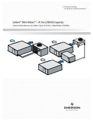
Figure 1 System configurations—air cooled systems<br />
Evaporator<br />
Figure 2 System Configurations—water/glycol systems<br />
Evaporator<br />
Water/Glycol<br />
Condensing Unit<br />
Prop Fan<br />
Condensing Unit<br />
Cooling<br />
Tower<br />
Evaporator<br />
6<br />
Centrifugal Fan<br />
Condensing Unit<br />
WATER-COOLED SYSTEMS<br />
Evaporator<br />
GLYCOL-COOLED SYSTEMS<br />
Water/Glycol<br />
Condensing Unit<br />
Site Preparation and Installation<br />
Drycooler
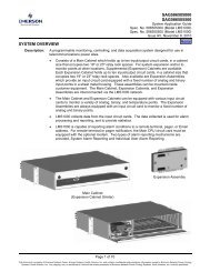
Figure 3 System Configurations—chilled water systems<br />
Evaporator<br />
CHILLED-WATER SYSTEMS<br />
2.2 System Weights<br />
Table 4 Unit weights<br />
Condensate Pump<br />
Cooling Units* lbs kg<br />
MMD96E 665 302<br />
MMD95E 665 302<br />
Condensing Units lbs kg<br />
MCD96A 530 241<br />
MCD95A 530 241<br />
MCD98W 470 213<br />
MCD97W 470 213<br />
*Add 40 lbs. (20 kg.) to units with free cooling or hot water reheat coils.<br />
2.3 Equipment Inspection upon receipt<br />
7<br />
Evaporator<br />
Site Preparation and Installation<br />
COUPLED COMPONENTS<br />
(AIR-COOLED SYSTEM<br />
Condensate Pump<br />
Condensing<br />
Unit<br />
When the unit arrives, do not uncrate equipment until it is close to its final location. All required<br />
assemblies are banded and shipped in corrugated containers. If you discover any damage when you<br />
uncrate the unit, report it to the shipper immediately. If you later find any concealed damage, report<br />
it to the shipper and to your <strong>Liebert</strong> supplier.
2.4 Installing the Evaporator or Chilled-Water Units<br />
!<br />
8<br />
Site Preparation and Installation<br />
WARNING<br />
Be sure the supporting roof structure is capable of supporting the weight of the unit(s) and the<br />
accessories during installation and service. (See 2.2 - System Weights.)<br />
Be sure to securely anchor the top ends of the suspension rods. Make sure all nuts are tight.<br />
The evaporator unit and indoor condensing unit are usually mounted above the ceiling and must be<br />
securely mounted to the roof structure. The ceiling and ceiling supports of existing buildings may<br />
require reinforcements. Be sure to follow all applicable codes. Use field-supplied 1/2"-13 tpi threaded<br />
suspension rods and 1/2"-13 tpi hardware kit.<br />
Recommended clearance between ceiling grids and building structural members is unit height plus 3<br />
inches.<br />
Install the four field-supplied rods by suspending them from suitable building structural members.<br />
Locate the rods so that they will align with the four mounting holes in the flanges that are part of the<br />
unit base.<br />
Using a suitable lifting device, raise the unit up and pass the threaded rods through the four mounting<br />
holes in the flanges that are part of the unit base.<br />
Attach the threaded rods to the unit flanges using the supplied, springs, and washers. (See Figure 4).<br />
The coil springs provide vibration isolation.<br />
1. Use the plain nuts to hold unit in place. Adjust these nuts so that the weight of the unit is<br />
supported by the four rods, does not rest on the ceiling grid, and is level. Ensure none of the<br />
springs are compressed to solid height. The coil side of the unit is heavier, so these springs will be<br />
compressed more than the other side.<br />
NOTE<br />
The units must be level in order to drain condensate properly.<br />
2. Use the Nylock nuts to “jam” the plain nuts.<br />
Figure 4 Threaded rod and hardware kit installation<br />
1" O.D. spring<br />
1/2" flat washer<br />
1/2" Nylock<br />
locking nut<br />
1/2" threaded rod<br />
(supplied by field)<br />
hanging bracket<br />
base pan (ref)<br />
1/2" hex nut
9<br />
Site Preparation and Installation<br />
2.4.1 Close Coupled Installations<br />
If the evaporator and condensing units are to be mounted side-to-side (close coupled), hang each unit<br />
before connecting them together (See Figure 5). If Single Point <strong>Power</strong> Kit is used, install the box into the<br />
evaporator prior to suspending the units. Route power wire flex conduit into condensing unit as units are<br />
suspended. Refer to instructions supplied with kit for details. Align bolt holes in the condensing unit and<br />
in the evaporator. Insert rubber spacers and secure four (4) sets of hardware provided. Align the refrigerant<br />
connections and tighten them as described in 2.4.3 - Piping Connections and Coolant Requirements.<br />
Remove “P” clamps from piping to aid fitting alignment.<br />
Figure 5 Close coupled installation<br />
Evaporator<br />
Cage<br />
nut<br />
Isolator rubber<br />
Condensing<br />
Unit<br />
5/16" lock washer<br />
5/16" capscrew<br />
5/16" flat washer<br />
NOTE: Disconnect P-clamps on lines in the evaporator<br />
for easy close coupling.<br />
P-clamps are for shipping purposes only.
2.4.2 Evaporator Air Distribution<br />
Filter Box<br />
10<br />
Site Preparation and Installation<br />
The optional filter box mounts directly to the return air opening of the evaporator. The filter box is<br />
supplied with two (2) 20% (<strong>Liebert</strong> part no. A-0320) or 30% (<strong>Liebert</strong> part no. A-0400) 25" x 20" x 4" filters.<br />
NOTE<br />
Do not operate the unit without filters installed in return air system.<br />
Connections for Ducted Systems<br />
Use flexible duct work or non-flammable cloth collars to attach duct work to the unit and to help control<br />
the transmission of vibrations to building structures. Insulation of duct work is vital to prevent<br />
condensation during the cooling cycle. The use of a vapor barrier is required to prevent absorption of<br />
moisture from the surrounding air into the insulation.<br />
If the return air duct is short, or if noise is likely to be a problem, sound-absorbing insulation should<br />
be used on the duct. Duct work should be fabricated and installed in accordance with local and<br />
national codes.<br />
Table 5 Evaporator external static pressure (60) at 3750 CFM (6371 CMH)<br />
Turns<br />
Open<br />
2 hp Motor (std) 3 hp Motor (opt)<br />
RPM<br />
External<br />
Static, in. RPM<br />
External<br />
Static, in.<br />
0 n/a n/a 1146 1.9<br />
0.5 n/a n/a 1125 1.8<br />
1 n/a n/a 1104 1.7<br />
1.5 946 0.9 1083 1.6<br />
2 922 0.8 1063 1.5<br />
2.5 972 0.7 1042 1.4<br />
3 899 0.6 1021 1.3<br />
3.5 851 0.5 1000 1.2<br />
4 828 0.4 979 1.1<br />
4.5 804 0.3 958 1.0<br />
5 780 0.2 938 0.9<br />
5.5 757 0.1 917 0.8<br />
6 733 0 896 0.7<br />
If free-cooling or hot water coil is ordered, reduce available external static<br />
pressure by 0.3" (8 mm). Contact <strong>Liebert</strong> Representative for other Air Volumes.<br />
Factory setting is 0.5" (13 mm) with 2 hp motor. Field adjust to suit application.<br />
NOTE<br />
Maximum return air static pressure should not exceed 0.3" (8 mm) to provide proper drainage<br />
of the unit.
2.4.3 Piping Connections and Coolant Requirements<br />
11<br />
Site Preparation and Installation<br />
Drain Line<br />
! CAUTION<br />
The drain line must not be trapped outside the unit, or water may back-up in drain pan.<br />
Drain is internally trapped.<br />
This line may contain boiling water. Use copper or other suitable material for the drain line.<br />
Sagging condensate drain lines may inadvertently create an external trap.<br />
A 3/4 in. (19.1 mm) female pipe thread (FPT) connection is provided for the evaporator coil condensate<br />
drain. This line also drains the humidifier, if applicable. The drain line must be located so it will not<br />
be exposed to freezing temperatures. The drain should be the full size of the drain connection.<br />
The evaporator drain pan includes a float switch to prevent unit operation if drain becomes blocked.<br />
Figure 6 Drain installation<br />
Correct<br />
Unit<br />
Continuous slope<br />
away from unit<br />
These are external traps also, although<br />
unintentional. Lines must be rigid<br />
enough to not bow between supports.<br />
Humidifier drain water can approach<br />
100° Celsius.<br />
Incorrect<br />
Unit<br />
Unit<br />
Do not externally<br />
trap the unit<br />
Incorrect
Condensate Pump<br />
12<br />
Site Preparation and Installation<br />
The optional condensate pump kit is required when the evaporator is installed below the level of the<br />
gravity-fed drain line. Refer to the installation instructions provided with the condensate pump kit.<br />
Figure 7 Condensate pump installation<br />
Condensate Pump<br />
10 9/16 "<br />
(268.3mm)<br />
6 5/8 "<br />
Condensate<br />
(168.3mm)<br />
Pump<br />
Support Bracket<br />
Drain Line<br />
(field supplied)<br />
AIR INLET<br />
3/4" (13mm) Hose Barb<br />
Supplied on Pump Tank<br />
Humidifier Water Supply Line<br />
3/8" Compression Fitting<br />
Drain Connection<br />
21 1/2 "<br />
(546mm)<br />
Flexible Rubber Tubing<br />
<strong>Power</strong> Supply from<br />
Electric Service <strong>Power</strong><br />
Block in Fan/Coil Module.<br />
Notes:<br />
1. 3/4" (13mm) Flexible Rubber Tubing Assembly (Supplied<br />
with Pump Kit) must be installed on pump end.<br />
2. The High Water Safety Float included with pump must be<br />
interlocked with unit control. Wire to terminals 60 & 61 on<br />
Evaporator terminal strip to shut down unit.<br />
3/4" (13mm) FPT<br />
Customer Connection<br />
Units supplied with the optional humidifier package have a 1/4 in. (6.4 mm) FPT connection for water<br />
inlet. Supply pressure range is 10 psig to 150 psig. Required flow rate is 1 gpm. A shut-off valve<br />
should be installed in this line to isolate the humidifier for maintenance.<br />
NOTE<br />
DO NOT route humidifier supply line in front of filter box access panel.<br />
FRONT OF UNIT<br />
Condensate Drain<br />
Evaporator or<br />
Chilled Water<br />
Unit<br />
DPN000239_Rev0
Chilled-Water Piping—Chilled-water Systems Only<br />
13<br />
Site Preparation and Installation<br />
Refer to Figure 8 for recommended field installed hardware such as shut-off valves and hose bibs.<br />
Chilled-water supply and return lines must be insulated to prevent condensation.<br />
The minimum recommended water temperature is 42°F. Connection sizes are 1-1/4" FPT.<br />
Figure 8 General arrangement diagram - chilled-water systems<br />
** Shutoff Valves<br />
** Hose Bibs<br />
Chilled<br />
Water<br />
Return<br />
Chilled<br />
Water<br />
Supply<br />
* Field piping refers to the use of hard<br />
piping using sweat adapter kit<br />
or precharged line set.<br />
** Components are not supplied by<br />
<strong>Liebert</strong> but are recommended for<br />
proper circuit operation and<br />
maintenance.<br />
Female Adapters<br />
Bleed Valve<br />
Chilled Water<br />
Control Valve<br />
Supply<br />
Return<br />
Chilled Water Coil<br />
3 - Way Chilled Water<br />
Control Valve<br />
(Optional)<br />
FIELD PIPING<br />
FACTORY PIPING<br />
DPN000236_Rev0
14<br />
Site Preparation and Installation<br />
Refrigerant (R-22) Piping<br />
All split systems require two sets of refrigerant lines (two insulated copper suction lines and two copper<br />
liquid lines) between the evaporator and the condensing unit.<br />
Two possible methods exist for installing the copper suction and liquid lines.<br />
• Close coupling the units together using the quick connects.<br />
• Using an optional Sweat Adapter Kit and hard piping between the two units.<br />
All refrigeration piping should be installed with high temperature brazed joints. Prevailing good refrigeration<br />
practices should be employed for piping supports, leak testing, evacuation, dehydration, and<br />
charging of the refrigeration circuits. The refrigeration piping should be isolated from the building by<br />
the use of vibration isolating supports. To prevent tube damage when sealing openings in walls and to<br />
reduce vibration transmission, use a soft flexible material to pack around the tubes.<br />
When installing remote condensing units above the evaporator, the suction gas line should be trapped<br />
at the evaporator. This trap will retain refrigerant oil in the off cycle. When the unit starts, oil in the<br />
trap is carried up the vertical riser and returns to the compressor.<br />
Table 6 Recommended refrigerant line sizes<br />
Equivalent<br />
Feet Circuit Liquid Line<br />
Figure 9 Refrigerant piping diagram<br />
Suction<br />
Line<br />
50 feet 3-ton 3/8" O.D. 7/8" O.D.<br />
100 feet 3-ton 1/2" O.D. 7/8" O.D<br />
150 feet 3-ton 5/8" O.D. 1-1/8" O.D<br />
50 feet 5-ton 1/2" O.D. 1-1/8" O.D<br />
100 feet 5-ton 5/8" O.D. 1-1/8" O.D<br />
150 feet 5-ton 5/8" O.D. 1-3/8" O.D<br />
Consult your <strong>Liebert</strong> representative for longer line lengths.<br />
Evaporator<br />
NOTE<br />
If field supplied refrigerant piping is installed, refrigerant (R-22) must be<br />
added to the system.<br />
Suction Line Piping<br />
Condensing Unit Below Evaporator<br />
Evaporator<br />
Pitch down 1/2" per 10 feet<br />
Condensing Unit<br />
NOTE: When installing remote condensing<br />
units below the evaporator, the suction gas<br />
line should be trapped with an inverted trap<br />
to the height of the evaporator. This<br />
prevents refrigerant migration to the<br />
compressors during off cycles. Maximum<br />
recommended vertical drop to condensing<br />
unit is 20 feet (6.1 m).<br />
Condensing Unit<br />
Suction Line Piping<br />
Condensing Unit Above Evaporator<br />
Traps recommended every 25 feet (7.6 m) of vertical rise.
15<br />
Site Preparation and Installation<br />
Refrigerant Charge Requirements: Total refrigerant charge (R-22) will be required only if units<br />
are evacuated during installation or maintenance. For safe and effective operation, refer to 2.4.3 -<br />
Piping Connections and Coolant Requirements.<br />
Total refrigerant = Units and Lines<br />
Table 7 8-ton unit refrigerant charge<br />
Evaporator<br />
Charge (ounces)<br />
Model No. 3-ton circuit 5-ton circuit<br />
MMD96E 7 7<br />
MMD95E 7<br />
Condensing Units<br />
7<br />
Model No Charge (ounces)<br />
MCD96A 361 581<br />
MCD95A 361 581<br />
MCD98W 54 94<br />
MCD97W 54 94<br />
Table 8 Line charges (field piping)*<br />
O.D. Liquid Line Suction Line<br />
1/2" 7.3 (1.1) 0.2 (0.1)<br />
5/8" 11.7 (1.7) 0.3 (0.1)<br />
7/8" 24.4 (3.6) 0.7 (0.1)<br />
1-1/8" 41.6 (6.2) 1.2 (0.2)<br />
*weight of R-22 in type “L” copper tube: lb per 100 ft (kg per 10 m)<br />
Quick Connect Fittings<br />
NOTE<br />
When hard piping is used, complete all piping and evacuate lines before<br />
connecting quick connects.<br />
Be especially careful when connecting the quick connect fittings. Read through the following steps<br />
before making the connections.<br />
1. Remove protector caps and plugs.<br />
2. Carefully wipe coupling seats and threaded surfaces with a clean cloth.<br />
3. Lubricate the male diaphragm and synthetic rubber seal with refrigerant oil.<br />
4. Thread the coupling halves together by hand to insure that the threads mate properly.<br />
5. Tighten the coupling body hex nut and union nut with the proper size wrench until the coupling<br />
bodies “bottom out” or until a definite resistance is felt.<br />
6. Using a marker or pen, make a line lengthwise from the coupling union nut to the bulkhead.<br />
7. Tighten the nuts an additional quarter-turn; the misalignment of the lines shows how much the<br />
coupling has been tightened. This final quarter-turn is necessary to insure that the joint will not<br />
leak. Refer to Table 9 for torque requirements.<br />
Table 9 Refrigerant quick connect sizes and torque<br />
Size O.D. Cu Coupling Size Torque (lb-ft)<br />
3/8" #6 10-12<br />
1/2" #10 35-45<br />
7/8" #11 35-45<br />
1-1/8" #12 50-65
Figure 10 Evaporator or chilled-water unit dimensional data<br />
26 1/2 "<br />
(673mm)<br />
19 1/2 "<br />
(495.3mm)<br />
2"<br />
(50.8mm)<br />
1 "<br />
(25.4mm)<br />
1 "<br />
(25.4mm)<br />
1 "<br />
(25.4mm)<br />
19 1/2 "<br />
(495mm)<br />
17 1/2 "<br />
(444.5mm)<br />
Duct Flange<br />
Customer Supplied<br />
threaded rods for module<br />
support from ceiling (1/2" minimum<br />
diameter recommended) (typ. 4).<br />
Air Outlet<br />
Air Inlet<br />
49 "<br />
(1244.6mm)<br />
47 "<br />
(1193.8mm)<br />
1 "<br />
(25.4mm)<br />
1 "<br />
(25.4mm)<br />
54 1/8 "<br />
(1375mm)<br />
CABINET<br />
DIMENSION<br />
50 "<br />
(1270mm)<br />
15 5/8 "<br />
(397mm)<br />
70 "<br />
(1778mm)<br />
72 "<br />
(1828.8mm)<br />
21 1/2 "<br />
(546.1mm)<br />
8 "<br />
(203mm)<br />
(OPTIONAL) FILTER BOX<br />
16<br />
1 3/16 "<br />
(30.2mm)<br />
12 1/8 "<br />
(308mm)<br />
Hanger Bracket<br />
Shaded area indicates a<br />
recommended clearance<br />
of 30" (762mm) for access<br />
and filter removal.<br />
Site Preparation and Installation<br />
16 13/16 "<br />
(427mm)<br />
50 "<br />
(1270mm)<br />
15 5/8 "<br />
(397mm)<br />
9/16" (14mm) dia. holes for<br />
threaded rods (typ. 2 each end)<br />
FRONT<br />
OF<br />
UNIT<br />
Shaded area indicates a<br />
recommended clearance<br />
of 30" (762mm) for access<br />
and filter removal.<br />
Optional 1" (25.4mm)<br />
Discharge Duct Connection<br />
ships with Filter Box<br />
16 13/16 "<br />
(427mm)<br />
DPN000240_Rev0
17<br />
Site Preparation and Installation<br />
2.4.4 Electrical Connections, Evaporator or Chilled-Water Unit<br />
! WARNING<br />
Unit contains hazardous electrical voltage. Disconnect power supply before working<br />
within. Line side of factory disconnect remains energized when disconnect is off.<br />
! WARNING<br />
UNIT CONTAINS HAZARDOUS ELECTRICAL VOLTAGE. More than one disconnect<br />
may be required to remove power. Evaporator and condensing units may have separate<br />
disconnects. Open all disconnects before working within.<br />
Each unit is shipped from the factory with internal wiring completed. Refer to electrical schematic,<br />
Figure 11, Figure 25, and Figure 26 when making connections. Electrical connections<br />
to be made at the installation site are:<br />
• <strong>Power</strong> supply to each ceiling unit and control wiring between the evaporator unit and the condensing<br />
unit, if applicable.<br />
• Control wiring between the control panel (wallbox) and the evaporator or chilled-water unit<br />
control board.<br />
<strong>Power</strong> Connections<br />
All power and control wiring and ground connections must be in accordance with the National<br />
Electrical Code (NEC) and local codes. Refer to Unit serial tag data for electrical requirements.<br />
! CAUTION<br />
Use copper wiring only. Make sure that all connections are tight.<br />
Voltage supplied must agree with the voltage specified on the unit serial tag. A field supplied disconnect<br />
switch may be required. Consult local code.<br />
Route the electrical service conduit through the hole provided in the cabinet and terminate it at<br />
the electric box. Make connections at the factory terminal block or disconnect switch, L1, L2, L3.<br />
Connect earth ground to lug provided. See transformer label for primary tap connections.<br />
Installer will need to change transformer primary taps if applied unit voltage is other than prewired<br />
tap voltage.<br />
An optional single point power kit is available for units that are close coupled (refer to Figure 11<br />
and 2.4.3 - Piping Connections and Coolant Requirements). This kit should be mounted<br />
inside the evaporator unit before installing the unit in the ceiling. Specific installation instructions<br />
are included with the single point power kit.<br />
Control Connections (10-wire on air-cooled, 8-wire on water/glycol cooled)<br />
A field-supplied control connection (24 VAC) is required between the evaporator and the condensing<br />
unit. Control wiring must be installed in accordance with the National Electrical Code (NEC)<br />
Class 2 circuit. Glycol-cooled units also require a two-wire control connection to the drycooler and<br />
pump.<br />
Control wiring between the evaporator and the condensing unit must not allow a voltage drop in<br />
the line of more than 1 volt (16 gauge minimum for 75 feet). Do not connect additional electrical<br />
devices to the control circuit. The internal control transformer is only sized for factorysupplied<br />
components.<br />
Additional control wiring will be required if your system includes other optional monitoring and<br />
control devices.<br />
Four (4) wire (thermostat type) must be connected between the evaporator control board and the<br />
wall box. See Figure 25 and Figure 26 and see Figure 11 for electrical connections.
Figure 11 Evaporator unit electrical connections<br />
Earth Ground Connection<br />
Connection terminal for field<br />
supplied earth grounding wire.<br />
High Volt <strong>Power</strong> Connections<br />
Electric service connection terminals.<br />
Microprocessor<br />
Board<br />
Optional Remote Sensor<br />
Connection P16-1,2,3,4.<br />
Field supplied unit disconnect switch<br />
when factory unit disconnect switch<br />
is not supplied.<br />
Entrance for customer high<br />
volt connections.<br />
Electrical entrance for<br />
optional condensate<br />
pump on left side of unit.<br />
Optional Single<br />
Point <strong>Power</strong> Kit<br />
FRONT OF UNIT<br />
Entrance for customer low<br />
voltage connections.<br />
Optional factory installed<br />
disconnect switch.<br />
Remote Control Panel Connection to<br />
TB3-1,2,3,4 connected with field supplied<br />
Thermostat wire (22ga, shielded/jacketed:<br />
available from <strong>Liebert</strong> or others).<br />
Heat Rejection Connection. Field supplied<br />
24V NEC Class 2 wiring TB1-10. See note 2.<br />
Remote Unit Shutdown. Use field supplied<br />
24V Class 2 wire. Replace existing jumper<br />
between TB37 & TB38 with NC switch<br />
having a minimum 75 VA rating.<br />
18<br />
Common Alarm Connection.<br />
Use field supplied 24V<br />
Class 2 wire. TB75-76.<br />
Drycooler/Circulating Pump Control<br />
Circuit TB70-71. Optional<br />
W/Glycool/Econ-O-Cycle models.<br />
Use field supplied 24V class 2 wire.<br />
Optional Condensate Pump<br />
Auxiliary Float Switch Shut<br />
Down Connection<br />
TB60-61.<br />
1<br />
2<br />
3<br />
4<br />
5<br />
6<br />
7<br />
8<br />
9<br />
10<br />
37<br />
Site Monitoring Connection.<br />
Terminals TB78 (+) TB77 (-) are for<br />
connection of a 2 wire, twisted pair,<br />
communication cable to optional<br />
sitescan.<br />
Electric service<br />
not by <strong>Liebert</strong><br />
Site Preparation and Installation<br />
60<br />
61<br />
70<br />
71<br />
75<br />
76<br />
77<br />
78<br />
84<br />
85<br />
38<br />
Field supplied, field wired thermostat wire to remote wall box.<br />
Entrance for customer low voltage connections<br />
Field supplied 24V (NEC Class2 wiring) to condensing unit. (if applicable)<br />
Customer Remote Alarm<br />
Connection TB50,51,56,24.<br />
Field supplied 24V Class 2<br />
wiring.<br />
24<br />
50<br />
51<br />
56<br />
11<br />
12<br />
Remote Humidifier Contact<br />
Field Supplied 24V class 2<br />
wiring to terminals 11 & 12,<br />
located in field wire<br />
compartment.<br />
Optional Main Fan Auxilary<br />
Side Switch TB84-85.<br />
Field supplied 24V Class 2<br />
wire.<br />
NOTES:<br />
1. Refer to specification sheet for<br />
full load amp. and wire size amp.<br />
ratings.<br />
2. Control voltage wiring must be a<br />
minimum of 16 GA (1.6mm) for up<br />
to 75’ (23m) or not to exceed 1 volt<br />
drop in control line.<br />
DPN000244_Rev0
2.5 Indoor Air-Cooled Centrifugal Fan Condensing Unit Installation<br />
2.5.1 Location Considerations<br />
19<br />
Site Preparation and Installation<br />
The centrifugal fan air-cooled condensing unit may be located above the dropped ceiling or any remote<br />
indoor area. If noise is of concern, the condensing unit should be located away from personnel. Normal<br />
operating sound may be objectionable if the condensing unit is placed near quiet work areas.<br />
To mount the unit in the ceiling, refer to 2.4 - Installing the Evaporator or Chilled-Water Units<br />
for hanging guidelines and to Figure 13 for dimensional data.<br />
2.5.2 Ducting<br />
Fan operation is designed for 5000 CFM (8495 CMH) at 0.5" external static pressure.<br />
General Considerations<br />
Use flexible duct work or nonflammable cloth collars to attach duct work to the unit and to control<br />
vibration transmission to the building. Attach the duct work to the unit using the flanges provided.<br />
Locate the unit and duct work so that the discharge air does not short circuit to the return air inlet.<br />
Duct work that runs through a conditioned space or is exposed to areas where condensation may<br />
occur must be insulated. Duct work should be suspended using flexible hangers. Duct work should not<br />
be fastened directly to the building structure.<br />
For multiple unit installations, space the units so that the hot condensing unit exhaust air is not<br />
directed toward the air inlet of an adjacent unit.<br />
Considerations for Specific Applications<br />
In applications where the ceiling plenum is used as the heat rejection domain, the discharge<br />
air must be directed away from the condensing unit air inlet and a screen must be added to the end of<br />
the discharge duct to protect service personnel. Locate the air discharge a minimum of 4 feet from an<br />
adjacent wall. Failure to do so may result in reduced air flow and poor system performance.<br />
If the condensing unit draws air from the outside of the building, rain hoods must be<br />
installed. Hood intake dimensions should be the same as the condensing unit duct dimensions. In<br />
addition, install a triple layer bird screen over rain hood openings to eliminate the possibility of<br />
insects, birds, water, or debris entering the unit. Avoid directing the hot exhaust air toward adjacent<br />
doors or windows.
2.5.3 Piping Connections<br />
20<br />
Site Preparation and Installation<br />
Details for refrigerant (R-22) loop piping are in 2.4.3 - Piping Connections and Coolant Requirements.<br />
Figure 12 Piping connections - indoor air-cooled centrifugal fan condensing unit<br />
External Equalizer<br />
2.5.4 Electrical Connections - Condensing Unit<br />
Refer to 2.4.4 - Electrical Connections, Evaporator or Chilled-Water Unit and Figure 14 for<br />
general wiring requirements and cautions. Refer to electrical schematic when making connections.<br />
Refer to unit serial tag for full load amp and wire size amp ratings.<br />
<strong>Power</strong> Connections<br />
The condensing unit requires its own power source and earth ground, with a disconnect switch to isolate<br />
the unit for maintenance.<br />
NOTE<br />
Refer to serial tag for full load amp and wire size amp ratings<br />
Control Connections<br />
Liquid Injection<br />
Valve Bulb<br />
Suction Line Male Quick<br />
Connect Coupling<br />
Suction Line Female Quick<br />
Connect Coupling<br />
*<br />
Sensing Bulb<br />
Evaporator Coil<br />
Service Access<br />
Ports<br />
Liquid Injection<br />
Valve<br />
Scroll<br />
Compressor<br />
High Pressure<br />
Switch<br />
Hot Gas Bypass<br />
Control Valve<br />
Liquid Line<br />
Solenoid Valve<br />
*<br />
Liquid Line Male Quick<br />
Connect Coupling<br />
Liquid Line Female Quick<br />
Connect Coupling<br />
Filter<br />
Drier<br />
Expansion Valve<br />
Hot Gas Bypass<br />
Solenoid Valve<br />
3 - Way Head<br />
Pressure<br />
Control Valve<br />
Condenser Coil<br />
Field-supplied control wires must be connected between the evaporator and the condensing unit (See<br />
Figure 14 and the electrical schematic on the units for more details.) Seven (7) wires are required<br />
between the evaporator and condensing unit. Eighth and ninth wires are required on systems with<br />
hot gas bypass.<br />
Check<br />
Valve<br />
Receiver Heater<br />
Pressure Limiting<br />
Switch<br />
(Two circuits required, single circuit shown for clarity)<br />
3/8" (9.5mm) FLR<br />
Pressure Relief Valve<br />
Lee - Temp<br />
Receiver<br />
Pressure Balancing<br />
Valve<br />
Sight Glass<br />
DPN000236_Rev0
Figure 13 Indoor air-cooled centrifugal condensing unit dimensions and pipe connections<br />
Customer supplied<br />
threaded rods for module<br />
support from ceiling (1/2"<br />
minimum diameter<br />
recommended) (typ. 4).<br />
13/16"<br />
(21mm)<br />
23 7/8 "<br />
(606mm)<br />
NOTE: Unit is spaced evenly in<br />
reference to threaded<br />
rod centers.<br />
Single Point <strong>Power</strong> Kit<br />
connection from Evaporator.<br />
System 1 (3<strong>Ton</strong>) Suction Line Connection,<br />
Aeroquip #11 Male.<br />
System 2 (5<strong>Ton</strong>) Suction Line Connection,<br />
Aeroquip #12 Male.<br />
System 1 (3<strong>Ton</strong>) Liquid Line Connection,<br />
Aeroquip #6 Male.<br />
System 2 (5<strong>Ton</strong>) Liquid Line Connection,<br />
Aeroquip #10 Male.<br />
42 17/32 "<br />
(1080.3mm)<br />
THREADED ROD<br />
CENTERS<br />
66 9/32 "<br />
(1683.5mm)<br />
CABINET<br />
DIMENSION<br />
59 13/16 "<br />
(1519mm)<br />
9/16" (14mm) dia. holes for<br />
threaded rods (typ. 2 each end)<br />
Air Inlet<br />
1 13/16 "<br />
(40mm)<br />
7/8" (22.2mm) dia. knockout<br />
electrical entrance for alternate<br />
control panel low voltage routing.<br />
21<br />
Air Outlet<br />
40 5/32 "<br />
(1020mm)<br />
CABINET<br />
DIMENSION<br />
64 1/4 "<br />
(1632mm)<br />
THREADED ROD<br />
CENTERS<br />
19 1/32 "<br />
(483mm)<br />
Hanger<br />
Bracket<br />
7/8" (22.2mm) dia. electrical entrance<br />
for low voltage connection.<br />
Site Preparation and Installation<br />
8 13/16 "<br />
(224mm)<br />
16 5/16 "<br />
(414mm)<br />
1 3/32 "<br />
(26mm)<br />
26 3/8 "<br />
(670mm)<br />
Shaded area indicates a<br />
recommended clearance of<br />
30" (762mm) for component<br />
access and removal.<br />
7/8" (22mm) & 1 1/8" (29mm)<br />
dia. knockouts electrical entrance<br />
for high voltage connection<br />
DPN000248_Rev1
Figure 14 Indoor air-cooled centrifugal condenser electrical connections<br />
Removable<br />
Access Panels<br />
Openings for Field Supplied<br />
24V NEC Class 2 Wiring<br />
Between Condensing Unit and<br />
Fan/Coil Unit.<br />
Line VoltageElectric <strong>Power</strong> Supply<br />
Conduit.<br />
Low VoltageElectric <strong>Power</strong><br />
Supply Conduit Entrance.<br />
6 "<br />
(152.4mm)<br />
8 1/2 "<br />
(215.9mm)<br />
12 1/2 "<br />
(317.5mm)<br />
16 1/2 "<br />
(419.1mm)<br />
22<br />
Field Supplied Unit Disconnect<br />
Switch when Factory Unit<br />
Disconnect Switch is not<br />
Supplied.<br />
Electric Service not<br />
by <strong>Liebert</strong>.<br />
4"<br />
(101.6mm)<br />
NOTES:<br />
1. Refer to specification sheet for full load amp. and wire size amp. ratings.<br />
2. Control voltage wiring must be a minimum of 16 GA (1.6mm) for up to 75’ (23m) or not<br />
to exceed 1 volt drop in control line.<br />
Site Preparation and Installation<br />
Connection Terminal for<br />
Field Supplied Earth<br />
Grounding Wire.<br />
Optional Factory Installed<br />
Disconnect Switch.<br />
Heat rejection connection . Field<br />
supplied 24V NEC class 2 wiring. See note 2.<br />
Wire connections from evaporator module:<br />
1. 24V GND System 1<br />
2. 24V Supply System 1<br />
3. High Pressure Alarm System 1<br />
4. Hot Gas Bypass Connection System 1<br />
(only on units with hot gas bypass.<br />
If no hot gas bypass, connection is<br />
provided in the evaporator module.<br />
Connect wire 4 and wire 2 to the<br />
24V supply).<br />
5. 24V GND System 2<br />
6. 24V Supply System 2<br />
7. High Pressure Alarm System 2<br />
8. Hot Gas Bypass Connection System 2<br />
(only on units with hot gas bypass.<br />
If no hot gas bypass, connection is<br />
provided in the evaporator module.<br />
Connect wire 8 and wire 6 to the<br />
24V supply).<br />
9. 24V GND Condenser Fan<br />
10. 24V SUPPLY Condenser Fan<br />
DPN000249_Rev0
2.6 Outdoor Air-Cooled Condensing Unit Installation<br />
2.6.1 Location Considerations<br />
23<br />
Site Preparation and Installation<br />
To insure a satisfactory air supply, locate air-cooled propeller fan condensing units in an environment<br />
providing clean air, away from loose dirt and foreign matter that may clog the coil. Condensing units<br />
must not be located in the vicinity of steam, hot air, or fume exhausts, or closer than 18 inches from a<br />
wall, obstruction, or adjacent unit. Avoid areas where heavy snow will accumulate at air inlet and discharge<br />
locations.<br />
The condensing unit should be located for maximum security and maintenance accessibility. Avoid<br />
ground-level sites with public access.<br />
Install a solid base, capable of supporting the weight of the condensing unit. The base should be at<br />
least 2 inches higher than the surrounding grade and 2 inches larger than the dimensions of the condensing<br />
unit base. For snowy areas, a base of sufficient height to clear snow accumulation must be<br />
installed.<br />
2.6.2 Piping Connections<br />
Details for refrigerant (R-22) loop piping are in Figure 12 - Piping connections - indoor aircooled<br />
centrifugal fan condensing unit.<br />
2.6.3 Electrical Connections<br />
Refer to 2.4.4 - Electrical Connections, Evaporator or Chilled-Water Unit for general wiring<br />
requirements and cautions. Refer to electrical schematic when making connections.<br />
<strong>Power</strong> Connections<br />
The outdoor condensing unit requires its own power source and earth ground, with a disconnect<br />
switch (field supplied) to isolate the unit for maintenance.<br />
Control Connections<br />
Field-supplied control wires must be connected between the evaporator and the condensing unit. (See<br />
Figure 6 and the electrical schematic on the units for more details.) Seven (7) wires are required<br />
between the evaporator and condensing unit. Eighth and ninth wires are required on systems with<br />
hot gas bypass.
Figure 15 Electrical field connections - outdoor condensing unit<br />
Single or three phase<br />
electric service not<br />
provided by <strong>Liebert</strong>.<br />
High voltage<br />
electric power<br />
supply entrance.<br />
Electric service<br />
connection<br />
to contactor<br />
or terminal block.<br />
Low voltage<br />
electric power supply<br />
entrance.<br />
Earth ground connection<br />
terminal for field wiring.<br />
NOTE: Refer to specification sheet<br />
for full load amp and wire size<br />
amp ratings.<br />
24<br />
Field supplied unit<br />
disconnect switch.<br />
Single or three phase<br />
electric service not provided<br />
by <strong>Liebert</strong>.<br />
Field supplied 24V NEC class 2<br />
wiring to evaporator module.<br />
Site Preparation and Installation<br />
Factory wired<br />
to components on<br />
electric panel.<br />
Heat rejection connection.Field<br />
supplied 24V NEC class 2 wiring.<br />
Wire connections from evaporator module:<br />
1 24V GND System 1<br />
2 24V Supply System 1<br />
3 High Pressure Alarm System 1<br />
4 Hot Gas Bypass Connection System 1<br />
(only on units with hot gas bypass.<br />
If no hot gas bypass, connection is<br />
provided in the evaporator module.<br />
Connect wire 4 and wire 2 to the<br />
24V supply).<br />
5 24V GND System 2<br />
6 24V Supply System 2<br />
7 High Pressure Alarm System 2<br />
8 Hot Gas Bypass Connection System 2<br />
(only on units with hot gas bypass.<br />
If no hot gas bypass, connection is<br />
provided in the evaporator module.<br />
Connect wire 8 and wire 6 to the<br />
24V supply).<br />
9 24V GND Condenser Fan<br />
10 24V SUPPLY Condenser Fan<br />
DPN000135_Rev0
Figure 16 Footprint dimensions - outdoor condensing unit<br />
LEFT<br />
AIR<br />
INTAKE<br />
GUARD<br />
HEIGHT TOP<br />
AIR<br />
DISCHARGE<br />
D<br />
B<br />
2 "<br />
(51mm)<br />
SHADED AREA<br />
INDICATES A RECOMMENDED<br />
CLEARANCE OF 18" (457mm)<br />
FOR PROPER AIR FLOW<br />
4 23/32 "<br />
(120mm)<br />
Model Dimensional Data in. (mm)<br />
60 Hz 50 Hz Width (A) Height (B) Depth (C)<br />
PFC096A-_L<br />
PFH096A-_H<br />
A<br />
36 1/8 "<br />
(918mm)<br />
25 3/32 "<br />
(637mm)<br />
PFC095A-_L<br />
PFH095A-_L<br />
REMOVABLE FRONT PANEL FOR<br />
ACCESS TO HIGH VOLTAGE &<br />
LOW VOLTAGE CONNECTIONS<br />
AND REFRIGERATION COMPONENTS<br />
46 7/32 "<br />
(1174mm)<br />
53 (1343)<br />
53 (1343)<br />
4 " TYP.<br />
(102mm)<br />
2 " TYP.<br />
(51mm)<br />
FOOTPRINT DIMENSIONS<br />
25<br />
36-1/4 (918)<br />
36-1/4 (918)<br />
53 3/16 "<br />
(1351mm)<br />
2 "<br />
(51mm)<br />
Site Preparation and Installation<br />
C<br />
38-1/2 (978)<br />
38-1/2 (978)<br />
RIGHT<br />
AIR<br />
INTAKE<br />
SHADED AREA<br />
INDICATES A RECOMMENDED<br />
CLEARANCE OF 18" (457mm)<br />
FOR PROPER AIR FLOW<br />
SHADED AREA<br />
INDICATES A RECOMMENDED<br />
CLEARANCE OF 24" (610mm)<br />
FOR COMPONENT<br />
ACCESS AND REMOVAL<br />
32 1/8 "<br />
(816mm)<br />
1/2" Bolt-Down Holes<br />
(6 places)<br />
Net Weight<br />
lbs (kg)<br />
488 (222)<br />
488 (222)<br />
2 "<br />
(51mm)<br />
DPN000131_Rev0
Figure 17 Piping and electrical connections - outdoor condensing unit<br />
26<br />
Site Preparation and Installation<br />
Model Numbers Electrical Connections In. (mm) Piping Connections In. (mm)<br />
60 Hz 50 Hz A B C D E F G<br />
PFC096A-L PFC095A-L 2<br />
(51)<br />
6<br />
(152)<br />
8-1/2<br />
(216)<br />
4-3/4<br />
(121)<br />
7-3/4<br />
(197)<br />
8-1/2<br />
(216)<br />
SL-11081Page7<br />
11-1/2<br />
(292)
2.7 Indoor Water- and Glycol-Cooled Condensing Unit Installation<br />
2.7.1 Location Considerations<br />
27<br />
Site Preparation and Installation<br />
The condensing unit may be located above the dropped ceiling or any remote indoor area. If noise is of<br />
concern, the condensing unit should be located away from personnel. Normal operating sound may be<br />
objectionable if the condensing unit is placed near quiet work areas.<br />
To mount the unit in the ceiling, refer to 2.4 - Installing the Evaporator or Chilled-Water Units.<br />
2.7.2 Piping Connections<br />
Details for Refrigerant (R-22) Loop piping are in 2.4.3 - Piping Connections and Coolant<br />
Requirements.<br />
Water/Glycol Piping Considerations<br />
Refer to Figure 20 for recommended field installed piping hardware such as shut-off valves and hosebibs.<br />
Water filters should be installed if water quality is poor. Filters will extend the service life and<br />
efficiency of the condensers.<br />
Condensing Unit Fluid Requirements<br />
The maximum fluid pressure is 150 psi standard pressure or 350 psi for high pressure units (Refer to<br />
unit serial tag and model number description page at beginning of this manual).<br />
NOTE<br />
HVAC grade ethylene or propylene glycol should be used on glycol systems.<br />
Automotive antifreeze must not be used.<br />
Regulating Valve<br />
Water/Glycol-cooled units include a coolant flow regulating valve which is factory adjusted and should<br />
not need field adjustment.<br />
Standard water pressure and high water pressure valves are adjusted differently. Contact <strong>Liebert</strong><br />
Service before making any adjustments.<br />
2.7.3 Electrical Connections<br />
Refer to 2.4.4 - Electrical Connections, Evaporator or Chilled-Water Unit for general wiring<br />
requirements and cautions. Refer to electrical schematic when making connections. Refer to serial tag<br />
for full load amp and wire size amp ratings.<br />
Control Connections<br />
A six-wire control connection is required from the evaporator unit to the water/glycol condensing unit.<br />
Two (2) additional wires are required when hot gas bypass is ordered. Glycol-cooled units also<br />
require a two-wire control connection to the drycooler and pump package.
Figure 18 Indoor water/glycol condensing unit dimensional data<br />
1. 24V GND System 1<br />
2. 24V Supply System 1<br />
3. High-Pressure Alarm<br />
System 1<br />
4. Hot Gas Bypass<br />
Connection System 1<br />
(only on units with hot<br />
gas bypass. If no hot gas<br />
bypass, connection is<br />
provided in the<br />
evaporator module.<br />
Connect wire 4 and wire 2<br />
to the 24V supply).<br />
5. 24V GND System 2<br />
6. 24V Supply System 2<br />
7. High-Pressure Alarm<br />
System 2<br />
8. Hot Gas Bypass<br />
Connection System 2<br />
(only on units with hot<br />
gas bypass. If no hot gas<br />
bypass, connection is<br />
provided in the<br />
evaporator module.<br />
Connect wire 8 and wire 6<br />
to the 24V supply).<br />
28<br />
Site Preparation and Installation
Figure 19 Indoor water/glycol condensing unit electrical field connections<br />
29<br />
Site Preparation and Installation
Figure 20 System piping with indoor water/glycol-cooled condensing unit<br />
Two circuits provided. Single circuit shown.<br />
30<br />
Site Preparation and Installation<br />
SL-11088Pg7
2.8 Optional Equipment Piping<br />
2.8.1 Free-Cooling Coil (GLYCOOL)<br />
31<br />
Site Preparation and Installation<br />
The free-cooling coil is a secondary coil located upstream of the DX coil. To take maximum advantage<br />
of available free-cooling, the secondary coil may operate at the same time as the DX coil. A temperature<br />
sensor is factory-mounted to the free-cooling piping. When fluid temperature is sufficiently below<br />
the room temperature, cooling is provided by circulating the fluid through the secondary cooling coil<br />
(flow is controlled by a motorized valve). Compressors are staged on if needed to supplement the freecooling.<br />
To keep deposits from building up in the free-cooling coil, the coil is flushed periodically.<br />
NOTE<br />
If the free-cooling coil is piped to an open water tower, a CU/NI (cupro-nickel) type coil must<br />
be ordered to prevent corrosion of the copper tubes; or a heat exchanger must separate the<br />
tower water from the free-cooling loop.<br />
On water-cooled systems, the free-cooling coil outlet can be field piped to the condensing unit inlet,<br />
provided a 3-way regulating valve has been installed within the water/glycol condensing unit (see<br />
Figure 21).<br />
Figure 21 Optional free cooling coil (3-way valve) on water/glycol units<br />
SL-11088Pg12
Figure 22 Optional free cooling coil (3-way valve) on air-cooled units<br />
SL-11088Pg12<br />
32<br />
Site Preparation and Installation
2.9 Checklist for Completed Installation<br />
33<br />
Site Preparation and Installation<br />
___ 1. Proper clearance for service access has been maintained around the equipment.<br />
___ 2. Equipment is level and lock-nuts are installed with the leveling nuts on the spring isolators.<br />
___ 3. Piping completed to refrigerant or coolant loop (if required). Refrigerant charge added (if<br />
required).<br />
___ 4. Condensate pump installed (if required).<br />
___ 5. Drain line Connected.<br />
___ 6. Water supply line connected to humidifier (if required). Route to allow air filter removal.<br />
___ 7. Field provided pan with drain installed under all cooling units and water/glycol condensing<br />
units.<br />
___ 8. Filter box installed.<br />
___ 9. Ducting completed.<br />
___ 10. Filter(s) installed in return air duct.<br />
___ 11. Line voltage to power wiring matches equipment serial tag.<br />
___ 12. <strong>Power</strong> wiring connections completed and phased correctly between disconnect switch,<br />
evaporator, and condensing unit, including earth ground.<br />
___ 13. <strong>Power</strong> line circuit breakers or fuses have proper ratings for equipment installed.<br />
___ 14. Control wiring connections completed to evaporator and condensing unit (if required,<br />
including wiring to wall-mounted control panel and optional controls).<br />
___ 15. Control panel DIP switches set based on customer requirements.<br />
___ 16. All wiring connections are tight.<br />
___ 17. Foreign materials have been removed from in and around all equipment installed (shipping<br />
materials, construction materials, tools, etc.)<br />
___ 18. Fans and blowers rotate freely without unusual noise.<br />
___ 19. Inspect all piping connections for leaks during initial operations. Correct as needed.
3.0 MICROPROCESSOR CONTROL<br />
34<br />
Microprocessor Control<br />
The Microprocessor Control for the <strong>Liebert</strong> <strong>Mini</strong>-<strong>Mate2</strong> unit features an easy to use menu-driven<br />
LCD display. The menus, control features, and circuit board details are described in this section.<br />
Detailed information concerning controls (4.0 - System Performance Microprocessor Controls)<br />
and alarms (5.0 - Alarms) are provided.<br />
3.1 Feature Overview<br />
To turn the unit ON, press the ON/OFF (I/O) key after power is applied. To turn the unit OFF, press<br />
the ON/OFF (I/O) key before power is disconnected.<br />
The following control keys may be used to move through the menus, as prompted on the LCD display:<br />
• ON/OFF (I/O) – turns unit on or off (top far left).<br />
• Menu – Enables user to access the program menu to change control parameters, alarms, setback<br />
schedule, etc. (top near left).<br />
• Increase (UP) – Raises the value of displayed parameter while in a set mode (setpoints, time, etc.)<br />
(Arrow-top near right) and navigates the program menu.<br />
• Escape (ESC) – Allows user to move back to a previous menu (top far right).<br />
• Alarm Silence/Help – If an alarm is present, pressing this keypad will silence he alarm. If this key<br />
is pressed when no alarms are present, help text will appear (bottom near left).<br />
• Decrease (DOWN) Arrow – Lowers the value of displayed parameter while in a set mode (bottom<br />
near right) and navigates the program menu.<br />
• Enter – After setting a control point, press ENTER to store the information in the microprocessor<br />
(bottom far right) Also, press ENTER to select a menu item.<br />
Figure 23 Wall box<br />
Active alarms are displayed on the LCD screen and sound an audible beeper. To silence an alarm,<br />
press the Alarm Silence/Help key as prompted on the display.<br />
Setpoints, DIP switch settings, and other selections were made during factory testing of your unit and<br />
are based upon typical operating experience. (Other default selections were made according to options<br />
included with your unit). MAKE ADJUSTMENTS TO THE FACTORY DEFAULT SELECTIONS<br />
ONLY IF THEY DO NOT MEET YOUR SPECIFICATIONS.<br />
Allowable ranges are displayed by pressing the help key. A password will be required (if enabled) to<br />
change setpoints, time delays, etc.<br />
The display normally shown includes the present room temperature, humidity, active status functions<br />
(cooling, heating, dehumidifying, humidifying), and active alarms. More detailed status and<br />
alarm information is available from the menu.
3.2 Main Menu <br />
35<br />
Microprocessor Control<br />
Press the MENU key to display the Main Menu. The Menu selections (in the following order) include:<br />
• SETPOINTS<br />
• STATUS<br />
• ACTIVE ALARMS<br />
•ALARM HISTORY<br />
•TIME<br />
•DATE<br />
• SETBACK<br />
• SETUP OPERATION<br />
• SETPT PASSWORD<br />
• SETUP PASSWORD<br />
• CALIBRATE SENSOR<br />
• ALARM ENABLE<br />
• ALARM TIME DELAY<br />
• COM ALARM ENABLE<br />
• CUSTOM ALARMS<br />
• CUSTOM TEXT<br />
•DIAGNOSTICS<br />
•end of MENU<br />
Use the UP/DOWN arrow to scroll through the selections, then, when ready to select a particular<br />
function, press ENTER.
3.3 Setpoints<br />
36<br />
Microprocessor Control<br />
Setpoints and system setup parameters are kept in nonvolatile memory. Selecting SETPOINTS from<br />
the Main Menu will display the following selections:<br />
• TEMPERATURE SETPOINT<br />
• TEMPERATURE SENSITIVITY<br />
• HUMIDITY SETPOINT<br />
• HUMIDITY SENSITIVITY<br />
• HIGH TEMPERATURE ALARM<br />
• LOW TEMPERATURE ALARM<br />
• HIGH HUMIDITY ALARM<br />
• LOW HUMIDITY ALARM<br />
Scroll through this sub-menu by using the UP/DOWN arrow, then press ENTER to select a particular<br />
function. To change a value, press ENTER and use the UP/DOWN arrows. When the value has<br />
been changed, press ENTER to store the value. For example, to change the temperature setpoint<br />
from the main status display:<br />
1. Press MENU key to display main menu.<br />
2. Scroll to “SETPOINTS” using the UP/DOWN arrow key. Press ENTER.<br />
3. Scroll to “TEMP SETPT” using the UP/DOWN arrow key. Press ENTER.<br />
4. Use the UP/DOWN arrow to change the value. Press ENTER.<br />
Table 10 Default setpoints and allowable ranges<br />
3.4 Status<br />
The operator can monitor the percentage heating, cooling, dehumidifying, and humidifying status of<br />
the unit by selecting “STATUS” from the main menu.<br />
3.5 Active Alarms<br />
The operator can monitor the alarms status by selecting “ACTIVE ALARMS” which will display a<br />
“Alarm XX of YY” alert and description. If more than one alarm is activated, use the Up/Down arrow<br />
to scroll through the alarms list. (“XX” reference is the number of the alarm shown, and the “YY” reference<br />
is the total number of alarms activated).<br />
3.6 Alarm History<br />
Setpoint Default Range<br />
Temperature Setpoint 72°F 40-90°F (5-32°C)<br />
Temperature Sensitivity 2.0°F 1-9.9°F (0.6-5.6°C)<br />
Humidity Setpoint 50% 20-80% RH<br />
Humidity Sensitivity 5% 1-30% RH<br />
High Temperature Alarm 80°F<br />
35-95°F<br />
(2-35°C)<br />
Low Temperature Alarm 65°F<br />
35-95°F<br />
(2-35°C)<br />
High Humidity Alarm 60% 15-85% RH<br />
Low Humidity Alarm 40% 15-85% RH<br />
A history of the 10 most recent alarms is kept in non-volatile memory complete with the date and<br />
time of their occurrence. The first alarm in the history is the most recent, and the 10th is the oldest. If<br />
the ALARM HISTORY is full (10 alarms) and a new alarm occurs, the oldest is lost and the newest is<br />
saved in ALARM HISTORY location 1.The rest are moved down the list by 1. ALARM HISTORY on<br />
new units may show the results of factory testing.
3.7 Time<br />
3.8 Date<br />
37<br />
Microprocessor Control<br />
The controller time clock must be set to allow for the setback control. The clock uses the 24-hour system<br />
(i.e., 12 midnight is entered 24:00). To change the time press ENTER to select the function, then<br />
use the UP/DOWN arrow to change the first character, press ENTER to store, then press the UP/<br />
DOWN arrow key to change the character, press ENTER to store, etc. The real time clock is backedup.<br />
The controller date must be set to allow for setback control. To change the date press ENTER, then<br />
use the UP/DOWN arrow to change the first character, press ENTER to store, press the UP/DOWN<br />
arrow key to change the second character, etc.<br />
3.9 Setback<br />
The microprocessor can be programmed for night and weekend setback. Two (2) events can be programmed<br />
for a five-day workweek and two (2) events can be programmed for a two-day weekend. The<br />
following table can be used to devise a setback plan.<br />
Table 11 Night and weekend setback plan<br />
3.10 Setup Operation<br />
Event Weekend Weekday<br />
Time 1<br />
Temperature1<br />
Sensitivity 1<br />
Humidity 1<br />
Humidity Sensitivity 1<br />
Time 2<br />
Temperature 2<br />
Sensitivity 2<br />
Humidity 2<br />
Humidity Sensitivity 2<br />
Selecting SETUP OPERATION from the Main Menu will display the following selections:<br />
• RESTART TIME DELAY<br />
• C/F DEGREES<br />
• HUMIDITY CONTROL METHOD<br />
• LEAD COMPRESSOR<br />
•SHOW DIP SWITCH<br />
• VALVE TIME (if valve present)<br />
• CW FLUSH (if valve present)<br />
Use the UP/DOWN ARROW to scroll through the submenu. Press ENTER to select a particular<br />
function.<br />
3.10.1 Restart Time Delay<br />
This function delays unit restart after main power is restored to the unit. If several systems are operating,<br />
the time delays should be set to different values to cause a sequential start. Delay can be set<br />
from 0.1 minutes (6 seconds to 9.9 minutes. Setting the value to zero (0) will prevent unit restart<br />
when power is restored. In this case, the unit must be restarted manually by pressing the ON/OFF<br />
button on the keypad.
3.10.2 C/F Degrees<br />
38<br />
Microprocessor Control<br />
The control may be selected to show readings and setpoints in either degrees Fahrenheit (°F) or in<br />
degrees Celsius (°C). To change the value use ENTER to select this function, then use the UP/DOWN<br />
arrow to change the value. Press ENTER to store the value.<br />
3.10.3 Humidity Control Method<br />
The operator may select either relative (direct) or absolute (predictive) humidity control. If “relative”<br />
is selected, the RH control is taken directly from the RH sensor. If “absolute” is selected, the RH control<br />
is automatically adjusted whenever return air temperature deviates from the desired temperature<br />
setpoint (i.e., predictive humidity control). The LCD display will indicate percentage relative<br />
humidity for both methods of control. If the “absolute” feature is selected, the adjusted humidity reading<br />
will also be shown. When utilizing the predictive humidity control feature, the humidity level is<br />
automatically adjusted ~2% RH for each degree difference between the return air temperature and<br />
the temperature setpoint.<br />
Unnecessary dehumidification can result when overcooling occurs during a dehumidification cycle.<br />
This is due to a higher than normal RH reading caused by overcooling the room (about 2% RH for<br />
each degree of overcooling). This drop in temperature extends the dehumidification cycle. Later, when<br />
the dehumidification ends and the temperature rises to the setpoint, the RH reading falls. The final<br />
RH reading will then be lower than actually desired. If the temperature drop was significant enough,<br />
the percentage RH could be low enough to activate the humidifier.<br />
If the absolute humidity control is selected, over-dehumidification may be avoided. When overcooling<br />
occurs (i.e., causing an increase in the RH reading) the humidity control program estimates what the<br />
RH will be when the dehumidification cycle ends and temperature returns to the setpoint. This allows<br />
the dehumidification cycle to end at the proper time. Predictive humidity control can greatly reduce<br />
energy consumption by minimizing both compressor/reheat operation. Use the UP/DOWN ARROW<br />
key to select the desired humidity control method.<br />
3.10.4 Lead Compressor<br />
This function allows the user to select which compressor is the lead: Compressor 1 (3 ton), Compressor<br />
2 (5 ton), or Auto. The factory default is Auto. If Auto is selected, the control will determine which<br />
compressor is to be the lead compressor based on the average room load over the previous one hour of<br />
operation.<br />
3.10.5 Show DIP Switch<br />
This function shows the position of the DIP switches which are located on the control board in the<br />
unit. 1 = Switch is “ON” and 0 = Switch is “OFF”. For more information on the DIP switches and their<br />
functions, see Table 17 Equipment Switch Settings.<br />
3.10.6 Valve Time (For Systems With a Modulating Chilled-Water Valve)<br />
This function shows the full valve travel time of the modulating valve on a chilled-water system. This<br />
is the time it takes for the valve to travel from full closed to full open. It is programmable from 50 to<br />
250 seconds; factory default time is 165 seconds and should not be changed unless actual valve travel<br />
time is not correct. The full valve travel time is used by the control to determine the appropriate valve<br />
position. For example, if the valve travel time is 165 seconds and 50% cooling is being called for, the<br />
valve will open for 83 seconds to achieve 50% open.
3.10.7 CW Flush (For Systems With a Modulating Chilled-Water Valve)<br />
39<br />
Microprocessor Control<br />
This function shows the interval time at which the system will perform a modulating chilled-water<br />
valve system flush cycle. The factory default is 24 (hours) and is programmable from 0 (hours) which<br />
signifies to never flush, to 99 (hours) which signifies to flush after every 99 hours of valve non-use. If<br />
the valve is called on by the control to open within the programmed interval time, the timer will be<br />
reset to 0. The flush cycle is active even when the fan is turned off, but power is applied to the unit.<br />
When the interval timer reaches the programmed time, the valve will be opened for 3 minutes to flush<br />
any contaminates which may have collected in the system.<br />
Table 12 Setup functions, default values and allowable ranges<br />
3.11 Change Passwords<br />
The display will prompt the operator to enter a three digit password when attempting to make<br />
changes. The system includes two (2) passwords, one for setpoints and one for setup. The system<br />
allows the password to be changed by first entering the default password set at the factory (1-2-3) for<br />
setpoints and (3-2-1) for setup. The password function provides system security, so that only authorized<br />
personnel are allowed to make changes to the system. (If unauthorized changes are being made,<br />
the passwords may be compromised and new ones should be selected). The password function can be<br />
disabled by setting DIP switch 8 in the wallbox to OFF, then resetting power to the unit.<br />
3.12 Calibrate Sensors<br />
The temperature and humidity sensors can be calibrated by selecting the CALIBRATE SENSORS<br />
menu item. The temperature sensor can be calibrated ±5°F, while the humidity sensor can be calibrated<br />
±10% RH. When calibrating the humidity sensor, the value shown will always be % RH, even<br />
though absolute humidity control may be selected. If absolute humidity control is selected, the Normal<br />
Status Display will display the adjusted reading. This reading may not agree with the relative<br />
humidity reading displayed while in calibration.<br />
If the sensors are subject to frequent wide temperature and humidity swings, it may be necessary to<br />
shorten the cycling by increasing the sensor response time delay. If the sensors are located too close to<br />
the air discharge, they will likely experience rapid swings in measurement. The factory default is 30<br />
seconds. Another method in reducing compressor cycling is to increase the temperature and/or humidity<br />
sensitivity.<br />
3.13 Alarm Enable<br />
Function Default Range<br />
Restart Time Delay 0.1<br />
0 to 9.9 min<br />
(0 = manual restart)<br />
C/F Degrees °F °C or °F<br />
Humidity Control Rel Relative or Absolute<br />
Valve Time 165 50 to 250 sec(s)<br />
CW Flush 24 0 to 99 hours<br />
Each alarm can be disabled or enabled. Use the UP/DOWN ARROW to select a particular alarm,<br />
press Enter to select either enable or disable. Then press Enter again to store the change. When the<br />
alarm is disabled it will NOT report to either the wallbox beeper or the common alarm relay. The high<br />
water in condensate pan and high head alarms cannot be disabled.<br />
NOTE<br />
The high-water alarm will automatically shut the unit off.
3.14 Alarm Time Delay<br />
40<br />
Microprocessor Control<br />
Each individual alarm can be programmed with a time delay (Table 13), causing the unit to delay a<br />
specified amount of time (0-255 seconds) before recognizing the alarm. The alarm condition must be<br />
present for the full amount of the time delay before the alarm will sound. If the alarm condition is<br />
diverted prematurely, the alarm will not be recognized and the time delay will automatically reset.<br />
3.15 Common Alarm Enable<br />
Each individual alarm can be selected to activate/deactivate the common alarm relay. If the energize<br />
common alarm function is set to YES, the relay is energized immediately as the alarm is enunciated,<br />
and de-energized when the alarm condition has cleared. If the alarm is completely DISABLED, the<br />
alarm has no effect on the common alarm relay. Use the UP/DOWN arrows to scroll to a particular<br />
alarm, press the ENTER button to select it, then press the ENTER key again to select Yes or No.<br />
3.16 Custom Alarms<br />
NOTE<br />
For software alarms such as “loss of power” and “short cycle,” the time<br />
delay should be left at the factory default of 0.<br />
Table 13 Alarm default time delays<br />
Alarm<br />
The custom alarm messages can be selected from a list of standard alarm messages, or the operator<br />
can write his/her own message. A MAXIMUM OF THREE (3) ALARM MESSAGES CAN BE CUS-<br />
TOMIZED.<br />
The text for custom alarms can be changed at any time by selecting “CUSTOM ALARMS”. To change<br />
the text for a custom alarm, select the alarm you would like to change, 1, 2 or 3. Using the UP/DOWN<br />
arrows, step through the list of seven standard alarm messages (listed below) and two custom alarms.<br />
Select the alarm message desired and store it by pressing ENTER.<br />
• SMOKE DETECTED<br />
•CUSTOM 2<br />
•CUSTOM 3<br />
• STANDBY GC PUMP<br />
• WATER FLOW LOSS<br />
• STANDBY UNIT ON<br />
•CUSTOM 1<br />
Default Time Delay<br />
(seconds)<br />
Hum Prob 2<br />
Chng Fltr 2<br />
Custom Alarm #1 0<br />
Custom Alarm #2 0<br />
Custom Alarm #3 0<br />
High Temperature 30<br />
Low Temperature 30<br />
High Humidity 30<br />
Low Humidity 30<br />
Short Cycle 1 & 2 0<br />
Loss of <strong>Power</strong> 0
3.17 Custom Text<br />
41<br />
Microprocessor Control<br />
To modify the two custom alarm messages select “CUSTOM TEXT”. Then select “Custom Text #1,”<br />
“Custom Text #2” or “Custom Text #3.” Text can be up to 16 characters in length and can be either a<br />
blank space or any of the following alphanumeric characters and symbols:<br />
• A,B,C,D,E,F,G,H,I,J,K,L,M,N,O,P,Q,R,S,T,U,V,W,X,Y,Z<br />
• #,%,*,-<br />
• 0,1,2,3,4,5,6,7,8 or 9<br />
Use the UP/DOWN arrows to select a character, then press ENTER. The cursor will move to the<br />
next space where you may once use the UP/DOWN arrows to select another character, etc. The custom<br />
text alarm will be displayed only if the alarm is selected in Custom Alarms.<br />
LCD Display Contrast<br />
The level of contrast due to the viewing angle of the LCD display can be adjusted using a potentiometer<br />
screw, inside the wall box next to the display.<br />
Nonvolatile Memory<br />
All critical information is stored in nonvolatile memory. Setpoints and setup parameters are kept<br />
inside the microcontroller in EEPROM.<br />
Equipment Options Switches<br />
Equipment options are selected and enabled using DIP switches 1 through 7. These are located on the<br />
control board near TB3. These switches are factory set and should not require any user changes. The<br />
setting and function of the switches can be individually read on the LCD display.<br />
NOTE<br />
In order to update the DIP switch settings, power must be cycled off, then on, from the unit<br />
disconnect switch.<br />
Table 14 Equipment switch settings (unit control board)<br />
Switch OFF Position ON Position<br />
1 Step Cool Ramp Cool<br />
2 Step Heat Ramp Heat<br />
3 Not Used Not Used<br />
4 No GLYCOOL GLYCOOL<br />
5 Disable 1 stage CW Enable 1 stage CW<br />
6 Not used Not used<br />
7 1-stage<br />
2-stage<br />
dehumidification dehumidification<br />
8 Disable SCR Reheat Enable SCR Reheat<br />
Table 15 Switch settings (wallbox board)<br />
Switch OFF Position ON Position<br />
1 Beeper Disable Beeper Enable<br />
2 Not Used Not Used<br />
3 Not Used Not Used<br />
4 Enable Reheat Disable Reheat<br />
5 Enable Hum. Disable Hum.<br />
6 Enable Dehum. Disable Dehum.<br />
7 Disable Setback Enable Setback<br />
8 Enable Password Disable Password
3.18 Run Diagnostics<br />
42<br />
Microprocessor Control<br />
By selecting Run Diagnostics, maintenance personnel can check system inputs, outputs, and conduct<br />
a test of the microcontroller circuit board from the wall box control. A review of the system inputs and<br />
the microcontroller test can be done without interrupting normal operation.<br />
Test Outputs<br />
• When this feature is selected, the controller is effectively turned off. When stepping from one load<br />
to the next, the previous load is automatically turned off. The loads can also be toggled on/off by<br />
selecting “ENTER”. Once turned on, the output will remain on for five minutes unless toggled off<br />
or the test outputs function is exited by selecting “MENU/ESC” (Compressor is limited to 15 seconds<br />
on to prevent damage.<br />
! CAUTION<br />
Testing compressor output for more than a few seconds could damage the compressor. To<br />
eliminate damaging the compressor during testing, DO NOT test compressor output for more<br />
than a few seconds.<br />
! CAUTION<br />
Extended unit operation in the test outputs mode for troubleshooting may cause damage to<br />
unit. DO NOT operate unit in the test outputs mode any longer than is necessary for<br />
troubleshooting.<br />
NOTE<br />
Fan turned on with all loads.<br />
The outputs are:<br />
•Main Fan<br />
• Compr1 (3-ton)<br />
• Compr1 & HGBP1<br />
• Compr2<br />
• Compr2 & HGBP2<br />
• Compr1 & Compr2<br />
• Chill Water/Gly (if present)<br />
• Reheat 1<br />
• Reheat 2<br />
• SCR Reheats (if present)<br />
• Humidifier<br />
• Common Alarm<br />
Test Inputs<br />
With the unit on and the fan running, the input states may be displayed for the following devices:<br />
•Input <strong>Power</strong><br />
• High Water in Pan<br />
• High Head Comp1<br />
• High Head Comp2<br />
• Air Sail Switch (requires additional factory-installed components)<br />
•Filter Clog<br />
• Humidifier Prob.<br />
• Custom Alarm #1<br />
• Custom Alarm #2<br />
• Custom Alarm #3
Test Micro<br />
43<br />
Microprocessor Control<br />
By selecting this function, the microcontroller will perform a self test lasting approximately 10 seconds.<br />
When the test is complete, the display will show the ROM checksum, ROM part number, and<br />
firmware revision number.<br />
Figure 24 Control menu<br />
Status Display<br />
72 F 50 %RH<br />
NO ALARMS<br />
Menu<br />
Setpoints<br />
Status<br />
Active Alarms<br />
Alarm History<br />
Time<br />
Date<br />
Setback<br />
Setup Operation<br />
Setpoint<br />
Password<br />
Setup Password<br />
Calibrate Sensor<br />
Alarm Enable<br />
Alarm Time Delay<br />
Com Alarm<br />
Enable<br />
Custom Alarms<br />
Custom Text<br />
Diagnostics<br />
End of Menu<br />
Setpoints<br />
Temp Setpt<br />
Temp Sens<br />
Hum Setpt<br />
Hum Sens<br />
Hi Temp Alm<br />
Lo Temp Alrm<br />
Hi Hum Alm<br />
Lo Hum Alm<br />
Status<br />
Dx Cool % 0<br />
CW Valve% 0<br />
Econo Cool %0<br />
Heat % 0<br />
Dehumidify% 0<br />
Humidify% 0<br />
Active Alarms<br />
No Alarms<br />
or<br />
Alarm 01 of 01<br />
High Head<br />
Time<br />
Date<br />
Setback<br />
Wknd Time 1<br />
On/Off:<br />
Wknd Temp 1<br />
Wknd Tsens 1<br />
Wknd Humd 1<br />
Wknd Hsens 1<br />
Wknd Time 2<br />
On/Off:<br />
Wknd Temp 2<br />
Wknd Tsens 2<br />
Wknd Humd 2<br />
Wknd Hsens 2<br />
Wkdy Time 1<br />
On/Off:<br />
Wkdy Temp 1<br />
Wkdy Humd 1<br />
Wkdy Hsens 1<br />
Wkdy Time 2<br />
On/Off:<br />
Wkdy Temp 2<br />
Wkdy Tsens 2<br />
Wkdy Humd 2<br />
Wkdy Hsens 2<br />
Setup Operation<br />
Restart TD<br />
C/F Degrees<br />
Humidity Control<br />
Lead Compr<br />
Dipswch 00000000<br />
Pos 12345678<br />
Valve Time<br />
CW Flush<br />
Setpoint Password<br />
Enter New PSW<br />
Setpt PSW = 000<br />
Setup Password<br />
Enter New PSW<br />
Setup PSW = 000<br />
Calibrate sensor<br />
Temp Cal<br />
Hum Cal<br />
Temp Delay<br />
Hum Delay<br />
Alarm Enable<br />
Hum Prob<br />
Chng Fltr<br />
Loss Air<br />
Custom #1<br />
Custom #2<br />
Custom #3<br />
High Temp<br />
Low Temp<br />
High Hum<br />
Low Hum<br />
Short Cyc1<br />
Short Cyc2<br />
Fan Ovrld<br />
Loss Pwr<br />
Alarm Time Delay<br />
Hum Prob<br />
Chng Filt<br />
Loss Air<br />
Custom #1<br />
Custom #2<br />
Custom #3<br />
High Temp<br />
Low Temp<br />
High Hum<br />
Low Hum<br />
Short Cyc1<br />
Short Cyc2<br />
Fan Ovrld<br />
Loss Pwr<br />
Com Alarm Enable<br />
Hum Prob<br />
Hi Head 1<br />
Hi Head 2<br />
Chng Fltr<br />
Loss Air<br />
Custom #1<br />
Custom #2<br />
Custom #3<br />
Hi Water<br />
High Temp<br />
Low Temp<br />
High Hum<br />
Low Hum<br />
Short Cyc1<br />
Short Cyc2<br />
Fan Ovrld<br />
Loss Pwr<br />
Custom Alarms<br />
Custom Alarm #1<br />
Custom Alarm #2<br />
Custom Alarm #3<br />
Custom Text<br />
Custom Text #1<br />
Custom Text #2<br />
Custom Text #3<br />
Diagnostics<br />
Test Outputs<br />
Test Inputs<br />
Test Microcontroller
Figure 25 Control board (inside evaporator)<br />
P32<br />
P36<br />
P8<br />
P33<br />
P34<br />
P22<br />
P40<br />
P38<br />
P39<br />
P3<br />
Figure 26 Wall box board<br />
TB3-1<br />
TB3-2<br />
TB3-3<br />
TB4-4<br />
P35<br />
P7<br />
P2<br />
P18<br />
P1<br />
P25<br />
P4<br />
TB<br />
44<br />
T+<br />
T-<br />
+5V<br />
GND<br />
P26<br />
P5<br />
P16<br />
P10<br />
G2 G3 G4 G5<br />
P43<br />
Microprocessor Control<br />
TB3-4 Connection to Terminal #4 Wallbox<br />
TB3-3 Connection to Terminal #3 Wallbox<br />
TB3-2 Connection to Terminal #2 Wallbox<br />
TB3-1 Connection to Terminal #1 Wallbox<br />
P16 Remote Sensor Connection<br />
Wall Box<br />
DIP Switches (1-8)
4.0 SYSTEM PERFORMANCE MICROPROCESSOR CONTROLS<br />
4.1 Control Type Response Proportional Control<br />
45<br />
System Performance Microprocessor Controls<br />
The percent requirement is determined by the difference between the return air temperature and the<br />
temperature setpoint. As the return air temperature rises above the temperature setpoint, the percent<br />
cooling required increases proportionally (from 0 to 100%) over a temperature band equal to the<br />
temperature sensitivity plus 1 degree Fahrenheit. The heating requirement is determined in a similar<br />
manner as the temperature decreases below the setpoint. With this control type the temperature<br />
at which the room is controlled increases as the room load increases. At full load the room would be<br />
controlled at a temperature equal to the setpoint plus the sensitivity.<br />
4.2 Cooling<br />
4.2.1 Multi-Step Cooling, Compressorized Direct Expansion (DX) Systems<br />
The system will use the 3-ton (compressor #1) and 5-ton (compressor #2) compressors in an 8-ton system.<br />
The control will determine the average cooling requirement updated every hour and select the<br />
lead compressor or, the user can select the lead compressor through the “Setup Operation” menu. At<br />
startup, the 3-ton compressor will be the lead compressor. The compressors will be staged on with hot<br />
gas bypass energized at 50 and 100% cooling requirements. The compressors will turn off at 75% and<br />
25% requirements.<br />
4.2.2 Chilled-Water Cooling (8 <strong>Ton</strong>)<br />
The chilled-water control valve is adjusted proportionally as the temperature control varies the<br />
requirement for cooling from 0% to 100%. This is based on the full valve travel time programmed in<br />
the “Setup Operation” menu.<br />
4.2.3 GLYCOOL Cooling (8 <strong>Ton</strong>)<br />
When GLYCOOL is available, the temperature control will calculate a total cooling requirement of<br />
200%. Assuming that full GLYCOOL capacity is available, the GLYCOOL valve opens proportionally<br />
as the requirement for cooling rises from 0 to 100%. If the call for cooling continues to increase, the<br />
control will energize the compressors as needed to match the average cooling requirement. As long as<br />
GLYCOOL is available, the control will leave the valve 100% open. If GLYCOOL cooling is not available,<br />
the temperature control will operate the compressors in the same manner as the Multi-Step<br />
without GLYCOOL.<br />
4.3 Reheat<br />
4.3.1 Electric Reheat - Staged<br />
For 2-stage electric reheat, they are activated when the temperature control calculates a requirement<br />
of 50% and 100%. They are deactivated when the requirement decreases to 75% (reheat 2) and 25%<br />
(reheat 1).<br />
4.3.2 SCR Electric Reheat<br />
The SCR (Silicon Controlled Rectifier) controller shall proportionally control the stainless steel<br />
reheats to maintain the selected room temperature. The rapid cycling made possible by the SCR controller<br />
provides precise temperature control, and the more constant element temperature extends<br />
heater life. During operation of the SCR control, the compressor(s) operate(s) continuously. The heaters<br />
are modulated to provide temperature control. If overcooling occurs, the compressor(s) will be<br />
locked off when the temperature drops to the low temperature alarm. SCR reheats are 15 kW.
4.4 Dehumidification / Humidification Percent Required<br />
46<br />
System Performance Microprocessor Controls<br />
The humidity control for the MM2 is based on a calculated percent requirement for dehumidification<br />
or humidification. The percent requirement is calculated from the difference between the sensor reading<br />
and the humidity setpoint, divided by the sensitivity. The control method is selectable between<br />
relative and absolute. Relative humidity control is the default.<br />
4.4.1 Staged Dehumidification, Compressorized Direct Expansion (DX) Systems<br />
For the 8-ton unit operation, 1 or 2 stage dehumidification is selected through DIP switch #7. For 2<br />
stages, the 5-ton compressor is the lead compressor when dehumidifying. Dehumidification will be<br />
staged on at 50 and 100% call. The electric reheats are turned on at 25% cooling (reheat 1) and 25%<br />
heating (reheat 2) for improved temperature control. The reheats are deactivated at 0% and 50% cooling<br />
requirement, respectively. If overcooling occurs, the first stage of dehumidification is disabled at<br />
125% call for heating. If 1 stage or 2 stage is selected, dehumidification is disabled at 200% call for<br />
heating. Dehumidification is re-enabled at 66% call for 2 stage and 33% call for 1 stage. For optional<br />
hot water heating, the valve is energized at its normal point, 100% heating requirement.<br />
4.4.2 Humidification Operation<br />
System Activation<br />
The humidifier is activated when the humidity control calculates a requirement for 100% humidification,<br />
and is deactivated when the requirement falls below 50%.<br />
4.4.3 Dehumidification Lockout<br />
Dehumidification is locked out if overcooling occurs. Dehumidification on the 8-ton unit is disabled at<br />
125% (first stage) and 200% (all stages) heating requirement. Dehumidification is re-enabled at 66%<br />
and 33% heating requirement.<br />
4.5 Load Control Features<br />
The control system monitors the compressor and prevents it from turning on within a 3-minute period<br />
of being off. If this on-off cycle occurs to often (e.g. 10 times within a one hour period) a Short Cycle<br />
Alarm will occur.<br />
4.6 Communications<br />
The control system uses a two-wire, RS-422 channel to communicate with <strong>Liebert</strong> Site Products via a<br />
proprietary protocol. A converter board (ECA2) is available to allow communications with a “dumb”<br />
terminal or a computer using RS-232 channel. More details are provided in the Site Products and<br />
ECA2 User Manual.<br />
The communications channel provides both monitoring and control options, including:<br />
• TEMPERATURE/HUMIDITY: Current temperature and humidity readings.<br />
• STATUS (%), Cooling/heating and humidify/dehumidify operating status.<br />
• PRESENT ALARMS: Alarms currently activated.<br />
• SETPOINTS:<br />
• Temperature Setpoint<br />
• Temperature Sensitivity<br />
•Humidity Setpoint<br />
• Humidity Sensitivity<br />
• High Temperature Alarm<br />
• Low Temperature Alarm<br />
• High Humidity Alarm<br />
• Low Humidity Alarm<br />
• ON/OFF STATUS and CONTROL<br />
• SILENCE ALARM
5.0 ALARMS<br />
47<br />
Alarms<br />
The microprocessor control system will audibly and visually signal all ENABLED Alarms (including<br />
two (2) custom alarms). These special alarms can be chosen from the optional alarm list and/or can<br />
have their own fully custom text. The custom alarm inputs are contact closures wired from terminal<br />
24 through a normally open contact to either 50 (alarm 1), 51 (alarm 2), or 56 (alarm 3). The alarms<br />
can be enabled/disabled (refer to 3.0 - Microprocessor Control) and a time delay of 0-255 seconds<br />
can be set. The alarms can also be programmed to either sound the alarm & activate the common<br />
alarm relay OR to sound the alarm only.<br />
When a new alarm occurs, it is displayed on the screen and the audible alarm is activated. (If communicating<br />
with a <strong>Liebert</strong> Site Product, the alarm is also transmitted). The message “PRESS ALARM<br />
SILENCE” will prompt the operator to silence the alarm. After the alarm is silenced, the display will<br />
return to the Normal Status Display. Alarms can be reviewed by selecting the “ACTIVE ALARMS”<br />
feature. The alarms can also be silenced through communications with a <strong>Liebert</strong> Site Products Unit.<br />
Many alarms will reset automatically when the alarm condition is no longer present and only after it<br />
has been acknowledged by being “Silenced.” The exceptions are:<br />
1. Software alarms, i.e., Loss of <strong>Power</strong> and Short Cycle alarms will reset automatically 30 seconds<br />
and 90 minutes respectively, after being silenced or acknowledged; and<br />
2. Specific alarms monitoring overload or high pressure switches may require a manual reset<br />
depending upon the model.<br />
5.1 Alarms: Definitions and Troubleshooting<br />
The following list provides a definition and troubleshooting suggestions for each type of alarm. Refer<br />
to 8.0 - Troubleshooting for additional details. If you need further assistance, contact your <strong>Liebert</strong><br />
supplier. THE CUSTOMER MUST SPECIFY ALARM(S) AT THE TIME OF ORDER. OTHER<br />
DEVICES AND WIRING MAY BE REQUIRED AT THE FACTORY FOR SOME OF THE ALARMS.<br />
5.1.1 Custom Alarms<br />
Custom alarm(s) messages are programmed at the LCD display. The message displayed may be<br />
included in a list of provided alarms or it may be customized text (for up to three alarms). IF CUS-<br />
TOMIZED TEXT IS USED, MAINTENANCE PERSONNEL SHOULD BE INFORMED OF THE<br />
ALARM FUNCTION AND THE REQUIRED ACTION.<br />
5.1.2 High Head Pressure<br />
Compressor head pressure is monitored with a pressure switch. (One SPDT pressure switch is used).<br />
If head pressure exceeds 360 psig, the switch turns off the compressor contactor and sends an input<br />
signal to the control. The condition is acknowledged by pressing the alarm silence button on the wall<br />
box, which will clear if the head pressure is alleviated. If the head pressure alarm has activated three<br />
times, the alarm will lock until the unit is serviced. After the head-pressure problem is fixed, reset the<br />
control by disconnecting power to the evaporator unit.<br />
Air-Cooled Systems<br />
Check for power shut off to the condenser, condenser fans not working, defective head pressure control<br />
valves, dirty condenser coils or crimped lines.<br />
Water/Glycol Systems<br />
Check water regulating valves. Verify water/glycol flow (i.e., pumps operating and service valves<br />
open). Is water tower or drycooler operating? Is the coolant temperature entering the condenser at or<br />
below design conditions? Is AUX relay (terminals 70 & 71) operating during cooling to turn on the<br />
drycooler?
5.1.3 Humidity<br />
The humidity alarm may be activated under the following conditions:<br />
48<br />
Alarms<br />
• High: The room return air humidity exceeds the pre-set high humidity alarm setpoint. Is the unit<br />
set up for dehumidification? Check DIP switch.<br />
• Low: The room return air humidity decreases to the low humidity alarm setpoint. Is the unit<br />
setup for humidification? Check DIP switch.<br />
• High and Low Humidity (simultaneously): The simultaneous display of two alarms results in<br />
loss of the humidity input signal. DASHES WILL BE DISPLAYED IN THE HUMIDITY READ-<br />
ING DISPLAY. Under these conditions, the control system deactivates both humidification and<br />
dehumidification. Check for a disconnected cable or failed sensor.<br />
5.1.4 Temperature<br />
NOTE<br />
Check for proper setpoints. Does the room have a vapor barrier to seal it<br />
from outdoor humidity? Are doors or windows open to outside air?<br />
The temperature level alarm may be activated under the following conditions:<br />
• High: The room return air temperature increases to the high temperature alarm setpoint. Check<br />
for proper setpoint value. Is the room load more than the unit can handle (i.e., capacity too small)?<br />
Make sure cooling components are operating (compressor or valves).<br />
• Low: The room return air temperature decreases to the low temperature alarm setpoint. Check<br />
for proper setpoint value. Make sure all heating components are operating (e.g., contactors,<br />
reheats, etc.). Are reheats drawing the proper current (refer to amp rating on nameplate).<br />
• High and Low (simultaneously): The simultaneous display of these two alarms results in loss<br />
of the temperature input signal (or the humidity is out of sensor range-15 to 85% RH). Dashes will<br />
be displayed for the temperature reading. The control system will initiate 100% cooling. Check for<br />
a disconnected cable or a failed sensor.<br />
5.1.5 Humidifier Problem Alarm<br />
The Humidifier Problem Alarm will sound and display a message if any of the following humidifier<br />
conditions occur: overcurrent detection; fill system fault or end of cylinder life.<br />
Check fault indicator LED on humidifier control board:<br />
• Constant LED on = Overcurrent<br />
• 1 second LED Flash = Fill System Fault<br />
• 1/2 second LED Flash = End of cylinder life, replace tank<br />
5.1.6 High-Water Alarm<br />
A float switch in the evaporator pan will shutdown the evaporator on a high water level. Clear the<br />
drain and reset power to the unit in order to clear the alarm.<br />
5.1.7 Loss of <strong>Power</strong><br />
The Loss of <strong>Power</strong> Alarm will activate (after power is restored to the unit) if the unit has lost power or<br />
the disconnect switch was incorrectly turned off before the unit ON/OFF switch was pressed. A <strong>Liebert</strong><br />
remote monitoring unit (optional) will immediately indicate loss of power.<br />
5.1.8 Short Cycle<br />
A Short Cycle Alarm will occur if a compressor system has exceeded 10 cooling start attempts in a<br />
one-hour period. This can be caused by room cooling load is small compared to capacity of the unit. If<br />
room load is low, increase temperature sensitivity to reduce cycle.
5.2 Optional/Custom Alarms<br />
5.2.1 Change Filter<br />
49<br />
Alarms<br />
Periodically, the return air filters in the evaporator must be changed. The Change Filter alarm notifies<br />
the user that filter replacement is necessary. A differential air pressure switch closes when the<br />
pressure drop across the filters becomes excessive. The switch is adjustable using the procedure on<br />
the switch label.<br />
5.2.2 Firestat<br />
The optional firestat feature is a bi-metal operated sensing device with a closed switch under normal<br />
conditions. Connected between pins 1-8 and 1-9, this device will shut down the entire unit.<br />
5.2.3 Smoke Detector<br />
The smoke detector is located in the unit, the optional smoke detector power supply is located in the<br />
electric panel. It constantly samples return air through a tube. No adjustments are required.
6.0 SYSTEM OPERATION, TESTING, AND MAINTENANCE<br />
50<br />
System Operation, Testing, and Maintenance<br />
This section describes system testing, maintenance and replacement procedures. Use copies of the<br />
Maintenance Inspection Checklist to record preventive maintenance inspections.<br />
! WARNING<br />
Unit contains hazardous electrical voltage. Disconnect power supply before working within.<br />
Line side of factory disconnect remains energized when disconnect is off.<br />
6.1 System Testing<br />
6.1.1 Environmental Control Functions<br />
The performance of all control circuits can be tested by changing the setpoints, which activates each<br />
of the main functions.<br />
6.1.2 Cooling<br />
To test the cooling function, set the setpoint to a temperature of 10°F (5°C) below room temperature.<br />
A call for cooling should register and prompt the equipment to begin cooling cycle. (Disregard any<br />
temperature alarms). Upon completion of testing, return setpoint to the desired temperature.<br />
6.1.3 Heating<br />
Reheat may be tested by setting the setpoint 10°F (5°C) above room temperature. A call for heating<br />
should register and prompt the equipment to begin heating cycle. (Disregard any temperature<br />
alarms). Upon completion of testing, return setpoint to the desired temperature.<br />
6.1.4 Humidification<br />
To check humidification, set the humidity setpoint at RH 10% above the room humidity reading. After<br />
a short delay, the canister will fill with water and steam will be produced. Upon completion of testing,<br />
return the humidity setpoint to the desired humidity.<br />
6.1.5 Dehumidification<br />
The dehumidification performance can be tested by setting the humidity setpoint at RH 10% below<br />
room relative humidity. The compressor should turn on. Upon completion of testing, return humidity<br />
setpoint to the desired humidity.<br />
6.1.6 Remote Shutdown<br />
A connection point is provided for remote shutdown devices supplied by the customer. This terminal<br />
strip is located in the electric panel. (Terminals 37 and 38 are fitted with a jumper when no remote<br />
shutdown device is installed).
6.2 Maintenance and Component Operation<br />
6.2.1 Electric Panel<br />
6.2.2 Filters<br />
51<br />
System Operation, Testing, and Maintenance<br />
The electric panel should be inspected on a semi-annual basis for any loose electrical connections.<br />
Filters are usually the most neglected item in an environmental control system. In order to maintain<br />
efficient operation, they should be checked monthly and changed as required. ALWAYS TURN<br />
POWER OFF BEFORE REPLACING FILTERS.<br />
Filters are replaced by opening the hinged door on the return air filter box.<br />
6.2.3 Blower System<br />
Monthly inspection of the blower package includes: motor mounts, belts, fan bearings, and impellers.<br />
Fan impellers should be thoroughly inspected and any debris removed. Check to see if they are tightly<br />
mounted on the fan shaft and do not rub against the fan housing during rotation. Motor and fan bearings<br />
are permanently sealed and self-lubricating and do NOT need lubricated.<br />
The drive belt should be checked monthly for signs of wear and proper tension. Pressing on belts midway<br />
between the sheave and pulley should produce from 1/2" to 1" (12 to 25 mm) of deflection. Belts<br />
that are too tight can cause excessive bearing wear.<br />
Belt tension can be adjusted by raising or lowering the fan motor base. Loosen nut above motor<br />
mounting plate to remove belt. Turn nut below motor mounting plate to adjust belt tension. If belt<br />
appears cracked or worn, it should be replaced with a matched belt (identically sized). With proper<br />
care, a belt should last several years.<br />
NOTE<br />
After adjusting or changing the belt, always be certain that motor base nuts are tightened. The<br />
bottom adjustment nut should be finger tight. The top locking nut should be tightened with a<br />
wrench.<br />
Air Distribution<br />
Since all unit models are designed for constant volume air delivery, any unusual restrictions within<br />
the air circuit must be avoided. High efficiency filters can reduce air performance and evaporator<br />
capacity.<br />
Blower Removal (Evaporator)<br />
If the blower or bearings must be removed or serviced, use the following procedure.<br />
1. Prepare the main center section of the three (3) piece electric panel by first marking and<br />
disconnecting all power and control wiring entering the panel.<br />
2. Remove the electric panel by removing screws from top and bottom sections<br />
3. Remove the bottom electric panel mounting flange from unit base.<br />
4. Remove the belt, motor, motor mounting plate, and tensioning bolt.<br />
5. Remove the four (4) screws holding the blower mounting rails to the sled.<br />
! CAUTION<br />
Protect refrigerant and water piping from damage.<br />
6. Remove the (4) screws holding the blower mounting rails to the sled.<br />
7. Slide the blower/rail assembly forward and rotate approximately 45 degrees and remove from<br />
unit.<br />
8. Replace failed parts.
6.2.4 Electric Reheat<br />
52<br />
System Operation, Testing, and Maintenance<br />
Reheat element sheets and fins are manufactured with stainless steel. Regular inspections are necessary<br />
to assure proper cleanliness of the reheating element. Should inspection reveal corrosion particles<br />
on the reheating element or adjoining surfaces (including ducts and plenums), appropriate<br />
cleaning should be performed. Periodic replacement of the reheating element may be necessary to<br />
meet specific application requirements.<br />
6.2.5 Refrigeration System<br />
Each month the components of the refrigeration system should be inspected for proper function and<br />
signs of wear. Since in most cases evidence of malfunction is present prior to component failure, periodic<br />
inspections can be a major factor in the prevention of most system failures. Refrigerant lines<br />
must be properly supported and not allowed to vibrate against ceilings, floors, or the unit frame.<br />
Inspect all refrigerant lines every six months for signs of wear and proper support. Inspect the capillary<br />
and equalizer lines from the expansion valve.<br />
Suction Pressure<br />
Suction pressure will vary with load conditions. Suction pressure normally ranges from 58 psi to 75<br />
psi (405 kPa to 517 kPa). When the 3-ton circuit is operating alone, the upper range of suction pressure<br />
may approach 100 psig. This is a function of the unit design and is acceptable for scroll compressors.<br />
Discharge Pressure<br />
The discharge pressure will vary greatly with load and ambient conditions (Table 16). The high-pressure<br />
switch will shut the compressor down at its cut-out setting.<br />
Table 16 Typical discharge pressures<br />
System Design psig (kPa)<br />
Air-Cooled 180-275 (1242-1895)<br />
Water-Cooled<br />
65ºF to 85ºF water<br />
(18 to 29.4ºC)<br />
200-225 (1380-1550)<br />
Glycol-Cooled 210-275 (1445-1895)<br />
Maximum 330 (2275)<br />
High Pressure Cut-Out 360 (2480)<br />
Thermostatic Expansion Valve<br />
The thermostatic expansion valve keeps the evaporator supplied with enough refrigerant to satisfy<br />
load conditions. Proper valve operation can be determined by measuring superheat level. If too little<br />
refrigerant is being fed to the evaporator, then the superheat will be high. Conversely, if too much<br />
refrigerant is being supplied, then the superheat will be low. The correct superheat setting is between<br />
10 and 15°F (5.6 and 8.3°C). Only the 5-ton valve is adjustable.<br />
Air-Cooled Condensing Units<br />
Restricted airflow through the condenser coil will reduce the operating efficiency of the unit. Additionally,<br />
it can result in high compressor head pressure and loss of cooling. Using compressed air or<br />
commercial coil cleaner, clean the condenser coil of all debris that will inhibit airflow. In winter, do<br />
not permit snow to accumulate around the side or underneath the condenser. At the same time check<br />
for bent or damaged coil fins and repair as necessary. Check all refrigerant lines and capillaries for<br />
vibration and support as necessary. Carefully inspect all refrigerant lines for signs of oil leaks.<br />
Coaxial Condensers (Water/Glycol-Cooled Condensing Units)<br />
Each water or glycol-cooled condensing unit has a coaxial condenser consisting of an exterior steel<br />
tube and an interior copper tube. If the water supply is clean, coaxial condensers do not normally<br />
require maintenance or replacement. Should your system begin to operate at high head pressure with<br />
reduced capacity, and all other causes have been eliminated, the condenser may be obstructed or<br />
fouled and should be replaced.
Regulating Valves (Water/Glycol Condensing Units)<br />
53<br />
System Operation, Testing, and Maintenance<br />
The water regulating valve automatically regulate the amount of fluid necessary to remove the heat<br />
from the refrigeration system, permitting more fluid to flow when load conditions are high and less<br />
fluid to flow when load conditions are low.<br />
The water regulating valve is designed to begin opening at 180 psi (1240 kPa) and be fully opened at<br />
240 psi (1655 kPa). The valve is factory set and should not need adjustment.<br />
Glycol Solution Maintenance<br />
It is difficult to establish a specific schedule of inhibitor maintenance since the rate of inhibitor depletion<br />
depends upon local water conditions. Analysis of water samples at time of installation and every<br />
six (6) months should help to establish a pattern of depletion. A visual inspection of the solution and<br />
filter residue is often helpful in judging whether or not active corrosion is occurring. The complexity of<br />
problems caused by water requires expert advice from a water treatment specialist plus a regular<br />
maintenance program schedule. It is important to note that improper use of water treatment chemicals<br />
can cause severe problems.<br />
Proper inhibitor maintenance must be performed in order to prevent corrosion of the glycol system.<br />
Consult your glycol manufacturer for proper testing and maintenance procedures. Do not mix products<br />
from different manufacturers.<br />
Hot Gas Bypass (Optional)<br />
Operation<br />
The hot gas bypass valve is installed between the compressor discharge piping and suction piping,<br />
bypassing the condenser and evaporator coils. The discharge gas mixes with the suction gas, raising<br />
the suction temperature and pressure and decreasing the mass flow through the evaporator. The<br />
higher suction temperatures could cause compressor overheating, therefore a separate liquid quenching<br />
valve is provided to mix refrigerant from the system liquid line with the discharge gas before mixing<br />
with the suction gas entering the compressor.<br />
During normal operation, when the evaporator is under full load the hot gas bypass equalizer pressure<br />
will remain high enough to keep the valve port closed. If the evaporator load decreases, the evaporator<br />
temperature and pressure will drop. When the suction pressure reduces below the hot gas<br />
bypass valve setting the hot gas bypass valve opens diverting some of the refrigerant flow back to the<br />
compressor suction. The liquid quenching valve bulb senses this increased superheat and opens,<br />
allowing liquid refrigerant to mix with the discharge gas, desuperheating it.<br />
Proper mixing of the three refrigerant paths ensures stable operation and system performance. The<br />
liquid quenching valve bulb must be located downstream of all these connections to control superheat<br />
at the compressor inlet. Superheat settings for the liquid quenching valve are chosen to maintain consistency<br />
with the system expansion valve. During hot gas bypass operation higher superheats, 25-<br />
40°F (14-22°C), may be observed at the compressor. The liquid quenching valve is internally equalized<br />
and superheat is not adjustable.<br />
Adjustment<br />
1. Install the suction and discharge pressure gauge.<br />
2. Adjust temperature setpoint to call for cooling so that the refrigeration compressor will run<br />
continuously.<br />
3. Remove the TOP adjusting nut from the valve.<br />
4. Insert an Allen wrench in the brass hole at top of valve in adjusting port, and turn CLOCKWISE if a<br />
higher evaporator temperature is required. Adjust no more than 1/4 turn at a time. Let the system<br />
stabilize for 15 minutes before determining if additional adjustment is necessary.<br />
5. After obtaining the suction pressure required, reinstall cap tightly making sure there are no leaks.<br />
6. Let the evaporator operate for approximately 10 to 15 minutes to make sure the suction pressure<br />
is within the range desired.<br />
7. There may be a fluctuation of approximately 3 to 6 psig (21 to 41 kPa) on the evaporator due to<br />
the differential on the hot gas bypass.<br />
8. Return temperature setpoint to the desired setting.
54<br />
System Operation, Testing, and Maintenance<br />
Replacement Procedures<br />
Compressor Replacement: Infrequently a fault in the motor insulation may result in a motor burnout<br />
(if system is properly installed, motor burnout rarely occurs). Primarily this type of failure is due<br />
to mechanical or lubrication problems, where the burnout is a secondary consequence.<br />
Early detection can prevent a large percentage of the problems that can cause compressor failures.<br />
Periodic maintenance inspections by alert service personnel (i.e., identification of abnormal operation)<br />
can be a major factor in reducing maintenance costs. It is easier and more cost-effective to implement<br />
the necessary preventative steps that ensure proper system operation; rather than ignore a<br />
problem until it results in compressor failure and costly replacement. When troubleshooting a compressor<br />
problem, check all electrical components for proper operation:<br />
! CAUTION<br />
Avoid touching or contacting the gas and oils with exposed skin. Severe burns will result. Use<br />
long rubber gloves in handling contaminated parts.<br />
• Check all fuses and circuit breakers.<br />
• Check pressure switch operation.<br />
• If a compressor failure has occurred, determine whether its cause is an electrical or mechanical<br />
problem.<br />
! CAUTION<br />
System contains refrigerant. Recover refrigerant before maintenance<br />
Mechanical Failure: If you have determined that a mechanical failure has occurred, the compressor<br />
must be replaced.<br />
Electrical Failure: In the event of an electrical failure and subsequent burnout of the refrigeration compressor<br />
motor, proper procedures must be followed to thoroughly remove any acids that would cause a future<br />
failure. There are two kits that can be used with a complete compressor burnout: Sporlan System Cleaner<br />
and Alco Dri-Kleener. Follow the manufacturer's procedure. DAMAGE TO A REPLACEMENT COMPRES-<br />
SOR DUE TO IMPROPER SYSTEM CLEANING CONSTITUTES ABUSE UNDER THE TERMS OF THE<br />
WARRANTY, THEREBY VOIDING THE WARRANTY.<br />
Replacement compressors are available from your <strong>Liebert</strong> supplier and will be shipped to the job site<br />
in a reusable crate (as required by the service contractor). If the compressor is under warranty, it<br />
must be returned to <strong>Liebert</strong> in order to receive proper warranty credit. It should be returned in the<br />
same container the replacement was shipped in. The possible cause(s) or condition(s) of the damage<br />
should be legibly recorded on the provided return tag.<br />
Proper procedures to remove and replace the failed compressor are:<br />
1. Disconnect power<br />
2. Attach suction and discharge gauges to access fittings.<br />
3. Recover refrigerant using standard recovery procedures and equipment.<br />
NOTE<br />
Release of refrigerant to the atmosphere is harmful to the environment and unlawful.<br />
Refrigerant must be recycled or discarded in accordance with federal, state, and local<br />
regulations.<br />
4. Remove failed compressor.<br />
5. Install replacement compressor and make all connections. Pressurize and leak test the system at<br />
approximately 150 psig (1034kPa) pressure.<br />
6. Follow manufacturer's instructions for clean out kits.<br />
7. Evacuate the system twice to 1500 microns, and the third time to 500 microns. Break the vacuum<br />
each time with clean, dry refrigerant to 2 psig (13.8 kPa).<br />
8. Charge the system with refrigerant (R-22) based on requirements of the evaporator, condensing<br />
unit, and lines. Refer to the installation manual or the unit nameplate.<br />
9. Apply power and operate the system. Check for proper operation. Refer to Table 16 for discharge<br />
pressure.
6.2.6 Steam Generating Humidifier - Operation Procedures<br />
55<br />
System Operation, Testing, and Maintenance<br />
Steam generating humidifiers operate efficiently over a wide range of water quality conditions and<br />
automatically adjust to changes in the conductivity of water. The system will automatically drain and<br />
refill to maintain a current setpoint and alert the operator when the humidifier canister needs to be<br />
replaced.<br />
The humidifier RUN/DRAIN switch is located in the humidifier assembly. This switch should be in<br />
the RUN position when the humidifier is in normal operation, and in the DRAIN position during service.<br />
The electronic control board for the humidifier is also located in the humidifier assembly. When<br />
the unit is energized, power is available to humidifier. Operation involves the following steps:<br />
1. During start-up, when the humidity control calls for humidification, the fill valve will open,<br />
allowing water to enter the canister. When the water level reaches the electrodes, current flows<br />
and the water will begin to warm. The canister fills until the amperage reaches the setpoint and<br />
the fill valve closes. As the water warms, its conductivity increases and the current flow, in turn,<br />
rises. If the amperage reaches 115% of the normal operating amperage, the drain valve opens and<br />
flushes some of the water out of the canister. This reduces electrode contact with the water and<br />
lowers the current flow to the amperage setpoint. Boiling soon commences and the canister<br />
operates normally.<br />
2. If the conductivity of the water is low, the canister fills and the water level reaches the canister<br />
full electrode before the amperage setpoint is reached. The humidifier stops filling to prevent<br />
overflow. Boiling should commence in time. As water is boiled off, the mineral concentration in<br />
the canister increases and current flow also increases. The canister eventually reaches full output<br />
and goes to normal operation. No drain is permitted until then.<br />
3. When full output is reached the circuit board starts a time cycle which is factory set at 60 seconds.<br />
During this repeating time cycle, the fill valve will open periodically to replenish the water being<br />
boiled off and maintain a “steady state” output at the setpoint. The amperage variance will<br />
depend on the conductivity of the water.<br />
4. After a period of time, the mineral concentration in the canister becomes too high. When this<br />
occurs, the water boils too quickly. As the water quickly boils off and less of the electrode is<br />
exposed, the current flow decreases. When the current crosses the low threshold point (factory set<br />
at 85%) before the end of the time cycle, the drain valve opens, draining the mineral laden water<br />
out and replacing it with fresh water. This lowers the mineral concentration and returns the<br />
canister to “steady state” operation and prolongs canister life. The frequency of drains depends on<br />
water conductivity.<br />
5. Over a period of time, the electrode surface will become coated with a layer of insulating material,<br />
which causes a drop in current flow. As this happens, the water level in the canister will slowly<br />
rise exposing new electrode surface to the water to maintain normal output. Eventually, the<br />
steady state water level will reach the canister full electrode and indicate so by activating the<br />
canister full alarm. At this point, all of electrode surface has been used up and the canister should<br />
be replaced.<br />
6. After the entire electrode surface has been coated, the output will slowly decrease. During these<br />
last hours of electrode life, the mineral concentration can increase and arcing can occur. If the<br />
electrodes start to arc, turn off the humidifier immediately and replace the canister with the<br />
identical part.
Replacing the Humidifier Canister<br />
The proper procedure to replace the humidifier canister is:<br />
56<br />
System Operation, Testing, and Maintenance<br />
1. Turn off the humidifier by lowering the humidity setpoint below the ambient humidity level.<br />
Record the original setpoint.<br />
2. Turn unit off at wallbox.<br />
3. Place the RUN/DRAIN switch in the DRAIN position to drain the water from the canister.<br />
4. Return the RUN/DRAIN switch to the RUN position after the canister has drained.<br />
5. Turn OFF the power at the main unit.<br />
6. Remove the cover from the humidifier cabinet.<br />
7. Locate the power wires to the steam canister. They are connected to the canister with 1/4" quick<br />
connects. Make note of the wiring configuration before removing any wires. Refer to schematic on<br />
unit. Slide the rubber boot back to expose the connections. Remove the three (3) power wires and<br />
the canister full wire. Do not loosen the screws that secure the electrodes.<br />
! WARNING<br />
Canister and steam hose may be hot! Allow time for the humidifier to cool before replacing<br />
parts.<br />
8. Loosen the steam outlet hose clamps and slide the steam hose away from the canister fitting.<br />
9. Remove the canister.<br />
10. Reverse Previous steps to re-assemble humidifier, paying special attention to the following:<br />
! WARNING<br />
Hazardous voltage! use extreme caution. Circuit board adjustment should be performed by<br />
qualified personnel only.<br />
<strong>Power</strong> should be disconnected prior to the procedure.<br />
6.2.7 Circuit Board Adjustments<br />
The humidifier control board governs humidifier operation. There are three potentiometers mounted<br />
on the board and can be used to adjust for extreme water conductivity conditions.<br />
POT2 controls the amperage at which the drain will energize and is clearly marked in percentages.<br />
This adjustment is factory set at 85%, which indicates that the unit will drain when the amperage<br />
falls off to 85% of the capacity setpoint. Raising the value increases the frequency of drain cycles.<br />
Lowering the value decreases the frequency of drain cycles.<br />
The frequency should be increased for highly conductive water and decreased for less conductive<br />
water. If adjustment is necessary, and a change of three to four percent in either direction does not<br />
permit normal operation of the unit, consult your <strong>Liebert</strong> supplier.<br />
The POT1 controls the duration of the drain cycle. This adjustment is factory set at 60 seconds<br />
(1 VDC) and should not be readjusted without consulting your <strong>Liebert</strong> supplier.<br />
The DIP switch settings are used to set the capacity of the humidifier. If the humidifier is replaced in<br />
the field the DIP switches should be set to the required settings described below.<br />
Table 17 Humidifier control board DIP switch settings<br />
Voltage SW1 SW2 SW3 SW4 Amps<br />
208 On On On Off 8.9<br />
240 Off On On Off 8.5<br />
380/415 Off Off Off Off 5.2<br />
460 On On On Off 4.5<br />
575 On On Off Off 3.4
7.0 MAINTENANCE INSPECTION CHECKLIST<br />
57<br />
Maintenance Inspection Checklist<br />
JOB NAME: ______________________________ ROOM TEMP/HUM: ______________________________<br />
SERIAL: ______________________________ DATE: ______________________________<br />
UNIT MODEL: ______________________________ COND. MODEL: ______________________________<br />
FILTERS<br />
COMPRESSOR<br />
___ 1. Check/Replace Filters<br />
___ 1. Amp Draw 1. ____ / ____ / ____<br />
___ 2. Check Filter Switch<br />
___ 2. Amp Draw 2. ____ / ____ / ____<br />
___ 3. Wipe Section Clean<br />
___ 3. Check For Leaks/Oil Level<br />
BLOWER SECTION<br />
___ 4. Vibration<br />
___ 1. Impellers Free of Debris & Spins Freely<br />
___ 5. Noise<br />
___ 2. Check Belt Tension and Condition<br />
___ 6. Cap Tubes (Not Rubbing)<br />
___ 3. Check/Lube Bearings<br />
CONTROLS<br />
___ 4. Check Pulleys and Motor Mounts<br />
___ 1. Check/Test Changeover Panel<br />
___ 5. Amp Draw ____ / ____ / ____<br />
___ 2. Check/Test Water Detection<br />
REHEAT<br />
___ 1. Amp Draw ____ / ____ / ____<br />
___ 2. Inspect elements for cleanliness<br />
___ 3.<br />
___ 4.<br />
Check/Test Condensate Pump<br />
Operation<br />
Check/Verify Control Settings<br />
HUMIDIFIER<br />
AIR-COOLED CONDENSER/<br />
DRYCOOLER<br />
___ 1. Check for Clogs<br />
___ 1. Coil Clean<br />
___ 2. Check Humidifier Lamps/tank<br />
___ 2. Motor Mounts Tight<br />
___ 3. Check for Mineral Deposits<br />
___ 3. Bearings in Good Condition<br />
___ 4. Check Water Make-Up Valve for Leaks ___ 4. Piping in Good Condition<br />
___ 5. Check Drain & Trap for Debris<br />
___ 5. Ambient Settings ____ / ____ / ____<br />
___ 6. Check Amp Draw ____ / ____ / ____<br />
___ 6. Motor Amp Draws ____ / ____ / ____<br />
REFRIGERATION CYCLE/SECTION<br />
___ 7. Check Electrical Connections<br />
___ 1. Check Refrigerant Lines (rubbing)<br />
___ 8. Refrigerant/Glycol Level ______<br />
___ 2. Suction Pressure 1.______ 2._______ ___ 9. Cap. Tubes (Not Rubbing)<br />
___ 3. Discharge Pressure 1.______ 2.______ WATER/GLYCOL CONDENSER<br />
___ 4. Check Thermostatic Expansion Valve ___ 1. Copper Tube Clean<br />
___ 5. Check Superheat 1.______ 2.______<br />
___ 2. Water Regulating Valve Functions<br />
___ 6. Check Refrigerant Level (Site Glass) ___ 3. Glycol Solution<br />
ELECTRICAL PANEL<br />
___ 4. Check for Water/Glycol Leaks<br />
___ 1. Check Fuses<br />
GLYCOL PUMP<br />
___ 2. Check Electrical Connections<br />
___ 1. Pump Rotation<br />
___ 3. Check Operation Sequence<br />
___ 2. Glycol Leaks<br />
___ 4. Check Contactors for Pitting<br />
___ 3. Pump Operation<br />
___ 4. Amp Draw ____ / ____ / ____<br />
___ 5. Pump Changeover (If Dual)<br />
COMMENTS<br />
_________________________________________________________________________<br />
_________________________________________________________________________
8.0 TROUBLESHOOTING<br />
Table 18 Troubleshooting<br />
Symptom Possible Cause Check or Remedy<br />
Unit will not start<br />
No cooling<br />
Compressor high<br />
head pressure<br />
Humidifier does<br />
not operate<br />
Reheat will not<br />
operate<br />
No power to unit Check voltage at input terminal block.<br />
Control voltage fuses (at<br />
transformer) open<br />
Float switch relay has closed<br />
due to high water in the<br />
condensate pan.<br />
Jumper not in place<br />
“Cooling” is not displayed at<br />
the control panel.<br />
Short cycle prevention<br />
control.<br />
Compressor contactor not<br />
pulling in.<br />
Locate and repair short. Replace fuses.<br />
58<br />
Troubleshooting<br />
Check drain and line. Access through left panel. <strong>Power</strong> must be<br />
cycled at the disconnect to reset. Check return air static pressure is<br />
less than 0.3" wg.<br />
Check terminal 37 and 38 for jumper or N/C contact. Check pins P39-<br />
1 and P39-2 for jumper, or N/C firestat contact. Check pins P40-12<br />
and 1HWAR-Com for jumper or N/C smoke detector contact.<br />
Adjust TEMP control setpoint and sensitivity to require cooling.<br />
Control software delays compressor 3 minutes cooling, from stop to<br />
start<br />
Check for 24 VAC ± 2 VAC at terminals TB2 to TB1 for Compressor 1;<br />
TB6 to TB5 for Compressor 2. If voltage, check contactor. If voltage,<br />
check freeze stat (FR1 and FR2).<br />
Compressor high head<br />
pressure.<br />
See below for cause.<br />
Plugged filter/dryer. Replace filter/dryer.<br />
Low refrigerant charge.<br />
Check pressure gauges. At low ambient temperatures, proper<br />
refrigerant charge is very important on units with Lee-Temp receivers.<br />
Insufficient air flow across<br />
condenser coil<br />
Water/Glycol-Cooled only:<br />
Remove debris from coil and air inlets.<br />
No fluid flowing through<br />
condenser.<br />
Check fluid supply to regulating valve. Adjust valve if necessary.<br />
Condenser fan not operating Check fan operation.<br />
DIP switch not set to enable<br />
humidifier option<br />
See DIP switch settings Table 17.<br />
“HUMIDIFY” not displayed<br />
at control panel<br />
Defective board<br />
Failed humidity sensor<br />
No water flow<br />
Canister fill rate is not<br />
keeping up with the steam<br />
output<br />
DIP switch not set to enable<br />
reheat option<br />
“HEAT” not displayed at the<br />
control panel<br />
Reheat safety open,<br />
defective reheat contact or<br />
defective board<br />
Increase humidity control setpoint and sensitivity to require<br />
humidification.<br />
Check voltage at 35-1 and 35-5 on interface board for 24 VAC ±2<br />
VAC. If no voltage, check wiring and/or replace board. Check wiring<br />
from control panel to board.<br />
Humidity display will indicate dashes. Check wiring from temperature/<br />
humidity board to the control board and from the wall box to the<br />
control board. Replace wallbox or temperature/humidity circuit board<br />
(if remote).<br />
Make sure switch is in Run position. Check humidifier water supply<br />
(including filter screen) and check nylon overflow line if canister is full.<br />
Check fill valve screen opening and capillary tube for obstructions.<br />
Check water supply pressure (minimum 10 psig).<br />
See DIP switch settings Table 17.<br />
Increase temperature setpoint to require heating.<br />
Check voltage at P34-4 or P34-6 to P34-10 on interface board for 24<br />
VAC ± 2 VAC. If voltage, check reheat contactor and reheat safety. If<br />
no voltage, check wiring and/or replace board.<br />
Element is burned out Turn off power. Check element continuity with Ohm meter.
Table 18 Troubleshooting (continued)<br />
Symptom Possible Cause Check or Remedy<br />
Cooling cycle too<br />
short<br />
Display freezes<br />
and control pads<br />
do not respond<br />
Condensate<br />
pump does not<br />
operate<br />
Continuous<br />
Cooling<br />
Continuous<br />
Heating<br />
Dehumidification<br />
Humidification<br />
Sensor response delay too<br />
short<br />
Static discharge<br />
Open or short circuit in<br />
wiring<br />
Failed temperature sensor<br />
Shorted wiring or failed<br />
control board<br />
59<br />
Troubleshooting<br />
Increase sensor response delay. See 3.12 - Calibrate Sensors.<br />
During period of low humidity, static electricity can cause the control<br />
program to freeze or display incorrect information. Although this is<br />
unlikely, the control can be reset by cycling power from the disconnect<br />
switch.<br />
Find open or short circuit and repair power to pump.<br />
Temperature display will indicate dashes. Check wiring from<br />
temperature/humidity board (remote sensors) to the control board or<br />
from control board to wallbox. Replace temperature/humidity circuit<br />
board (remote sensors) or wallbox.<br />
Check wiring and/or replace control board.
NOTES<br />
60<br />
Troubleshooting
61<br />
Troubleshooting
62<br />
Troubleshooting
Ensuring The High Availability<br />
0f Mission-Critical Data And Applications.<br />
<strong>Emerson</strong> <strong>Network</strong> <strong>Power</strong>, the global leader in enabling business-critical<br />
continuity, ensures network resiliency and adaptability through<br />
a family of technologies—including <strong>Liebert</strong> power and cooling<br />
technologies—that protect and support business-critical systems.<br />
<strong>Liebert</strong> solutions employ an adaptive architecture that responds<br />
to changes in criticality, density and capacity. Enterprises benefit<br />
from greater IT system availability, operational flexibility and<br />
reduced capital equipment and operating costs.<br />
While every precaution has been taken to ensure the accuracy<br />
and completeness of this literature, <strong>Liebert</strong> Corporation assumes no<br />
responsibility and disclaims all liability for damages resulting from use of<br />
this information or for any errors or omissions.<br />
© 2007 <strong>Liebert</strong> Corporation<br />
All rights reserved throughout the world. Specifications subject to change<br />
without notice.<br />
® <strong>Liebert</strong> and the <strong>Liebert</strong> logo are registered trademarks of <strong>Liebert</strong><br />
Corporation. All names referred to are trademarks<br />
or registered trademarks of their respective owners.<br />
SL-10533_REV2_02-07<br />
<strong>Emerson</strong> <strong>Network</strong> <strong>Power</strong>.<br />
The global leader in enabling Business-Critical Continuity.<br />
AC <strong>Power</strong><br />
Embedded Computing Outside Plant<br />
Connectivity<br />
Embedded <strong>Power</strong> <strong>Power</strong> Switching & Controls<br />
DC <strong>Power</strong><br />
Monitoring<br />
Precision Cooling<br />
Technical Support / Service<br />
Web Site<br />
www.liebert.com<br />
Monitoring<br />
800-222-5877<br />
monitoring@emersonnetworkpower.com<br />
Outside the US: 614-841-6755<br />
Single-Phase UPS<br />
800-222-5877<br />
upstech@emersonnetworkpower.com<br />
Outside the US: 614-841-6755<br />
Three-Phase UPS<br />
800-543-2378<br />
powertech@emersonnetworkpower.com<br />
Environmental Systems<br />
800-543-2778<br />
Outside the United States<br />
614-888-0246<br />
Locations<br />
United States<br />
1050 Dearborn Drive<br />
P.O. Box 29186<br />
Columbus, OH 43229<br />
Europe<br />
Via Leonardo Da Vinci 8<br />
Zona Industriale Tognana<br />
35028 Piove Di Sacco (PD) Italy<br />
+39 049 9719 111<br />
Fax: +39 049 5841 257<br />
Asia<br />
7/F, Dah Sing Financial Centre<br />
108 Gloucester Road, Wanchai<br />
Hong Kong<br />
852 2572220<br />
Fax: 852 28029250<br />
<strong>Emerson</strong><strong>Network</strong><strong>Power</strong>.com<br />
Racks & Integrated Cabinets<br />
Services<br />
Surge Protection<br />
Business-Critical Continuity, <strong>Emerson</strong> <strong>Network</strong> <strong>Power</strong> and the <strong>Emerson</strong> <strong>Network</strong> <strong>Power</strong> logo are trademarks and service marks of <strong>Emerson</strong> Electric Co.<br />
©2007 <strong>Emerson</strong> Electric Co.