USER’S MANUAL
Omron SX inverter manual
Omron SX inverter manual
You also want an ePaper? Increase the reach of your titles
YUMPU automatically turns print PDFs into web optimized ePapers that Google loves.
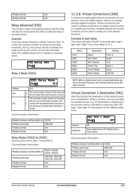
Fieldbus format<br />
Modbus format<br />
Relay Advanced [55D]<br />
This function makes it possible to ensure that the relay<br />
will also be closed when the VSD is malfunctioning or<br />
powered down.<br />
Example<br />
A process always requires a certain minimum flow. To<br />
control the required number of pumps by the relay<br />
mode NC, the e.g. the pumps can be controlled normally<br />
by the pump control, but are also activated<br />
when the variable speed drive is tripped or powered<br />
down.<br />
Relay 1 Mode [55D1]<br />
Default:<br />
N.O 0<br />
N.C 1<br />
N.O<br />
Communication information<br />
Relay Modes [55D2] to [55DC]<br />
Same function as for relay 1 mode [55D1].<br />
Communication information<br />
UInt<br />
UInt<br />
The normal open contact of the relay will<br />
be activated when the function is active.<br />
The normally closed contact of the relay<br />
will act as a normal open contact. The<br />
contact will be opened when function is<br />
not active and closed when function is<br />
active.<br />
Modbus Instance no/DeviceNet no: 43276<br />
Profibus slot/index 169/180<br />
Fieldbus format<br />
UInt<br />
Modbus format<br />
UInt<br />
Modbus Instance no/DeviceNet no:<br />
Profibus slot/index<br />
Fieldbus format<br />
Modbus format<br />
55D Relay Adv<br />
Stp A<br />
55D1 Relay Mode<br />
Stp A<br />
N.O<br />
43277–43278,<br />
43521–43529<br />
169/181–169/182,<br />
170/170–170/178<br />
UInt<br />
UInt<br />
11.5.6 Virtual Connections [560]<br />
Functions to enable eight internal connections of comparator,<br />
timer and digital signals, without occupying<br />
physical digital in/outputs. Virtual connections are<br />
used to wireless connection of a digital output function<br />
to a digital input function. Available signals and control<br />
functions can be used to create your own specific<br />
functions.<br />
Example of start delay<br />
The motor will start in RunR 10 seconds after DigIn1<br />
gets high. DigIn1 has a time delay of 10 s.<br />
Menu Parameter Setting<br />
[521] DigIn1 Timer 1<br />
[561] VIO 1 Dest RunR<br />
[562] VIO 1 Source T1Q<br />
[641] Timer1 Trig DigIn 1<br />
[642] Timer1 Mode Delay<br />
[643] Timer1 Delay 0:00:10<br />
NOTE: When a digital input and a virtual destination are<br />
set to the same function, this function will act as an OR<br />
logic function.<br />
Virtual Connection 1 Destination [561]<br />
With this function the destination of the virtual connection<br />
is established. When a function can be controlled<br />
by several sources, e.g. VC destination or Digital Input,<br />
the function will be controlled in conformity with “OR<br />
logic”. See DigIn for descriptions of the different selections.<br />
Default:<br />
Selection:<br />
Off<br />
Communication information<br />
Same selections as for Digital Input 1,<br />
menu [521].<br />
Modbus Instance no/DeviceNet no: 43281<br />
Profibus slot/index 169/185<br />
Fieldbus format<br />
Modbus format<br />
561 VIO 1 Dest<br />
Stp A<br />
Off<br />
UInt<br />
UInt<br />
Omron SX inverter manual Functional Description 129


