- Page 1 and 2: Cat. No. I127-EN-00B SX-V High powe
- Page 4 and 5: Safety Instructions Precautions sev
- Page 6 and 7: Precautions to be taken with a conn
- Page 8 and 9: Contents 1. Introduction ..........
- Page 10 and 11: 1. Introduction Omron SX-V is used
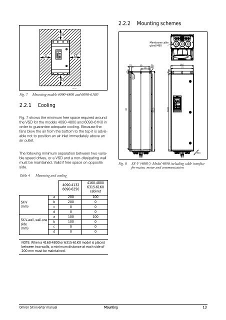
- Page 12 and 13: Category C2: Power Drive System (PD
- Page 14 and 15: 2. Mounting This chapter describes
- Page 18 and 19: 2330 2330 1000 600 1200 600 Fig. 11
- Page 20 and 21: 3. Installation The description of
- Page 22 and 23: RFI-Filter Mains VSD maintenance sw
- Page 24 and 25: 3.5.2 Tightening torque for mains a
- Page 26 and 27: 4. Getting Started This chapter is
- Page 28 and 29: 6. Set motor power [223]. 7. Set mo
- Page 30 and 31: 5. Control Connections 5.1 Control
- Page 32 and 33: 5.4 Connection example Fig. 24 give
- Page 34 and 35: angle. Do not let the signal cable
- Page 36 and 37: 6. Applications This chapter contai
- Page 38 and 39: 7. Main Features This chapter conta
- Page 40 and 41: One motor must stop before changing
- Page 42 and 43: Stop RunL RunR Enable Reset +24 V X
- Page 44 and 45: Torque [%] [4161] MaxAlarmMar (15%)
- Page 46 and 47: 7.6.2 Fixed MASTER This is the defa
- Page 48 and 49: 7.6.6 PID control When using the Pu
- Page 50 and 51: 7.6.8 Checklist And Tips 1. Main Fu
- Page 52 and 53: Stopping an additional pump This fi
- Page 54 and 55: 46 EMC and Machine Directive Omron
- Page 56 and 57: alarm messages. 300 Process Appl St
- Page 58 and 59: The VSD will be started and stopped
- Page 60 and 61: 100 0rpm Stp A 0.0A Menu 100 appear
- Page 62 and 63: Motor M2 44041-44048 172/180 to 174
- Page 64 and 65: Programming example: typedef struct
- Page 66 and 67:
58 Serial communication Omron SX in
- Page 68 and 69:
11.1.2 2nd Line [120] Sets the cont
- Page 70 and 71:
Local/Remote key function [217] The
- Page 72 and 73:
11.2.4 Motor Data [220] In this men
- Page 74 and 75:
When the motor has no cooling fan,
- Page 76 and 77:
PWM Mode [22E2] Default: Standard S
- Page 78 and 79:
Menu [234] PTC contains functions t
- Page 80 and 81:
The active set can be viewed with f
- Page 82 and 83:
Number of Trips [251] Any number se
- Page 84 and 85:
Communication information Modbus In
- Page 86 and 87:
Min Alarm [25K] Delay time starts c
- Page 88 and 89:
Modbus format UInt Brake Fault [25V
- Page 90 and 91:
Communication Fault Time [2642]] De
- Page 92 and 93:
Default: Speed F(AnIn) 0 Function o
- Page 94 and 95:
Fieldbus format Long, 1=0.001 Modbu
- Page 96 and 97:
pm 333 Acc MotPot Stp 16.0s A Nom.
- Page 98 and 99:
Deceleration Ramp Type [338] Sets t
- Page 100 and 101:
Default: Range: Depend on: 0 rpm -
- Page 102 and 103:
Fieldbus format Modbus format PID r
- Page 104 and 105:
Profibus slot/index 169/32 Fieldbus
- Page 106 and 107:
n [367] Preset Ref 6, with default
- Page 108 and 109:
PID sleep functionality This functi
- Page 110 and 111:
11.3.9 Pump/Fan Control [390] The P
- Page 112 and 113:
Change Timer [395] When the time se
- Page 114 and 115:
Lower Band Limit [39C] If the speed
- Page 116 and 117:
Run Times 1-6 [39H] to [39M] Unit:
- Page 118 and 119:
Max Alarm [416] Max Alarm Margin [4
- Page 120 and 121:
The default set levels for the (pre
- Page 122 and 123:
Overvolt control [424] Used to swit
- Page 124 and 125:
User Bipol mA 3 0-10V 4 2-10V 5 Use
- Page 126 and 127:
Communication information Modbus In
- Page 128 and 129:
Communication information Modbus In
- Page 130 and 131:
Profibus slot/index 169/145 Fieldbu
- Page 132 and 133:
AnOut1 Advanced [533] With the func
- Page 134 and 135:
Communication information Modbus In
- Page 136 and 137:
Digital Out 2 [542] Relay 2 [552] N
- Page 138 and 139:
Virtual Connection 1 Source [562] W
- Page 140 and 141:
Communication information No. 1 2 3
- Page 142 and 143:
Communication information Modbus In
- Page 144 and 145:
Y Operator 2 [624] Selects the seco
- Page 146 and 147:
Timer 1 Mode [642] Default: Off 0 D
- Page 148 and 149:
Timer 2 T2 [655] Default: 0:00:00,
- Page 150 and 151:
DC Link Voltage [719] Displays the
- Page 152 and 153:
The example in Fig. 94 indicates th
- Page 154 and 155:
Energy [733] Displays the total ene
- Page 156 and 157:
Communication information Modbus In
- Page 158 and 159:
150 Functional Description Omron SX
- Page 160 and 161:
152 Functional Description Omron SX
- Page 162 and 163:
154 Functional Description Omron SX
- Page 164 and 165:
156 Functional Description Omron SX
- Page 166 and 167:
12.2 Trip conditions, causes and re
- Page 168 and 169:
Table 28 Trip condition, their poss
- Page 170 and 171:
Check external wiring, connections
- Page 172 and 173:
Table 30 Brake resistor SX-V 400V t
- Page 174 and 175:
When the "Safe Stop" condition is a
- Page 176 and 177:
168 Options Omron SX inverter manua
- Page 178 and 179:
Table 35 Typical motor power at mai
- Page 180 and 181:
14.3 Operation at higher temperatur
- Page 182 and 183:
14.6 Environmental conditions Table
- Page 184 and 185:
176 Technical Data Omron SX inverte
- Page 186 and 187:
Table 46 Type cables cross-sections
- Page 188 and 189:
180 Technical Data Omron SX inverte
- Page 190 and 191:
DEFAULT CUSTOM DEFAULT CUSTOM 2651
- Page 192 and 193:
DEFAULT CUSTOM DEFAULT CUSTOM 5197
- Page 194 and 195:
DEFAULT CUSTOM DEFAULT CUSTOM 81I I
- Page 196 and 197:
89E DEFAULT DigOut status 89F AnIn
- Page 198 and 199:
External Control Panel ............
- Page 200 and 201:
(413) .............................
- Page 202:
T Terminal connections ............