AC Variable Speed Drive Installation & Operating Instructions
Optidrive P2 User Guide
Optidrive P2 User Guide
- No tags were found...

Create successful ePaper yourself
Turn your PDF publications into a flip-book with our unique Google optimized e-Paper software.
8. Extended Parameters<br />
Optidrive ODP-2 User Guide Revision 1.01<br />
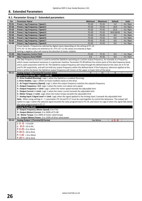
8.1. Parameter Group 2 - Extended parameters<br />
Par Parameter Name Minimum Maximum Default Units<br />
P2-01 Preset / Jog Frequency / <strong>Speed</strong> 1 P1-02 P1-01 5.0 Hz / Rpm<br />
P2-02 Preset / Jog Frequency / <strong>Speed</strong> 2 P1-02 P1-01 10.0 Hz / Rpm<br />
P2-03 Preset / Jog Frequency / <strong>Speed</strong> 3 P1-02 P1-01 25.0 Hz / Rpm<br />
P2-04 Preset / Jog Frequency / <strong>Speed</strong> 4 P1-02 P1-01 50.0 (60.0) Hz / Rpm<br />
P2-05 Preset / Jog Frequency / <strong>Speed</strong> 5 P1-02 P1-01 0.0 Hz / Rpm<br />
P2-06 Preset / Jog Frequency / <strong>Speed</strong> 6 P1-02 P1-01 0.0 Hz / Rpm<br />
P2-07 Preset / Jog Frequency / <strong>Speed</strong> 7 P1-02 P1-01 0.0 Hz / Rpm<br />
P2-08 Preset / Jog Frequency / <strong>Speed</strong> 8 P1-02 P1-01 0.0 Hz / Rpm<br />
Preset <strong>Speed</strong>s / Frequencies selected by digital inputs depending on the setting of P1-13.<br />
If P1-10 = 0, the values are entered as Hz. If P1-10 > 0, the values are entered as Rpm.<br />
Setting a negative value will reverse the direction of motor rotation.<br />
P2-09 Skip Frequency Centre Point P1-02 P1-01 0.0 Hz / Rpm<br />
P2-10 Skip Frequency Band Width 0.0 P1-01 0.0 Hz / Rpm<br />
The Skip Frequency function is used to avoid the Optidrive operating at a certain output frequency, for example at a frequency<br />
which causes mechanical resonance in a particular machine. Parameter P2-09 defines the centre point of the skip frequency band,<br />
and is used conjunction with P2-10. The Optidrive output frequency will ramp through the defined band at the rates set in P1-03<br />
and P1-04 respectively, and will not hold any output frequency within the defined band. If the frequency reference applied to the<br />
drive is within the band, the Optidrive output frequency will remain at the upper or lower limit of the band.<br />
P2-11 Analog Output 1 (Terminal 8) Function Select 0 11 8 -<br />
Digital Output Mode. Logic 1 = +24V DC<br />
0 : <strong>Drive</strong> Enabled (Running). Logic 1 when the Optidrive is enabled (Running)<br />
1: <strong>Drive</strong> Healthy. Logic 1 When no Fault condition exists on the drive<br />
2 : At Target Frequency (<strong>Speed</strong>). Logic 1 when the output frequency matches the setpoint frequency<br />
3 : Output Frequency > 0.0. Logic 1 when the motor runs above zero speed<br />
4 : Output Frequency >= Limit. Logic 1 when the motor speed exceeds the adjustable limit<br />
5 : Output Current >= Limit. Logic 1 when the motor current exceeds the adjustable limit<br />
6 : Motor Torque >= Limit. Logic when the motor torque exceeds the adjustable limit<br />
7 : Analog Input 2 Signal Level >= Limit. Logic when the signal applied to the Analog Input 2 exceeds the adjustable limit<br />
Note : When using settings 4 – 7, parameters P2-16 and P2-17 must be used together to control the behaviour. The output will<br />
switch to Logic 1 when the selected signal exceeds the value programmed in P2-16, and return to Logic 0 when the signal falls below<br />
the value programmed in P2-17.<br />
Analog Output Mode<br />
8 : Output Frequency (Motor <strong>Speed</strong>). 0 to P-01<br />
9 : Output (Motor) Current. 0 to 200% of P1-08<br />
10 : Motor Torque. 0 to 200% of motor rated torque<br />
11 : Output (Motor) Power. 0 to 150% of drive rated power<br />
P2-12 Analog Output 1 (Terminal 8) Format See Below -<br />
= 0 to10V.<br />
= 10 to 0V,<br />
= 0 to 20mA<br />
= 20 to 0mA<br />
= 4 to 20mA<br />
= 20 to 4mA<br />
26<br />
www.invertek.co.uk