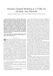
FPGA-based time counters with a wander measurement mode
FPGA-based time counters with a wander measurement mode
FPGA-based time counters with a wander measurement mode

Create successful ePaper yourself
Turn your PDF publications into a flip-book with our unique Google optimized e-Paper software.
<strong>FPGA</strong>-<strong>based</strong> <strong>time</strong> <strong>counters</strong><br />
<strong>with</strong> a <strong>wander</strong> <strong>measurement</strong> <strong>mode</strong><br />
2012<br />
R. Szplet, P. Kwiatkowski, Z. Jachna, K. Rozyc<br />
Department of Electronics<br />
Military University of Technology<br />
Warsaw, Poland<br />
rszplet@wat.edu.pl<br />
Abstract – This paper presents the design and basic technical<br />
features of the series of virtual <strong>time</strong> interval <strong>counters</strong> <strong>with</strong> a <strong>wander</strong><br />
<strong>measurement</strong> <strong>mode</strong>. The <strong>counters</strong> are developed as computer card<br />
<strong>with</strong> PCI interface and as portable modules <strong>with</strong> USB or Wi-Fi<br />
interfaces. The <strong>measurement</strong> functions are executed by the <strong>time</strong><br />
counter unit integrated in an <strong>FPGA</strong> device. To achieve high<br />
precision and wide <strong>measurement</strong> <strong>mode</strong> a two-stage interpolation<br />
method is used. The precise and fast <strong>time</strong>-to-digital (T/D)<br />
conversion in the second stage of interpolation is performed <strong>with</strong><br />
the aid of carry chains built-in the <strong>FPGA</strong> chip. The use of up to 16<br />
such chains in a single interpolator leads to the high <strong>measurement</strong><br />
resolution of 1.2 ps. The short death <strong>time</strong> of T/D converters allowed<br />
to introduce several specialized <strong>measurement</strong> <strong>mode</strong>s, and among<br />
them the <strong>wander</strong> <strong>measurement</strong>.<br />
Keywords—<strong>time</strong> interval counter, two-stage interpolation,<br />
<strong>wander</strong> <strong>measurement</strong><br />
I. INTRODUCTION<br />
The <strong>mode</strong>rn microelectronic technology allows to develop<br />
of high-precision, low-cost <strong>time</strong> interval counter as a single<br />
<strong>FPGA</strong> (Field Programmable Gate Array) device [1–5].<br />
Typically in such a <strong>time</strong> counter a tapped delay line is used for<br />
T/D conversion. Thus the resolution of conversion is limited<br />
by the propagation <strong>time</strong> of a single delay element. To increase<br />
the resolution two shifted delay lines [6] or independent delay<br />
lines [7] may be used. The highest resolution and precision are<br />
provided in <strong>time</strong> <strong>counters</strong> combining the two-stage<br />
interpolation and multiple independent delay lines [8]. To make<br />
such integrated <strong>counters</strong> easy applicable and more useful for<br />
average user we considered their possible applications and<br />
designed three <strong>mode</strong>ls of virtual <strong>time</strong> <strong>counters</strong> in the forms of<br />
a computer card and small portable modules. They differ each<br />
other mainly <strong>with</strong> respect to the computer interface. The<br />
computer card is equipped <strong>with</strong> the PCI interface, while<br />
portable modules have USB or Wi-Fi interface.<br />
Precise <strong>time</strong> interval <strong>measurement</strong>s are crucial in many<br />
areas of research and industry. In telecommunication, slow<br />
variations in signal timing through a system (<strong>wander</strong>) are<br />
investigated [9–12]. Due to these needs we introduced the<br />
specialized operation <strong>mode</strong>s of the counter, including<br />
<strong>measurement</strong> of Time-Interval Error (TIE) and Time<br />
Deviation (TDEV). Each developed counter is controlled by a<br />
user-friendly software working in the Windows environment<br />
and creating a virtual front-panel of the counter on the monitor<br />
screen.<br />
In this paper we describe the design of the integrated<br />
counter chip, its operation in the <strong>wander</strong> <strong>measurement</strong> <strong>mode</strong><br />
and the respective technical details. We also present the results<br />
of some performed tests.<br />
II. INTERPOLATION METHOD<br />
The wide <strong>measurement</strong> range and high resolution in the<br />
advanced integrated <strong>time</strong> <strong>counters</strong> are obtained by the use of<br />
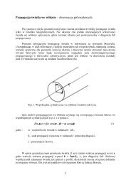
two-stage interpolation method (fig. 1). The wide range of the<br />
measured <strong>time</strong> intervals T is achieved by counting an integer<br />
number N of the reference clock periods T 0 , whose leading<br />
pulse edges appear at the counter inputs between the leading<br />
edges of the START and STOP pulses. These pulses represent,<br />
respectively, the begin and end of the measured <strong>time</strong> interval<br />
T. Then the product NT 0 is calculated giving a rough estimate<br />
of the T. The higher resolution is provided by two two-stage<br />
interpolators, one on each input channel, which precisely<br />
measure the fractional parts of T <strong>with</strong>in single clock periods.<br />
In the First Interpolation Stage (FIS) of each interpolator a<br />
multiphase clock is commonly used. In our case we applied<br />
Four Phase Clock (FPC). The FIS detects in which segment of<br />
FPC the input pulse START (STOP) appears that allows to<br />
evaluate of T ST1 (T SP1 ). Simultaneously, the <strong>time</strong> interval T ST2<br />
(T SP2 ) between the START (STOP) pulse and the nearest edge<br />
of the FPC is measured in the Second Interpolation Stage<br />
(SIS). The final <strong>measurement</strong> result is calculated as:<br />
T = NT + T + T ) − ( T + T ) (1)<br />
0 ( ST1<br />
ST 2 SP1<br />
SP2<br />
Figure 1. Two-stage interpolation method<br />
This work was supported by the Polish National Science Centre under<br />
contract no. DEC-2011/01/B/ST7/03278
III.<br />
TIME COUNTER<br />
The block diagram of <strong>time</strong> counter <strong>based</strong> on the two-stage<br />
interpolation method is shown in figure 2. The FIS detects the<br />
FPC segment in which an input pulse (START or STOP)<br />
appears and synchronizes the latter <strong>with</strong> the nearest FPC edge.<br />
This edge is then used both to enable the main counter and for<br />
precise conversion in the SIS. A synchronizer is needed to<br />
ensure proper work of the main counter. The results from FIS<br />
and SIS are converted to NB code and then they are<br />
transferred to the code processor. This processor executes the<br />
statistical code density test [13], performed for identification<br />
of the nonlinearity of interpolator, calculates and stores the<br />
resulting transfer characteristic. The <strong>measurement</strong> results from<br />
interpolator are calculated and corrected on-the-fly in that<br />
block as well.<br />
To obtain high <strong>measurement</strong> rate and minimize the dead<br />
<strong>time</strong> between successive <strong>measurement</strong>s a FIFO memory in the<br />
<strong>FPGA</strong> device is used. It allows increasing the maximum<br />
<strong>measurement</strong> rate up to 5 million <strong>measurement</strong>s per second<br />
(when measuring the “zero <strong>time</strong> interval”).<br />
Figure 3. External view of the counter board <strong>with</strong> PCI interface and<br />
the counter module <strong>with</strong> USB nterface<br />
IV. MEASUREMENT MODES<br />
The counter can operate either in the calibration <strong>mode</strong> or<br />
in the <strong>measurement</strong> <strong>mode</strong>s. The calibration is performed<br />
automatically in two consecutive procedures. In the first one,<br />
the transfer characteristics of interpolators are identified. In<br />
the second one, the <strong>time</strong> offset between two input channels<br />
(START and STOP) is calculated.<br />
Each of five <strong>measurement</strong> <strong>mode</strong>s may be selected by<br />
clicking the predefined virtual keys on the virtual front panel<br />
of the counter (fig. 4).<br />
Figure 2. Block diagram of the <strong>time</strong> counter<br />
A simple FPC generator can be built as a tapped delay line.<br />
Such line consists of few logic gates, which have appropriate<br />
delays to obtain required clock phase segments. As the paths<br />
delays are crucial to achieve high uniformity of the clock<br />
segments, the manual routing is needed.<br />
For precise T/D conversion <strong>with</strong>in a single phase segment<br />
of the FPC, tapped delay line is used. It consists of<br />
multiplexers forming the fast carry chains in <strong>FPGA</strong> devices.<br />
Such multiplexers offer the shortest propagation <strong>time</strong> among<br />
all logical elements available in programmable devices. Due to<br />
recent improvement in CMOS technology the delay of a single<br />
multiplexer improved from tens of picoseconds (45 ps –<br />
Spartan-3) to several picoseconds (19 ps – Spartan-6). To<br />
further improve the delay line resolution beyond its cell delay<br />
we proposed to use multiple independent delay lines for<br />
creating an equivalent coding line [7, 8]. In this way the n-<br />
delay lines increase the resolution of about n-<strong>time</strong>s.<br />
Figure 3 shows the external view of the computer card<br />
(left) and the portable module (right). The <strong>FPGA</strong> counter is<br />
located in the center of the card (yellow label) and below is<br />
the PCI interface chip.<br />
Figure 4. Example of the virtual front panel of the counter operating<br />
in the Time Interval <strong>mode</strong><br />
The fundamental <strong>measurement</strong> <strong>mode</strong> is the Time Interval,<br />
which allows to measure of intervals <strong>with</strong> the resolution up to<br />
1.2 ps and precision below 10 ps. The thresholds of the input<br />
comparators can be set manually in the range –4V to 4V, or<br />
can be preset on the fixed (TTL or CMOS) level. The<br />
threshold level can also be adjusted automatically.<br />
The Pulse Width <strong>mode</strong> allows for <strong>measurement</strong> of the<br />
width of pulses applied to the input START or STOP. The<br />
polarity of pulses (active edges) and threshold level are<br />
defined in the same way as in the Time Interval <strong>mode</strong>.
In the Frequency <strong>mode</strong>, the signal frequency up to 3.5<br />
GHz is measured <strong>with</strong> the use of the reciprocal method by<br />
measuring the <strong>time</strong> interval consisting of a known integer<br />
number of signal periods, calculating the duration of a single<br />
period, and calculating its reciprocal.<br />
In the Period <strong>mode</strong> the <strong>measurement</strong>s are performed in a<br />
similar way as in the Frequency <strong>mode</strong>.<br />
In the Totalize <strong>mode</strong> the input pulses are counted <strong>with</strong>in a<br />
preset <strong>time</strong> gate. The duration of the gate may be selected<br />
from 1 s to 10 s, or not set (Open Gate <strong>mode</strong>). For each gate<br />
the number of counted pulses and the respective mean<br />
frequency in pulses per second are displayed.<br />
V. WANDER MEASUREMENT<br />
A commonly used parameter for characterizing the <strong>wander</strong><br />
is the Time Interval Error (TIE) [11]. The maximum value of<br />
TIE (MTIE), computed from an array of TIE data, can<br />
characterize the frequency offsets and phase transients of a<br />
tested signal to obtain a clear view of quality of relevant<br />
electronic apparatus or systems. The <strong>time</strong> interval <strong>counters</strong><br />
offer possibility of precise <strong>measurement</strong> of TIE, MTIE and<br />
Time Deviation (TDEV) related to <strong>wander</strong>.<br />
The <strong>time</strong> error function TE(t) of a clock (in standards also<br />
x(t)), <strong>with</strong> respect to a frequency standard, is the difference<br />
between the <strong>time</strong> of that clock and the reference <strong>time</strong><br />
x(t) TE(t) = T(t) – T ref (t).<br />
Referring to figure 5, the sampling interval 0 is specified<br />
as follows. It begins <strong>with</strong> the START ENABLE signal<br />
generated to allow <strong>measurement</strong> of the first TE (marked by<br />
TE 1 ) between the nearest zero-crossing of the tested signal (of<br />
frequency f t ) and that of the reference signal (of frequency f r ).<br />
Since the interval 0 is generated by the counter<br />
asynchronously <strong>with</strong> reference to the tested signal, the <strong>time</strong><br />
lag from beginning of the sampling interval to the START<br />
moment (t 1 ) is randomly variable <strong>with</strong>in the range (0 – 1)T t .<br />
That <strong>measurement</strong> is repeated in the end of the interval 0 and<br />
the second TE equal to the delay TE 2 is measured.<br />
The TIE sample is defined over the sampling interval 0 as the<br />
difference TE 2 – TE 1 measured in both ends of the<br />
synchronized sampling interval 0s = t 2 – t 1 . The worst-case<br />
difference between the interval 0 and 0s is ±T t .<br />
We can observe a train of ‘TE samples’ (TE 1 , TE 2 ,...) and a<br />
train of ‘TIE samples’ of the form<br />
TIE 1 ( 0 ) = TE(t 2 ) – TE(t 1 ) = TE 2 – TE 1<br />
TIE 2 ( 0 ) = TE(t 3 ) – TE(t 2 ) = TE 3 – TE 2<br />
.............<br />
The result of TIE <strong>measurement</strong> over the observation<br />
interval is the root-mean-square value TIE rms () calculated<br />
from a finite number N of TE samples collected <strong>with</strong>in that<br />
interval. Utilizing the number n = N – 1 of the TIE( 0 ) samples<br />
TIE rms ( 0 ,) =<br />
n<br />
1<br />
(TIE i<br />
)<br />
n =<br />
This is shown on the display panel (fig. 6) after collecting<br />
data for a specified observation interval. The maximum <strong>time</strong><br />
interval error (MTIE) is defined as the maximum peak-to-peak<br />
variation of TE in the all possible observation intervals = n 0<br />
<strong>with</strong>in a <strong>measurement</strong> period T. The array of N samples of TE<br />
(collected <strong>with</strong>in an observation interval of = n 0 ) may be<br />
searched by software to find the minimum value TE min and the<br />
maximum value TE max . Then MTIE( 0 ,) = TE max – TE min .<br />
i 1<br />
2<br />
Figure 6. Virtual front panel of the counter operating in the TIE <strong>mode</strong><br />
Figure 5. Measurement of Time Interval Error<br />
In many telecommunication applications, following the ITU<br />
Recommendations there is a need to check if the <strong>measurement</strong><br />
data conform to the requirements specified in a relevant ITU<br />
document. In such a case a relevant limit mask can also be<br />
displayed. An example is shown in fig. 7, where the mask<br />
defined in the ITU Recommendation G812 (clock 1) is<br />
displayed. It allows for easy checking the quality of the clock<br />
under test.In accordance <strong>with</strong> ITU-T Recs G.813 and G.812<br />
the maximum sampling interval is limited to 0max = 1/30 s <br />
33 ms. The <strong>counters</strong> provide the 0 magnitude selectable in 1-<br />
2-5-10-20-33ms sequence.
the uncertainty was diminished below 35 ps. The newest<br />
counter <strong>with</strong> 16 delay lines in SIS (T4100U), implemented in<br />
45 nm CMOS technology (Spartan-6), allows to achieve the<br />
precision better than 10 ps <strong>with</strong>in the range of 100 ms. The<br />
latter results are much lower than derived from popular and<br />
commonly used <strong>counters</strong> such as HP53132 (Hewlett Packard)<br />
and SR620 (Stanford Research Systems).<br />
Figure 7. Graph MTIE() <strong>with</strong> limit mask (G.812 clock 1)<br />
VII. CONCLUSIONS<br />
The described <strong>time</strong> <strong>counters</strong> allow precise <strong>measurement</strong>s<br />
of long <strong>time</strong> intervals <strong>with</strong> picosecond accuracy at a lower<br />
price than standalone <strong>counters</strong> of comparable parameters. The<br />
natural applications of the <strong>counters</strong> are advanced systems for<br />
<strong>time</strong> keeping, laser ranging and navigation. They can also be<br />
used in industrial and research laboratories, and in ATE<br />
systems. Thanks to the use of programmable devices (<strong>FPGA</strong><br />
and CPLD) the counter boards can be customized to match the<br />
user applications.<br />
VI.<br />
EXAMPLE TEST RESULTS<br />
The <strong>measurement</strong> uncertainty of the successive generations<br />
of our <strong>time</strong> counter is shown in figure 8. As a reference signal<br />
of 10 MHz we used rubidium frequency standard FS725<br />
(Stanford Research Systems). As sources of <strong>time</strong> intervals we<br />
used in turn three delay generators: GFT1004 (Greenfield<br />
Technology) for the range 10 ns – 200 ns, 81130A (Hewlett<br />
Packard) for the range 500 ns – 5 s and T5300U (Vigo<br />
System) for the <strong>time</strong> intervals longer than 10 s. The use of<br />
three generators allowed to select their best operation ranges<br />
(the lowest jitter) for delay generation.<br />
The <strong>time</strong> counter <strong>with</strong> a single tapped delay line in SIS<br />
(T2700U), implemented in 90 nm CMOS technology<br />
(Spartan-3), provides <strong>measurement</strong> uncertainty below 50 ps.<br />
By the use of the equivalent coding line composed of two<br />
delay lines implemented in the same technology (T3200U)<br />
Figure 8. Comparison of the precision (standard <strong>measurement</strong> uncertainty) of<br />
succesisive versions of our <strong>time</strong> counter (T2700U <strong>with</strong> a single coding line,<br />
T3200U <strong>with</strong> a double coding line and T4100U <strong>with</strong> multiple coding lines)<br />
and selected commercial <strong>time</strong> <strong>counters</strong> (HP53132A, Hewlett-Packard and<br />
SR620, Stanford Research Systems)<br />
REFERENCES<br />
[1] R. Szplet, J. Kalisz, R. Szymanowski, Interpolating Time Counter <strong>with</strong><br />
100-ps Resolution on a Single <strong>FPGA</strong> Device, IEEE Transactions on<br />
Instrumentation and Measurement, vol. 49, no. 4, 2000, pp. 879-883.<br />
[2] J. Wu, Z. Shi, I. Y. Wang, Firmware-only Implementation of Time-to-<br />
Digital Converter (TDC) in Field-Programmable Gate Array (<strong>FPGA</strong>),<br />
IEEE 2003 Nuclear Science Symposium Conference Record, Portland,<br />
Oregon, USA, pp. 177-181 Vol. 1<br />
[3] J. Song, Q. An, S. Liu, A High-resolution Time-to-Digital converter<br />
Implemented in Field-Programmable-Gate-Arrays, IEEE Transactions<br />
on Nuclear Science, vol. 53, no. 1, 2006, pp. 236-241<br />
[4] R. Szplet, J. Kalisz, Z. Jachna, A 45 ps <strong>time</strong> digitizer <strong>with</strong> two-phase<br />
clock and dual-edge two-stage interpolation in Field Programmable<br />
Gate Array device, Measurement Science and Technology, vol. 20<br />
(2009) 025108, pp. 11<br />
[5] M. Daigneault, J. David, A Novel 10 ps Resolution TDC Architecture<br />
Implemented in a 130nm Process <strong>FPGA</strong>, 8th IEEE Int. NEWCAS<br />
Conference, 2010, pp. 281-284<br />
[6] M. Zieliski, D. Chaberski, M. Kowalski, R. Frankowski, S. Grzelak,<br />
High-resolution <strong>time</strong>-interval measuring system implemented in single<br />
<strong>FPGA</strong> device, Measurement vol. 35, 2004, pp. 311-317<br />
[7] R. Szplet, Z. Jachna, J. Kalisz, A Flash Time-to-Digital Converter <strong>with</strong><br />
Two Independent Time Coding Lines, IEEE 2011 ADC Forum, Orvieto,<br />
Italy, 2011, 6 pp.<br />
[8] R. Szplet, Z. Jachna, P Kwiatkowski, K Rozyc, A 1.2 ps resolution<br />
interpolating <strong>time</strong> counter <strong>based</strong> on multiple independent coding lines,<br />
Sent for publication in Measurement Science and Technology<br />
[9] A. Dobrogowski, M. Kasznia, Time Effective Methods of Calculation of<br />
Maximum Time Interval Error, IEEE Trans. Instr. Meas., vol. 50, no. 3,<br />
2001, pp. 732-741.<br />
[10] S. Bregni, Synchronization of Digital Telecommunications Networks, J.<br />
Wiley, London, 2002.<br />
[11] A. Dobrogowski, Sygnał czasu, Wyd. Politechniki Poznaskiej, 2003<br />
[12] A. Dobrogowski, M. Kasznia, Real-Time MTIE Assessment <strong>with</strong><br />
Flexible Control of Computation Process, Proc. IEEE Int. Frequency<br />
Control Symposium, 2009, pp. 1102–1107<br />
[13] S. Cova, M. Bertolaccini, “Differential linearity testing and precision<br />
calibration of multichannel <strong>time</strong> sorters”, Nuclear Instruments and<br />
Methods, vol. 77, no. 2, 1970, pp. 269–276

![1RUPDOQH \FLHFKU]H FLMD VNLH](https://img.yumpu.com/54031532/1/184x260/1rupdoqh-flhfkuh-flmd-vnlh.jpg?quality=85)