computing - Fischertechnik
computing - Fischertechnik
computing - Fischertechnik

Create successful ePaper yourself
Turn your PDF publications into a flip-book with our unique Google optimized e-Paper software.
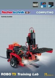
COMPUTING<br />
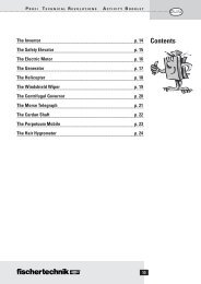
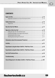
Contents<br />
2<br />
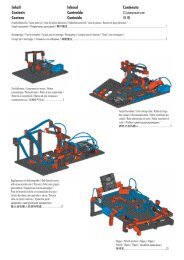
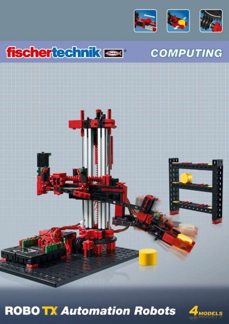
ROBO TX Automation Robots<br />
Welcome to the fischertechnik Computing World 3<br />
About this Activity Booklet 3<br />
Industrial robots 4<br />
Component Explanations 5<br />
The Construction Set Contains All of This 5<br />
Actuators 5<br />
Encoder Motors 5<br />
XS motors 5<br />
Sensors 6<br />
Pushbutton switches 6<br />
As a "closer" (normally open switch) 6<br />
As a "break contact" (normally closed switch) 6<br />
ROBO TX Controller 6<br />
ROBO Pro Software 7<br />
Gripper robot 8<br />
Robot coordinate system 8<br />
High bay storage rack 10<br />
Pivoting gripper 12<br />
3-axis robot 14<br />
Teach-in procedure 14<br />
Quick programming for 3-axis robot 15<br />
Load, start, select control panel 15<br />
Keys on control panel 15<br />
Stop 16<br />
Save 16<br />
Towers of Hanoi 17<br />
Loading teach-in sequence on TX controller 17
COMPUTING<br />
Welcome to the fischertechnik Computing World<br />
Hello!<br />
Congratulations on your purchase of the ROBO TX Automation Robot set<br />
from fischertechnik. We promise you that your interest will be rewarded.<br />
This is because with this construction set you can conduct a lot of interesting<br />
experiments and solve exciting tasks.<br />
3<br />
ROBO TX Automation Robots<br />
Reading through this monitor booklet and trying out the experiments and assignments will teach<br />
you step for step how various industrial robots can be controlled and programmed with th ROBO TX<br />
Controller from fischertechnik.<br />
This is the way learning works; you can't start immediately with the most difficult things even if they are<br />
often a little bit more interesting than the somewhat more simple ones. This is why we have structured<br />
the experiments and tasks in this booklet so that you learn something different with every new task and<br />
can then use this for the next task.<br />
So don't hesitate, simply get started and together we will then proceed to the more comprehensive<br />
assignments.<br />
Now we wish you a great deal of fun and success experimenting with the ROBO TX automation robot set.<br />
Your team from<br />
About this Activity Booklet<br />
For testing only.rpp<br />
This PDF Activity booklet has a few features not present in the printed booklet. Most are similar to those<br />
you may already be familiar with from the Internet. But sometimes they can also do more.<br />
▯<br />
▯<br />
Purple text<br />
This shows you information on the term itself when you roll over it with the mouse.<br />
Underlined blue text<br />
This actuates a function when clicked - for example starting the ROBO Pro help.<br />
▯ ROBO Pro Symbol<br />
This is always located in the vicinity of assignments. This makes sense, because as soon as you click on it a<br />
suitable example program opens with a possible solution.<br />
All example programs are listed under C:\Program Files\ROBOPro\Sample Programs\ROBO TX Automation<br />
Robots.
COMPUTING<br />
Industrial robots<br />
An industrial robot is a machine with a universal, freely programmable<br />
motion sequence with the purpose of performing highly varying tasks.<br />
It can be used for handling, assembling or processing workpieces.<br />
Frequently industrial robots are equipped with a gripper to hold workpieces.<br />
However other tools can also be integrated to perform certain<br />
types of work. As the name says, Industrial robots are used for applications<br />
in industry (e.g. production of automobiles). As soon as a robot<br />
has been programmed for a task, it can perform the work by itself<br />
without manual control.<br />
Areas of application<br />
4<br />
ROBO TX Automation Robots<br />
The inventor of the industrial robot is considered to be George Devol, who<br />
registered a patent in the USA in 1954 for a programmable manipulator.<br />
Together with Joseph F. Engelberger, Devot founded the world's first robot<br />
company, Unimation.<br />
Industrial robots are used in many areas of production for work as:<br />
▯ Welding robots<br />
▯ Cutting robots<br />
▯ Measuring robots<br />
▯ Paining robots<br />
▯ Grinding robots<br />
▯ Handling equipment for:<br />
Palleting<br />
Stacking<br />
Packaging<br />
Assembling<br />
Equipping machines<br />
Removing parts
COMPUTING<br />
Component Explanations<br />
The Construction Set Contains All of This<br />
Actuators<br />
5<br />
ROBO TX Automation Robots<br />
The set contains numerous fischertechnik modules, various motors, pushbuttons and colored assembly<br />
instructions for building various models.<br />
After you have unpacked all the modules, it is first necessary to install some components before starting<br />
(e.g. cables and plugs). The exact ones are described in the assembly instructions under "Assembly Tips."<br />
It is best to do this first.<br />
Actuators are all components, which can perform an action. This means when they are connected to an<br />
electric current, they become "active" in some form. Usually you can see this directly, e.g. a motor starts<br />
turning.<br />
Encoder Motors<br />
At first glance, these are normal electric motors, which are designed for a voltage of nine volts and current<br />
input of a maximum of 0.5 amperes.<br />
However, the encoder motors can do even more than this: In addition to the connection for the power<br />
supply for the motor, they have another jack socket for a three-pin connection cable and through this and<br />
with the aid of what is called the encoder, the rotational movement of the motor can be evaluated.<br />
The encoders on the fischertechnik encoder motors generate three pulses with each revolution of the<br />
motor shaft. And because the encoder motors also have a gearbox with a transmission ratio of 25:1<br />
(meaning "25 to 1"), then one revolution of the shaft, which comes out of the gearbox, corresponds to<br />
75 pulses of the encoder.<br />
The encoder motors are connected to outputs M1 to M4 on the ROBO TX Controller. The encoder signals<br />
are read in over inputs C1 to C4.<br />
XS motors<br />
The XS motor is an electric motor, which is exactly as long and high as a fischertechnik building block.<br />
In addition, it is very light. This allows it to be installed at locations where there is insufficient space for<br />
larger motors. The XS motor is designed for a voltage of nine volts and current input of a maximum of<br />
0.3 amperes.<br />
This is also connected to the outputs M1 to M4 on the ROBO TX Controller.
COMPUTING<br />
Sensors<br />
6<br />
ROBO TX Automation Robots<br />
Sensors are so to speak the counterpart to the actuators. This is because they do not perform any actions,<br />
but react to certain situations and events.<br />
Pushbutton switches<br />
The pushbutton is also called a touch sensor. When the red button is pressed a switch is switched mechanically<br />
allowing current to flow from contact 1 (middle contact) to contact 3. Simultaneously the contact<br />
between connections 1 and 2 is interrupted. So you can use the pushbutton in two different ways:<br />
As a "closer" (normally open switch):<br />
Contacts 1 and 3 are connected.<br />
Pushbutton switch is pressed: Electricity flows.<br />
Pushbutton switch is not pressed: No electricity flows.<br />
As a "break contact" (normally closed switch):<br />
Contacts 1 and 2 are connected.<br />
Pushbutton switch is pressed: No electricity flows.<br />
Pushbutton switch is not pressed: Electricity flows.<br />
ROBO TX Controller<br />
The sensors are connected to the universal inputs I1 to I8 on the ROBO TX Controller.<br />
The ROBO TX Controller is the most important component in the robot model.<br />
It controls the actuators and evaluated information from the sensors. For this<br />
purpose the ROBO TX Controller has numerous connections for connection<br />
to the components. What components can be connected to what connections<br />
and what the functions of the connections are are described in the<br />
instruction manual for the ROBO TX Controller.<br />
A special treat is the integrated Bluetooth interface. It allows you to connect your PC<br />
to the ROBO TX Controller. Or to connect a number of controllers with one another. You can define how<br />
the controller interacts with the individual components and what they are to do in detail in the program<br />
you write with the ROBO Pro software.<br />
3<br />
2<br />
3<br />
2<br />
1<br />
1
COMPUTING<br />
ROBO Pro Software<br />
ROBO Pro is a graphical programming surface which allows you to create<br />
programs for the ROBO TX Controller.<br />
"Graphical programming surface" means that you don't have to "write" the<br />
programs by hand line for line; you can put it together simply with the aid<br />
of graphic images. An example of this type of program is shown in the<br />
figure at the left.<br />
7<br />
ROBO TX Automation Robots<br />
The exact procedure for creating such a program is described in detail in the ROBO Pro Help in Chapters<br />
3 and 4. It is best to first read through these chapters in ROBO Pro Help. This will allow you to learn a<br />
little about the software, so that you can then start experimenting immediately.<br />
You need the ROBO Pro version 3.1 or higher for the ROBO TX Automation Robot set. If you have an<br />
older version of the software, it will be automatically updated when you install the ROBO TX Automation<br />
Robot CD.<br />
A Few Tips<br />
Experimenting is most enjoyable when the experiments really work. For this reason it is necessary to<br />
observe a few basic rules:<br />
▯ Work carefully.<br />
Take your time and look precisely at the assembly instructions for the model. If you have to look for an<br />
error later then this will take much longer.<br />
▯ Check the movement of all parts.<br />
When putting models together continually check to see if the parts, which are to move, move easily.<br />
▯ Use the Interface test<br />
Before starting to write a program for a model, you should test all of the parts connected to the ROBO<br />
TX Controller using the ROBO Pro interface test. How you use these is described in the ROBO Pro<br />
Help in chapter 2.4.
COMPUTING<br />
Gripper robot<br />
For your first experiment you can build the "Gripper robot"<br />
model using the assembly instructions and wire the electrical<br />
elements.<br />
The robot can turn and raise and lower its arm.<br />
These are known as the motion axes of a robot.<br />
Robot coordinate system<br />
Gripper robot_1.rpp<br />
8<br />
ROBO TX Automation Robots<br />
It is necessary to specify the position of each individual linear axis and the rotary axis of the robot. This<br />
then defines the position of the gripper.<br />
The zero position for each axis and the gripper is defined by a limit switch.<br />
Positioning is accomplished by counting the pulses in the encoder motor or on the mechanical pulse sensor.<br />
The table below provides an overview of the various axes on your model:<br />
Action Axis Motor Limit switch<br />
Pulse sensor/<br />
encoder<br />
Turning X M1 I1 C1<br />
Raising/Lowering Z M3 I3 C3<br />
Open/close<br />
gripper<br />
Motor direction of rotation<br />
▯<br />
▯<br />
Counterclockwise: Axis moves in the direction of the limit switch<br />
Clockwise: Axis moves away from the limit switch<br />
M4 I4 C4<br />
Task 1:<br />
Write a program for a reference run. First the gripper should open. Then the robot should<br />
move against the limit switches with each of its axes.<br />
You can call a final example program for this task with the symbol.<br />
The reference run positions the axes and gripper precisely. We could also speak of the 0 points, from<br />
which the motion paths for the motors are calculated.
COMPUTING<br />
Gripper robot_2.rpp<br />
Gripper robot_2a.rpp<br />
Gripper robot_3.rpp<br />
9<br />
ROBO TX Automation Robots<br />
Task 2:<br />
Assemble the workpiece for the robot described in the assembly instructions. First complete a reference<br />
run with the model. Then the gripper arm should move downward exactly 1175 pulses and<br />
gripper the workpiece. Then the robot arm should move up 250 pulses, turn 1000 pulses and then<br />
the arm should move back down and release the workpiece. The industrial robot should then<br />
move back against its limit switches.<br />
Programing Tips:<br />
Special program elements are required to program the encoder motors.<br />
How you use these is described in the ROBO Pro Help in chapter 4.4.2 and 11.6.<br />
Before starting with the complete programming it is most practical to make up a flow chart. This could<br />
have the following appearance:<br />
Reference run Arm down Close gripper Raise arm<br />
Turn Lower arm Open gripper Reference run<br />
The final program can be loaded by clicking the symbol again.<br />
The robot can also be programmed conveniently using positioning subroutines.<br />
Click the symbol to open an example program, showing how Task 2 can be solved with positioning subroutines.<br />
Information on what subroutines are and how they can be used is given in the ROBO Pro Help in Chapter<br />
4. It is important that you switch to level 3 in ROBO Pro.<br />
Task 3:<br />
Rewrite the program Gripper robot_2a.rpp so that the robot grips and raises the workpiece,<br />
turns and set the workpiece down on a platform.<br />
The design of the platform is given in the assembly instructions.<br />
The example program can be called as usual by clicking on the symbol.<br />
However, before looking, first try to find the solution yourself. Good Luck!<br />
You will certainly be able to think of many more tasks for your robot. Enjoy programming and<br />
trying it out.
COMPUTING<br />
High bay storage rack<br />
A high bay storage rack is used in a warehouse system<br />
where the goods are stored and retrieved automatically.<br />
Large high bay storage racks can be up to 50 meters high<br />
and offer space for several thousand pallets.<br />
You can assemble the "high bay storage rack" model and<br />
wire the electrical elements as described it the assembly<br />
instructions.<br />
In the warehouse the goods are stored in high bay storage<br />
racks. A lane is present between two rows, in which<br />
rack feeders run to store and retrieve goods in the racks.<br />
The high bay rack system also includes a receiving station<br />
where the goods are delivered or retrieved.<br />
An overview of the various axes on your model is given below:<br />
Action Axis Motor Limit switch<br />
10<br />
ROBO TX Automation Robots<br />
Pulse sensor/<br />
encoder<br />
Move rack feeder X M1 I1 C1<br />
Load fork up/<br />
down<br />
Load fork forward/<br />
back<br />
Motor direction of rotation<br />
▯<br />
Z M3 I3 C3<br />
M2<br />
I2 - Fork at rear<br />
I4 - Fork at front<br />
Counterclockwise: Axis moves in direction of limit switch / fork moves toward rear<br />
▯ Clockwise: Axis moves away from limit switch / fork moves toward front<br />
The built-in buttons I1-I4 serve as limit switches for positioning the system. Buttons I5-I6 are each described<br />
in the exercise example.<br />
Task 1:<br />
The rack feeder should pick up a barrel at the receiving station and store it in storage bay 1. For<br />
this purpose first draw a flow chart for creating the ROBO Pro program.<br />
Programing Tips:<br />
To program the motion paths for the X-axis and Z-axis you can use the same positioning subroutines, you<br />
used for the "Gripper robot" model.<br />
A flow chart for this tack could look like this:<br />
Reference run<br />
Move to<br />
receiving station<br />
Fork forward Raise fork<br />
Fork back<br />
Move to bay 1 Raise fork<br />
Fork forward Lower fork<br />
Fork back<br />
Reference run
COMPUTING<br />
High rack_1.rpp<br />
High rack_2.rpp<br />
11<br />
ROBO TX Automation Robots<br />
Create a subroutine for each of the various sub-tasks. You can also use these subroutines for other tasks<br />
later.<br />
Task 2:<br />
Expand your program with subroutines to move to the remaining storage bays. Rewrite the program<br />
so that a number of barrels can be stored in various storage bays one after the other. Then have<br />
the stored barrels retrieved from their storage bays one after another and brought to the receiving<br />
station. Naturally during storage you will have to continuously place new barrels in the receiving<br />
station and during retrieval remove the barrels from the receiving station to provide room for the<br />
next barrel.<br />
Programing Tips:<br />
Placing a barrel in the receiving station is almost the same as placing it in its storage bay. In your flow<br />
chart it is only necessary for you to reverse "Move to receiving station" and "Move to bay".<br />
The program can be organized more clearly by combining some sub-tasks into common subroutines:<br />
Reference run<br />
Move to bay Move to bay<br />
Fork forward<br />
Raise fork<br />
Fork back<br />
Move to receiving station<br />
Raise fork<br />
Fork forward<br />
Lower fork<br />
Fork back<br />
Reference run<br />
Reference run<br />
Pick up<br />
Move to receiving station<br />
Put down<br />
Reference run
COMPUTING<br />
High rack_3.rpp<br />
Pivoting gripper<br />
12<br />
ROBO TX Automation Robots<br />
Task 3:<br />
Now you can make your high bay storage rack more convenient. Add a slide control to the display<br />
on your computer. You can then select the desired storage bay with this slide control. The selected<br />
storage bay should be indicated on the display. When button I5 is pressed, a barrel should be picked<br />
up at the receiving station and stored in the selected storage bay. When button I6 is pressed, a<br />
barrel should be picked up at the selected storage bay and moved to the receiving station.<br />
Information on the ROBO TX Controller display and the sliding control is given in the ROBO Pro Help in<br />
Chapter 11.7.<br />
It is important that you switch to level 3 in ROBO Pro.<br />
The industrial robots introduced up to now all have rigid<br />
grippers. Pivoting gripper can rotate around one axis.<br />
This allows parts to be turned and pivoted for handling,<br />
etc. The figure shows an industrial robot for feeding a<br />
machine with sheet metal plates taken from a stack and<br />
moved to the processing machine. During this process<br />
the plates are turned to a certain angle.<br />
You can assemble the "pivoting gripper" model and wire<br />
the electrical elements as described it the assembly<br />
instructions.<br />
An overview of the various axes on your model is given below:<br />
Action Axis Motor Limit switch<br />
Pulse sensor/<br />
encoder<br />
Turning X M1 I1 C1<br />
Raising/Lowering Z M3 I3 C3<br />
Pivot<br />
gripper<br />
Open/close<br />
gripper<br />
Motor direction of rotation<br />
▯<br />
▯<br />
M2<br />
I2 – gripper<br />
horizontal<br />
I5 – gripper<br />
vertical<br />
M4 I4 C4<br />
Counterclockwise: Axis moves in direction of limit switch / gripper pivots to horizontal position<br />
Clockwise: Axis moves away from limit switch / gripper pivots to vertical position
COMPUTING<br />
Pivoting gripper_1.rpp<br />
Pivoting gripper_2.rpp<br />
Pivoting gripper_3.rpp<br />
13<br />
ROBO TX Automation Robots<br />
Task 1:<br />
Write a program for a reference run. First the gripper should open and then move to the<br />
horizontal position. Then the robot should move against the limit switches with each of<br />
its axes.<br />
Programing Tip:<br />
Here you can use the positioning subroutines you already used for the other models.<br />
Place a holder with a horizontal barrel on the left and right sides of your robot. Position a deposit platform<br />
in front of the robot. Instructions for building the holders and the platform are given in the assembly<br />
instructions.<br />
Task 2:<br />
First complete a reference run with the model. Then the gripper moves to the vertical position. The<br />
robot should now move the gripper downward, grip the barrel, pick it up and the gripper should then<br />
pivot back to the horizontal position with the barrel. Then the robot should move the gripper over the<br />
deposit platform and set the barrel down there.<br />
Then the robot should pick up the second barrel, and set it down on top of the first barrel to<br />
form a tower.<br />
Finally the robot moves completes a reference run.<br />
Programing Tip:<br />
Use the positioning subroutines again to solve this problem.<br />
Task 3:<br />
Expand the program in Task 2. The robot should now tear down the tower on the deposit<br />
platform and place the barrels back on the holders on the left and right next to the model.
COMPUTING<br />
3-axis robot<br />
3-axis robot_1.rpp<br />
This model is a 3-axis industrial robot. The robot gripper<br />
can move in three different directions. The robots, which<br />
have used up to now, were more like specialist, which were<br />
particularly good for one certain task. The 3-axis robot,<br />
by contrast, is an "all-rounder", capable of being used for<br />
highly varying types of work. Letters are used as follows to<br />
indicate the three motion axes on this robot. The X direction<br />
designates rotation of the robot, the Y direction is used<br />
for gripper extension and retraction, raising and lowering<br />
are the Z direction.<br />
You can assemble the "3-axis robot" model and wire the<br />
electrical elements as described it the assembly instructions.<br />
14<br />
ROBO TX Automation Robots<br />
The motors and buttons installed in the model and the axis designations are illustrated in the table below:<br />
Action Axis Motor Limit switch<br />
Pulse sensor/<br />
encoder<br />
Turning X M1 I1 C1<br />
Extend/retract<br />
gripper<br />
Y M2 I2 C2<br />
Raising/Lowering Z M3 I3 C3<br />
Open/close<br />
gripper<br />
Motor direction of rotation<br />
▯<br />
▯<br />
Teach-in procedure<br />
Counterclockwise: Axis moves in the direction of the limit switch<br />
Clockwise: Axis moves away from the limit switch<br />
M4 I4 C4<br />
You can solve this problem by creating a program sequence with the aid of the positioning subroutines<br />
you already used for the other models. However you will need to write a new positioning subroutine for<br />
the Y-axis. For this purpose you can copy the positioning subroutine for the "gripper", rename it Pos Y and<br />
adapt it as required.<br />
However a so-called teach-in program for the 3-axis robot is also included in the example programs for<br />
this set. This allows you to program the robot very simply.. The meaning of teach-in and how the teach-in<br />
program for your robot works are described below.<br />
Teach-in programs are used to program industrial robots. Teach-in means you can move the robot to<br />
a certain position with a control. When the robot has been moved to the right position, this position is<br />
saved. This process is repeated until the entire motion sequence has been saved. The program sequence<br />
than consists of the robot combining all saved positions to achieve one motion sequence. The robot can<br />
then perform this by itself.<br />
After entering all positions, you can therefore exit the program and everything turns and moves.<br />
X<br />
Z<br />
Y
COMPUTING<br />
Quick programming for 3-axis robot<br />
Load, start, select control panel<br />
Keys on control panel<br />
15<br />
TeachIn_TX.rpp<br />
ROBO TX Automation Robots<br />
You can load the teach-in program by<br />
clicking on the symbol.<br />
It can also be called under the ROBO Pro example programs:<br />
C:\Program Files\ROBOPro\Sample Programs\ROBO TX<br />
Automation Robots\TeachIn_TX.rpp.<br />
Start the teach-in program.<br />
Select the panel to program the robot.<br />
Direction keys for controlling robot.<br />
Home = Move robot to starting position.<br />
Enter = Save current position.<br />
Overwrite/Delete = Change existing positions.<br />
Arrow keys = Jump to previous/next position.<br />
Play = Start programmed sequence, robot moves to<br />
all entered positions one after another.<br />
Endless = Repeat sequence continuously.<br />
Stop = Stop sequence.<br />
Pause = Interrupt sequence and continue next time<br />
key is pressed.
COMPUTING<br />
Stop<br />
Save<br />
16<br />
ROBO TX Automation Robots<br />
Stop teach-in program.<br />
Save programmed positions as table in a .csv file before closing teach-in program. You can then reload<br />
them each time the teach-in program is opened. If you close the program before saving the positions,<br />
they are deleted.<br />
You can solve the following task with the aid of the teach-in program:<br />
Task 1:<br />
The robot should pick up a barrel with its gripper and put it back down at a different position.<br />
Task 2:<br />
The robot should stack three barrels to form a tower. Then it should remove the barrels one by<br />
one from the tower and rebuild the tower at a different position.
COMPUTING<br />
Towers of Hanoi<br />
Teach-Player_TX.rpp<br />
17<br />
ROBO TX Automation Robots<br />
This puzzle was invented in 1883 by the French mathematician Édouard Lucas.<br />
He made up the following story:<br />
"A monk in a cloister in Hanoi was assigned the task of moving 64 plates<br />
from one tower to another. There were 3 towers and 64 plates, all of different<br />
sizes. At the beginning all of the plates were in one tower arranged according to<br />
size with the largest plate at the bottom and the smallest at the top. Each time a plate is<br />
moved the top plate in any desired stack can be moved to one of the other two towers. However<br />
it is not permissible for a smaller plate to already be present there. This means that the plates<br />
are always arranged according to size in each tower at all times.<br />
To make this puzzle a little simpler, use 3 barrels instead of 64 plates. Since the barrels are all the same<br />
size, you can label them with stickers with the numbers 1–3.<br />
Here are the rules:<br />
▯ There are three construction sites for barrel towers.<br />
▯ A tower with three barrels 1–3 is located at site 1.<br />
▯ The barrels have different "sizes" (1 standing for the smallest and 3 for the largest).<br />
▯ The tower must be moves from site 1 to site 3.<br />
▯ It is only permissible to move one barrel - the<br />
top one – at a time. It is never permissible for a<br />
"larger" barrel to be located above a smaller barrel<br />
(e.g. the 2 should NEVER be above the 1, the<br />
3 NEVER above the 2).<br />
The solution for 3 barrels is shown in the figures below.<br />
Loading teach-in sequence on TX controller<br />
Starting position<br />
Auxiliary position<br />
The program Teach-Player_TX.rpp allows you to load a sequence created with the teach-in program on<br />
the TX controller, so that it can be run without the PC. First load the saved .csv file in the Teach-In-Player.<br />
Then load the program on the ROBO TX Controller. The sequences is then performed automatically in<br />
download mode.<br />
fischertechnik GmbH ⋅ Weinhalde 14–18 ⋅ D-72178 Waldachtal<br />
Tel.: +49 7443 12 4369 ⋅ Fax.: +49 7443 12 4591 ⋅ E-Mail: info@fischertechnik.de ⋅ http://www.fischertechnik.de<br />
Illustrationen: Bernd Skoda design ⋅ Layout: ido Redaktionsbüro<br />
V 1.0 ⋅ Created in Germany ⋅ Technische Änderungen vorbehalten ⋅ Subject to technical modification<br />
Target