VALIDATION OF COMPOSITE DRAWER USING FEA AT
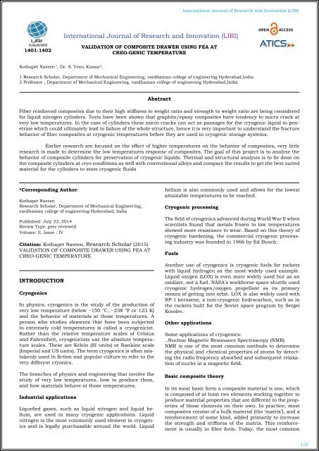
Fiber reinforced composites due to their high stiffness to weight ratio and strength to weight ratio are being considered for liquid nitrogen cylinders. Tests have been shown that graphite/epoxy composites have tendency to micro crack at very low temperatures. In the case of cylinders these micro cracks can act as passages for the cryogenic liquid to penetrate which could ultimately lead to failure of the whole structure, hence it is very important to understand the fracture behavior of fiber composites at cryogenic temperatures before they are used in cryogenic storage systems.
Fiber reinforced composites due to their high stiffness to weight ratio and strength to weight ratio are being considered
for liquid nitrogen cylinders. Tests have been shown that graphite/epoxy composites have tendency to micro crack at
very low temperatures. In the case of cylinders these micro cracks can act as passages for the cryogenic liquid to penetrate
which could ultimately lead to failure of the whole structure, hence it is very important to understand the fracture
behavior of fiber composites at cryogenic temperatures before they are used in cryogenic storage systems.

Create successful ePaper yourself
Turn your PDF publications into a flip-book with our unique Google optimized e-Paper software.
International Journal of Research and Innovation (IJRI)<br />
International Journal of Research and Innovation (IJRI)<br />
1401-1402<br />
<strong>VALID<strong>AT</strong>ION</strong> <strong>OF</strong> <strong>COMPOSITE</strong> <strong>DRAWER</strong> <strong>USING</strong> <strong>FEA</strong> <strong>AT</strong><br />
CREO-GENIC TEMPER<strong>AT</strong>URE<br />
Kothapet Naveen 1 , Dr. S. Venu Kumar 2 ,<br />
1 Research Scholar, Department of Mechanical Engineering, vardhaman college of engineering Hyderabad,India<br />
2 Professor , Department of Mechanical Engineering, vardhaman college of engineering Hyderabad,India<br />
Abstract<br />
Fiber reinforced composites due to their high stiffness to weight ratio and strength to weight ratio are being considered<br />
for liquid nitrogen cylinders. Tests have been shown that graphite/epoxy composites have tendency to micro crack at<br />
very low temperatures. In the case of cylinders these micro cracks can act as passages for the cryogenic liquid to penetrate<br />
which could ultimately lead to failure of the whole structure, hence it is very important to understand the fracture<br />
behavior of fiber composites at cryogenic temperatures before they are used in cryogenic storage systems.<br />
Earlier research are focused on the effect of higher temperatures on the behavior of composites, very little<br />
research is made to determine the low temperatures response of composites. The goal of this project is to analyse the<br />
behavior of composite cylinders for preservation of cryogenic liquids. Thermal and structural analysis is to be done on<br />
the composite cylinders at cryo conditions as well with conventional alloys and compare the results to get the best suited<br />
material for the cylinders to store cryogenic fluids<br />
*Corresponding Author:<br />
Kothapet Naveen<br />
Research Scholar, Department of Mechanical Engineering,<br />
vardhaman college of engineering Hyderabad, India<br />
Published: July 22, 2014<br />
Review Type: peer reviewed<br />
Volume: II, Issue : IV<br />
Citation: Kothapet Naveen, Research Scholar (2015)<br />
<strong>VALID<strong>AT</strong>ION</strong> <strong>OF</strong> <strong>COMPOSITE</strong> <strong>DRAWER</strong> <strong>USING</strong> <strong>FEA</strong> <strong>AT</strong><br />
CREO-GENIC TEMPER<strong>AT</strong>URE<br />
INTRODUCTION<br />
Cryogenics<br />
In physics, cryogenics is the study of the production of<br />
very low temperature (below −150 °C, −238 °F or 123 K)<br />
and the behavior of materials at those temperatures. A<br />
person who studies elements that have been subjected<br />
to extremely cold temperatures is called a cryogenicist.<br />
Rather than the relative temperature scales of Celsius<br />
and Fahrenheit, cryogenicists use the absolute temperature<br />
scales. These are Kelvin (SI units) or Rankine scale<br />
(Imperial and US units). The term cryogenics is often mistakenly<br />
used in fiction and popular culture to refer to the<br />
very different cryonics.<br />
The branches of physics and engineering that involve the<br />
study of very low temperatures, how to produce them,<br />
and how materials behave at those temperatures.<br />
Industrial applications<br />
Liquefied gases, such as liquid nitrogen and liquid helium,<br />
are used in many cryogenic applications. Liquid<br />
nitrogen is the most commonly used element in cryogenics<br />
and is legally purchasable around the world. Liquid<br />
helium is also commonly used and allows for the lowest<br />
attainable temperatures to be reached.<br />
Cryogenic processing<br />
The field of cryogenics advanced during World War II when<br />
scientists found that metals frozen to low temperatures<br />
showed more resistance to wear. Based on this theory of<br />
cryogenic hardening, the commercial cryogenic processing<br />
industry was founded in 1966 by Ed Busch.<br />
Fuels<br />
Another use of cryogenics is cryogenic fuels for rockets<br />
with liquid hydrogen as the most widely used example.<br />
Liquid oxygen (LOX) is even more widely used but as an<br />
oxidizer, not a fuel. NASA's workhorse space shuttle used<br />
cryogenic hydrogen/oxygen propellant as its primary<br />
means of getting into orbit. LOX is also widely used with<br />
RP-1 kerosene, a non-cryogenic hydrocarbon, such as in<br />
the rockets built for the Soviet space program by Sergei<br />
Korolev.<br />
Other applications<br />
Some applications of cryogenics:<br />
..Nuclear Magnetic Resonance Spectroscopy (NMR)<br />
NMR is one of the most common methods to determine<br />
the physical and chemical properties of atoms by detecting<br />
the radio frequency absorbed and subsequent relaxation<br />
of nuclei in a magnetic field.<br />
Basic composite theory<br />
In its most basic form a composite material is one, which<br />
is composed of at least two elements working together to<br />
produce material properties that are different to the properties<br />
of those elements on their own. In practice, most<br />
composites consist of a bulk material (the ‘matrix’), and a<br />
reinforcement of some kind, added primarily to increase<br />
the strength and stiffness of the matrix. This reinforcement<br />
is usually in fibre form. Today, the most common<br />
170
International Journal of Research and Innovation (IJRI)<br />
man-made composites can be divided into three main<br />
groups: Polymer Matrix Composites (PMC’s) – These are<br />
the most common and will be discussed here.<br />
Flexure<br />
Flexural loads are really a combination of tensile, compression<br />
and shear loads. When loaded as shown, the upper<br />
face is put into compression, the lower face into tension<br />
and the central portion of the laminate experiences<br />
shear.<br />
Designing with composites<br />
There are four main direct loads that any material in a<br />
structure has to withstand: tension, compression, shear<br />
and flexure.<br />
Tension<br />
Fig. shows a tensile load applied to a composite. The response<br />
of a composite to tensile loads is very dependent<br />
on the tensile stiffness and strength properties of the reinforcement<br />
fibres, since these are far higher than the<br />
resin system on its own.<br />
Stress or strain<br />
The strength of a laminate is usually thought of in terms<br />
of how much load it can withstand before it suffers complete<br />
failure. This ultimate or breaking strength is the<br />
point it which the resin exhibits catastrophic breakdown<br />
and the fibre reinforcements break.<br />
Compression<br />
Figure shows a composite under a compressive load.<br />
Here, the adhesive and stiffness properties of the resin<br />
system are crucial, as it is the role of the resin to maintain<br />
the fibres as straight columns and to prevent them from<br />
buckling.<br />
Shear<br />
Figure shows a composite experiencing a shear load. This<br />
load is trying to slide adjacent layers of fibres over each<br />
other. Under shear loads the resin plays the major role,<br />
transferring the stresses across the composite. For the<br />
composite to perform well under shear loads the resin element<br />
must not only exhibit good mechanical properties<br />
but must also have high adhesion to the reinforcement<br />
fibre. The interlaminar shear strength (ILSS) of a composite<br />
is often used to indicate this property in a multi-layer<br />
composite (‘laminate’).<br />
INTRODUCTION TO CAD<br />
Computer-aided design (CAD), also known as computer-aided<br />
design and drafting (CADD), is the use of computer<br />
technology for the process of design and designdocumentation.<br />
Computer Aided Drafting describes the<br />
process of drafting with a computer. CADD software, or<br />
environments, provides the user with input-tools for the<br />
purpose of streamlining design processes; drafting, documentation,<br />
and manufacturing processes. CADD output<br />
is often in the form of electronic files for print or machining<br />
operations. The development of CADD-based software<br />
is in direct correlation with the processes it seeks to<br />
economize; industry-based software (construction, manufacturing,<br />
etc.) typically uses vector-based (linear) environments<br />
whereas graphic-based software utilizes rasterbased<br />
(pixilated) environments.<br />
MODELING <strong>OF</strong> <strong>DRAWER</strong><br />
The above image shows sketcher<br />
171
International Journal of Research and Innovation (IJRI)<br />
The above image shows solid part of drawer<br />
Above image is showing deformation range with the help of colour<br />
bar. This value is obtaind at static condition.<br />
The above image shows final model of drawer<br />
ANALYSIS<br />
Loads:<br />
Pressure: 18.202159219200002 N/mm 2<br />
Temparcher: -160 0 C and -200 0 C.<br />
ST<strong>AT</strong>IC STRECTURAL ANALYSIS <strong>OF</strong> CYLENDER WITH<br />
STEEL<br />
Above image is showing deformation range with the help of colour<br />
bar. This value is obtaind at static condition.<br />
The above image shows the sectional view of component model<br />
was generated in ansys workbench. Sectioning is done to visualize<br />
the results of inner body.<br />
Above image is showing strain range with the help of colour bar.<br />
This value is obtaind at static condition.<br />
Above image is showing mesh model<br />
172
International Journal of Research and Innovation (IJRI)<br />
Above image is showing stress range with the help of colour bar.<br />
This value is obtaind at static condition.<br />
THERMAL ANALYSIS <strong>OF</strong> CYLENDER WITH STEEL <strong>AT</strong><br />
-160 0 C<br />
Above image is showing strain range with the help of colour bar.<br />
This value is obtaind with the variation of time(3600 sec)<br />
F<strong>AT</strong>IGUE ANALYSIS <strong>OF</strong> CYLENDER WITH STEEL<br />
Above image is showing flux range with the help of colour bar.<br />
This value is obtaind at static condition<br />
TRANSIANT STRECTURAL ANALYSIS <strong>OF</strong> CYLENDER<br />
WITH STEEL<br />
Above image is showing deformation range with the help of colour<br />
bar. This value is obtaind with the variation of time(3600 sec)<br />
173
International Journal of Research and Innovation (IJRI)<br />
ANALYSIS <strong>OF</strong> TANK WITH LAYERS METHOD<br />
Above image is showing life range with the help of colour bar.<br />
This value is obtaind with the variation of time, and static and<br />
thermal loads are used to acchive results at fully devolepped condition.<br />
The above image shows the sectional view of component model<br />
was generated in ansys APDL. Sectioning is done to visualize the<br />
results of inner body.<br />
Above image is showing damage range with the help of colour<br />
bar. This value is obtaind with the variation of time, and static<br />
and thermal loads are used to acchive results at fully devolepped<br />
condition.<br />
The above image shows layer orientation of material matrix reinforced<br />
angles.<br />
Each loading history value refers to 5000*1e005 cycles<br />
Above image is showing mesh model of the component with<br />
thickness. Meshing is used to deconstruct the complex problem<br />
in to no.of small problems which inturns simplifys the caliculation<br />
for software.<br />
174
International Journal of Research and Innovation (IJRI)<br />
Results for s2 glass with 3 layers<br />
Transient thermal with 5 layers<br />
Transient thermal analysis with 3 layers<br />
The above image shows layer orientation of material matrix reinforced<br />
angles. With 5 layers.<br />
Above image is showing gradiant range with the help of colour<br />
bar. This value is obtaind with the variation of time(3600 sec)<br />
Above image is showing gradiant range with the help of colour<br />
bar. This value is obtaind with the variation of time(3600 sec)<br />
Above image is showing flux range with the help of colour bar.<br />
This value is obtaind with the variation of time(3600 sec)<br />
Above image is showing deformation This value is obtaind with<br />
the variation of time , and static and thermal loads are used to<br />
acchive results at fully devolepped condition.<br />
Above image is showing flux range with the help of colour bar.<br />
This value is obtaind with the variation of time(3600 sec)<br />
175
International Journal of Research and Innovation (IJRI)<br />
Result tables and graphs<br />
Transient structural<br />
Couple field<br />
Fatigue<br />
Transient thermal<br />
Layers method results<br />
176
International Journal of Research and Innovation (IJRI)<br />
CONCLUSION<br />
This project work deals with the “structural and thermal<br />
analysis of axisymmetric composite cylinders (dewars) at<br />
cryo temperatures”.<br />
This project work is done on negative temparchers and<br />
effect of combinational load conditions (static& thermal),<br />
and also determines the effect on layers composite cylinders.<br />
Presents the life and damage percentage for the combinational<br />
load conditions (static& thermal) at 5000*1e005<br />
cycles each cycle with 3600 sec time.<br />
To achieve the aim of the project work following steps<br />
played the key role:<br />
•Collection of data about composites and its usage.<br />
•Literature survey given a over view of methodology and<br />
followed methods of previous study.<br />
•Static structural and thermal analysis was conducted<br />
using regular material steel and composite material s-<br />
glass epoxy at -1060c and -2000c.<br />
•Transient structural and thermal analysis was conducted<br />
using regular material steel and composite material<br />
s-glass epoxy at -1060c and -2000c.<br />
•Coupled field analysis was conducted using regular material<br />
steel and composite material s-glass epoxy to determine<br />
values at combinational load conditions (static&<br />
thermal)<br />
•Fatigue analysis conducted to determine life and damage<br />
percentage.<br />
5.Delamination of laminated fiber reinforced plastic composites<br />
under multiple cylindrical impact Debabrata Chakraborty * Department<br />
of Mechanical Engineering, Indian Institute of Technology<br />
Guwahati, Guwahati 781 039, Assam, India Received 7 June<br />
2005; accepted 24 January 2006 Available online 27 March 2006<br />
6.CRYOGENIC HE<strong>AT</strong> LOAD <strong>OF</strong> THE CORNELL ERL MAIN LINAC<br />
CRYOMODULE* E. Chojnacki#, E. Smith, R. Ehrlich, V. Veshcherevich<br />
and S. Chapman CLASSE, Cornell University, Ithaca,<br />
NY, U.S.A. Proceedings of SRF2009, Berlin, Germany<br />
7.Low-velocity impact-induced damage of continuous fiber-reinforced<br />
composite laminates. Part I. An FEM numerical model<br />
C.F. Lia,*, N. Hub, Y.J. Yina, H. Sekinec, H. Fukunagac aDepartment<br />
of Engineering Mechanics, Tsinghua University, Beijing<br />
8.Impact damage prediction in carbon fiber-reinforced laminated<br />
composite using the Matrix-reinforced mixing theory M. A.<br />
Péreza,d,_, X. Martínezb,e, S. Ollerb,d, L. Gila,d, F. Rastellinib,c,<br />
F. Floresb,f aLaboratory for the Technological Innovation of<br />
Structures and Materials (LITEM), Colon 11 TR45 08222 Terrassa,<br />
Barcelona, Spain bInternational Center for Numerical Methods<br />
in Engineering (CIMNE), Gran Capità s/n, Edifici C1, 08034<br />
9.A review on the tensile properties of natural fibre reinforced<br />
polymer composites H Ku+, H Wang, N Pattarachaiyakoop and<br />
M Trada + Corresponding author Centre of Excellence in Engineered<br />
Fibre Composites and Faculty of Engineering, University<br />
of Southern Queensland<br />
10.Significant Effect of Microwave Curing on Tensile Strength of<br />
Carbon Fiber Composites By Dr. Brian B. Balzer and Dr. Jeff<br />
McNabb Volume 24, Number 3 - July 2008 through September<br />
2008 The Official Electronic Publication of the National Association<br />
of Industrial Technology<br />
author<br />
•Layer method is done to increase cylinder quality layer<br />
reinforced method gives tremendous variation due to its<br />
lode distributing property.<br />
•Tables and graphs are presented for the results obtained<br />
in ansys.<br />
As per the obtained results reinforce composite cylinders<br />
with increased layers are the best option due to its<br />
structural and thermal behavior. Without reinforcement<br />
composite cylinder will fail due to higher stresses. Using<br />
reinforcement composite cylinder weight is reduced by 4<br />
times.<br />
Kothapet Naveen,<br />
Research Scholar,<br />
Department of Mechanical Engineering,<br />
Vardhaman college of Engineering Hyderabad,India<br />
REFERENCES<br />
1.Damage Analysis of a Type 3 Cryogenic Propellant Tank After<br />
LN2 Storage Test SANG-GUK KANG, MYUNG-GON KIM, SANG-<br />
WUK PARK AND CHUN-GON KIM* Division of Aerospace Engineering,<br />
Korea Advanced Institute of Science and Technology<br />
373-1<br />
2.Benefit of staged cooling in shrink fitted composite Cylinders<br />
Nathaniel Oren Collier University of South Florida Follow this<br />
and additional works at: http://scholarcommons.usf.edu/etd<br />
Major Professor: Autar K. Kaw, Ph.D. Glen H. Besterfield, Ph.D.<br />
Muhammad M. Rahman, Ph.D.<br />
Dr. S. Venu Kumar,<br />
Professor,<br />
Department of Mechanical Engineering,<br />
Vardhaman college of Engineering Hyderabad, India<br />
3.Analytical Design of Isolations for Cryogenic Tankers R. Miralbes,<br />
D. Valladares, L. Castejon, J. Abad, J.L. Santolaya, Member,<br />
IAENG Proceedings of the World Congress on Engineering 2013<br />
Vol III, WCE 2013, July 3 - 5, 2013, London, U.K.<br />
4.Damage and failure in low energy impact of fiber-reinforced<br />
polymeric composite laminates R.C. Batra a,G. Gopinath a, J.Q.<br />
Zheng b Contents lists available at SciVerse ScienceDirect Available<br />
online 22 August 2011<br />
177