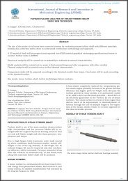
IJRI-ME-02-030 FATIGUE FAILURE ANALYSIS OF STEAM TURBINE SHAFT USING FEM TECHNIQUE

Create successful ePaper yourself
Turn your PDF publications into a flip-book with our unique Google optimized e-Paper software.
International Journal of Research and Innovation on Science, Engineering and Technology (<strong>IJRI</strong>SET)<br />
International Journal of Research and Innovation in<br />
Mechanical Engineering (<strong>IJRI</strong><strong>ME</strong>)<br />
<strong>FATIGUE</strong> <strong>FAILURE</strong> <strong>ANALYSIS</strong> <strong>OF</strong> <strong>STEAM</strong> <strong>TURBINE</strong> <strong>SHAFT</strong><br />
<strong>USING</strong> <strong>FEM</strong> <strong>TECHNIQUE</strong><br />
D.Jojappa 1 , K.Naresh babu 2 , K.krishnaveni 3 .<br />
1 Research Scholar, Department of Mechanical Engineering, Chebrolu engineering college, Guntur, AP, India.<br />
2 Assistant professor, Department of Mechanical Engineering, Chebrolu engineering college, Guntur, AP, India.<br />
3 Associate professor, Department of Mechanical Engineering, Chebrolu engineering college, Guntur, AP, India.<br />
Abstract<br />
The aim of the project is to locate best constrain location by evaluating steam turbine shaft with different materials.<br />
Initially data collection will be done to understand rectification methodology and approach.<br />
A 3D model of shaft will be prepared and exported into IGES (inertial graphical exchanging specifications) format to<br />
conduct further work in ANSYS.<br />
Structural analysis will be carried out on assembly to evaluate structural characteristics.<br />
Model analysis will be carried out on same to find natural frequency’s (for comparison with other results)<br />
Thermal analysis will be carried out on to find thermal characteristic.<br />
Comparison tables will be prepared according to the obtained results from Ansys; Conclusion will be made according<br />
to the obtained results.<br />
Key words: steam turbine, shaft, hollow shaft,fatigue failure analysis.<br />
*Corresponding Author:<br />
D.Jojappa,<br />
Research Scholar, Department of Mechanical Engineering,<br />
Chebrolu engineering collage, Guntur, AP, India.<br />
Email: darajojappa@gmail.com<br />
Year of publication: 2016<br />
Review Type: peer reviewed<br />
Volume: III, Issue : I<br />
Citation: D.Jojappa, Research Scholar, "Fatigue Failure Analysis<br />
of Steam Turbine Shaft Using Fem Technique" International<br />
Journal of Research and Innovation on Science, Engineering<br />
and Technology (<strong>IJRI</strong>SET) (2016) 194-198<br />
It has almost completely replaced the reciprocating piston<br />
steam engine primarily because of its greater thermal<br />
efficiency and higher power-to-weight ratio. Because the<br />
turbine generates rotary motion, it is particularly suited<br />
to be used to drive an electrical generator – about 80% of<br />
all electricity generation in the world is by use of steam<br />
turbines. The steam turbine is a form of heat engine that<br />
derives much of its improvement in thermodynamic efficiency<br />
through the use of multiple stages in the expansion<br />
of the steam, which results in a closer approach to<br />
the ideal reversible process.<br />
MODELS <strong>OF</strong> <strong>STEAM</strong> <strong>TURBINE</strong> <strong>SHAFT</strong><br />
INTRODUCTION <strong>OF</strong> <strong>STEAM</strong> <strong>TURBINE</strong> <strong>SHAFT</strong><br />
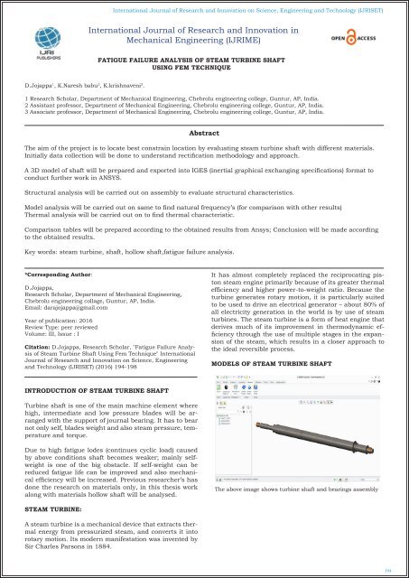
Turbine shaft is one of the main machine element where<br />
high, intermediate and low pressure blades will be arranged<br />
with the support of journal bearing. It has to bear<br />
not only self, blades weight and also steam pressure, temperature<br />
and torque.<br />
Due to high fatigue lodes (continues cyclic load) caused<br />
by above conditions shaft becomes weaker; mainly selfweight<br />
is one of the big obstacle. If self-weight can be<br />
reduced fatigue life can be improved and also mechanical<br />
efficiency will be increased. Previous researcher’s has<br />
done the research on materials only, in this thesis work<br />
along with materials hollow shaft will be analysed.<br />
The above image shows turbine shaft and bearings assembly<br />
<strong>STEAM</strong> <strong>TURBINE</strong>:<br />
A steam turbine is a mechanical device that extracts thermal<br />
energy from pressurized steam, and converts it into<br />
rotary motion. Its modern manifestation was invented by<br />
Sir Charles Parsons in 1884.<br />
194
International Journal of Research and Innovation on Science, Engineering and Technology (<strong>IJRI</strong>SET)<br />
The above image shows hallow shaft and bearings assembly<br />
MATERIALS AND BOUNDARY CONDITIONS:<br />
Weight= volume X density<br />
Equivalent stress value, it is also called as vonmisses stress<br />
which provides the average value of directional and principle<br />
stress using vonmisses theory of failure.<br />
THERMAL <strong>ANALYSIS</strong> FOR SOLID MODEL-MATERIAL1<br />
Low pressure blade set= 4695903 X 0.00000785 Kg/mm 3<br />
= 36.86<br />
Intermediate pressure blade set= 2390470 X 0.00000785 Kg/<br />
mm 3 = 18.76<br />
High pressure blade set= 2163510 X 0.00000785 Kg/mm 3<br />
= 16.98<br />
Weight X newton’s = load<br />
Low pressure blade set = 36.86 X 9.81=361.228<br />
Intermediate pressure blade set = 18.76 X 9.81=184.142<br />
High pressure blade set = 16.98 X 9.81=166.404<br />
Load /area = pressure<br />
Shaft Area of each blade set = 268535mm<br />
Low pressure blade set = 0.0013<br />
Intermediate pressure blade set = 0.000685<br />
High pressure blade set = 0.000619<br />
Total heat flux<br />
<strong>FATIGUE</strong> <strong>ANALYSIS</strong> FOR SOLID MODEL-MATERIAL 1<br />
Material 1<br />
AISI 4130 Steel (super alloy steel) Material 1<br />
Material 2<br />
Haynes Hastelloy C-276 alloy<br />
STRUCTURAL <strong>ANALYSIS</strong> FOR SOLID MODEL-MATE-<br />
RIAL 1<br />
Safety factor range on object<br />
STRUCTURAL <strong>ANALYSIS</strong> FOR HALLOW MODEL-MA-<br />
TERIAL 1<br />
Total deformation<br />
Equivalent stress<br />
195
International Journal of Research and Innovation on Science, Engineering and Technology (<strong>IJRI</strong>SET)<br />
THERMAL <strong>ANALYSIS</strong> FOR HALLOW MODEL MATE-<br />
RIAL 1<br />
Total heat flux<br />
<strong>FATIGUE</strong> <strong>ANALYSIS</strong> FOR HALLOW MODEL- MATERI-<br />
AL 1<br />
The above image shows hallow shaft, bearings and center support<br />
bearing<br />
STRUCTURAL <strong>ANALYSIS</strong> FOR HALLOW MODEL WITH<br />
CENTER BEARING-MATERIAL 2<br />
Maximum life<br />
STRUCTURAL <strong>ANALYSIS</strong> FOR HALLOW MODEL-MA-<br />
TERIAL 2<br />
Equivalent stress value, it is also called as vonmisses stress<br />
which provides the average value of directional and principle<br />
stress using vonmisses theory of failure.<br />
<strong>FATIGUE</strong> <strong>ANALYSIS</strong> FOR HALLOW MODEL WITH<br />
CENTER BEARING-MATERIAL 2<br />
Total deformation<br />
RESULT TABLES<br />
Safety factor range on object.<br />
Equivalent stress<br />
Materials AISI 4130<br />
Steel<br />
Total deformation<br />
STRUCTURAL <strong>ANALYSIS</strong><br />
Solid shaft<br />
C-276<br />
alloy<br />
AISI 4130<br />
Steel<br />
Hallow shaft<br />
C-276<br />
alloy<br />
0.<strong>02</strong>1188 0.<strong>02</strong>233 0.<strong>02</strong>7235 0.<strong>02</strong>6332<br />
Stress 44.67 42.056 73.184 69.301<br />
Strain 0.00<strong>02</strong>21 0.00<strong>02</strong>13 0.000437 0.000426<br />
196
International Journal of Research and Innovation on Science, Engineering and Technology (<strong>IJRI</strong>SET)<br />
Materials AISI 4130<br />
Steel<br />
Temperature<br />
THERMAL <strong>ANALYSIS</strong><br />
Solid shaft<br />
C-276<br />
alloy<br />
AISI 4130<br />
Steel<br />
Hallow shaft<br />
C-276<br />
alloy<br />
591.63 579.95 588.53 577.73<br />
Heat flux 0.66966 0.42049 0.60857 0.38725<br />
Thermal<br />
error<br />
Materials AISI 4130<br />
Steel<br />
Total deformation<br />
HZ 1<br />
Total deformation<br />
HZ 2<br />
Total deformation<br />
HZ 3<br />
Total deformation<br />
HZ 4<br />
Total deformation<br />
HZ 5<br />
Materials AISI 4130<br />
Steel<br />
7.4585e6 1.7605e6 4.7633e6 9.8352e5<br />
MODEL <strong>ANALYSIS</strong><br />
Solid shaft<br />
C-276<br />
alloy<br />
AISI 4130<br />
Steel<br />
Hallow shaft<br />
C-276<br />
alloy<br />
144.92 143.39 168.41 166.42<br />
145.18 143.65 177.22 175.15<br />
418.62 413.79 372.42 368.31<br />
419.11 414.27 382.68 378.51<br />
709.51 695.61 475.99 470.09<br />
<strong>FATIGUE</strong> <strong>ANALYSIS</strong><br />
Solid shaft<br />
C-276<br />
alloy<br />
AISI 4130<br />
Steel<br />
Hallow shaft<br />
C-276<br />
alloy<br />
LIFE 5e11 5e11 5e11 5e11<br />
Damage 1.034 0.86538 3.7329 3.2395<br />
HALLOW <strong>SHAFT</strong> WITH CENTER SUPPORT BEARING<br />
TABLE<br />
Materials<br />
STRUCTURAL <strong>ANALYSIS</strong><br />
C-276 alloy<br />
Total deformation 0.22403<br />
Stress 65.783<br />
Strain 0.00041147<br />
Materials<br />
THERMAL <strong>ANALYSIS</strong><br />
C-276 alloy<br />
Temperature 577.73<br />
Heat flux 0.38723<br />
Thermal error 9.8352e5<br />
Materials<br />
MODEL <strong>ANALYSIS</strong><br />
C-276 alloy<br />
Total deformation HZ 1 372.95<br />
Total deformation HZ 2 383.67<br />
Total deformation HZ 3 953.67<br />
Total deformation HZ 4 975.5<br />
Total deformation HZ 5 1190.4<br />
Materials<br />
LIFE<br />
<strong>FATIGUE</strong> <strong>ANALYSIS</strong><br />
C-276 alloy<br />
5e11<br />
Damage 2.8291<br />
CONCLUSION<br />
This thesis work deals with “<strong>FATIGUE</strong> <strong>FAILURE</strong> ANAL-<br />
YSIS <strong>OF</strong> <strong>STEAM</strong> <strong>TURBINE</strong> <strong>SHAFT</strong> <strong>USING</strong> <strong>FEM</strong> TECH-<br />
NIQUE” to compare solid and hollow shafts; to suggest<br />
best material and suitable location for the center bearing.<br />
Structural, model, thermal and fatigue analysis is done<br />
on solid and hollow shafts along with bearings by varying<br />
materials; as per the analysis results hollow shaft is<br />
having little bit high stress and deformation but these are<br />
within the limit only while considering factor of safety.<br />
Bearing was installed near high pressure blades for additional<br />
support to use hollow shaft to reduce stress concentration;<br />
then above analysis was conducted to evaluate<br />
results.<br />
As per the analysis work results hollow shaft with center<br />
bearing and C-276 material will be the better option; using<br />
these conditionsshaft weight can be reduced up to<br />
51kgs [^16%] which interns increases the mechanical efficiency.<br />
REFERENCE<br />
1.THERMAL STRESS <strong>ANALYSIS</strong> IN <strong>STEAM</strong> <strong>TURBINE</strong> RO-<br />
TOR - A REVIEW by Ms. Mohini R. Kolhe1, Prof. A. D.<br />
Pachchhao2, Prof. H.G.Nagpure3.<br />
2.Calculation of Thermal Stress and Fatigue Life of 1000<br />
MW Steam Turbine Rotor by ShuangBian, Wenyao Li.<br />
3.DESIGN AND <strong>ANALYSIS</strong> <strong>OF</strong> <strong>STEAM</strong> <strong>TURBINE</strong> ROTOR<br />
byM. Chandra Sekhar Reddy.<br />
4.Residual Life Assessment of 60 MW Steam Turbine Rotor<br />
by K. Venkatesh*, P. VeeraRaju**, T. Jayananda Kumar**<br />
5.TRANSIENT THERMAL <strong>ANALYSIS</strong> <strong>OF</strong> A <strong>STEAM</strong> TUR-<br />
BINE ROTOR by Shilpa P. Bhorkar, Dr. A.V. Vanalkar.<br />
6.ZvonimirGuzović, BranimirMatijašević, TihomirMihalić<br />
“Characteristics Of Non- Stationary Thermal Stresses In<br />
The Low-Pressure Part Of The Rotor”15th International<br />
Research/Expert Conference TMT-2011,Prague,Czech<br />
Republic 12-18 September 2011.<br />
7.Chunlin Zhang, Niansu Hu, Jianmei Wang,<br />
Qiping,chen,FengHe,Xiaoli “ Thermal Stress Analysis<br />
for Rotor of 600MW Steam Turbine”978-1-4244-4813-<br />
5/10/&25.00c/2010/IEEE.<br />
8.G SukhvinderKaurBhatti, ShyamalaKumari, M L Neelapu,<br />
C Kedarinath, Dr. I N Niranjan Kumar” Transient<br />
State Stress Analysis On An Axial Flow Gas Turbine<br />
Blades And Disk Using Finite Element Procedure”. in Int.<br />
Conf. on HEAT TRANSFER, THERMAL ENGINEERING<br />
and ENVIRON<strong>ME</strong>NT, Elounda, Greece, August 21-23,<br />
2006 (pp323-330).<br />
9.Deepak Dhar, A. M. Sharan.” Transient Stress Analysis<br />
and Fatigue Life Estimation of Turbine Blades” Journal of<br />
Vibration and Acoustics OCTOBER 2004, Vol. 126 Õ 495.<br />
197
International Journal of Research and Innovation on Science, Engineering and Technology (<strong>IJRI</strong>SET)<br />
10.Yong Li, Haoran Sun, YuhuoNie “Thermal Stress Analysis<br />
of 600MW Steam Turbine Rotor in Different Governing<br />
Modes” 978-1-422-4813-5 28-31-March2010 IEEE.<br />
11.Sudheendra,V.S,SRamamurthKMurugesan”Transie<br />
nt,Thermal Analysis Of A Turbine Rotor”nal-ir.nal.res.<br />
in/8928 [7]Stuart R Holdsworth , EdoardoMazza&Arnd<br />
Jung” creep-fatigue damage developmentduring servicecycle<br />
thermo-mechanical fatigue test of 1CrMoV rotor<br />
steel”.<br />
Author<br />
D.Jojappa,<br />
Research Scholar, Department of Mechanical Engineering,<br />
Chebrolu engineering college, Guntur, AP, India.<br />
K.Naresh babu,<br />
Assistant professor, Department of Mechanical Engineering,<br />
Chebrolu engineering college, Guntur, AP, India.<br />
K.krishnaveni,<br />
Associate professor, Department of Mechanical Engineering,<br />
Chebrolu engineering college, Guntur, AP, India.<br />
198