Principles and Practical Aspects of Preparative Liquid Chromatography

Create successful ePaper yourself
Turn your PDF publications into a flip-book with our unique Google optimized e-Paper software.
Gradient pump<br />
<strong>Preparative</strong> column<br />
Channel A<br />
Detector<br />
Channel B<br />
2<br />
3<br />
1<br />
4<br />
6<br />
5<br />
Injection<br />
(valve in pos. 1)<br />
Fraction collector<br />
2<br />
3<br />
4<br />
5<br />
1<br />
6<br />
12<br />
7<br />
11<br />
10<br />
9<br />
8<br />
Sampling<br />
valve<br />
Waste<br />
Injection pump<br />
Sample container<br />
Gradient pump<br />
<strong>Preparative</strong> column<br />
Channel A<br />
Detector<br />
Channel B<br />
2<br />
3<br />
1<br />
4<br />
6<br />
5<br />
Elution<br />
(valve in pos. 2)<br />
Fraction collector<br />
2<br />
3<br />
4<br />
5<br />
1<br />
6<br />
12<br />
7<br />
11<br />
10<br />
9<br />
8<br />
Sampling<br />
valve<br />
Waste<br />
Injection pump<br />
Sample container<br />
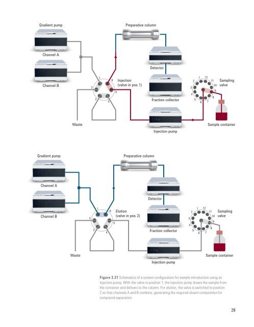
Figure 3.21 Schematics <strong>of</strong> a system configuration for sample introduction using an<br />
injection pump. With the valve in position 1, the injection pump draws the sample from<br />
the container <strong>and</strong> delivers to the column. For elution, the valve is switched to position<br />
2 so that channels A <strong>and</strong> B combine, generating the required eluent composition for<br />
compound separation.<br />
26